

WVOS541
W
a
WV
(WVOM541AP+WVCMS130AP)
WVOM
Digital
Digital Wireless
bserv
Observation System
WVOM541AP
WVCMS130AP
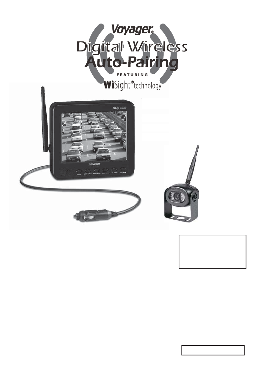
KEY FEATURES:
● Easy installation, fi ts most applications
● 5.6" monitor comes with suction cup mount and
12 Volt DC plug for easy portability
● Camera connects to rear clearance lights
● WiSight
● No interference
● Signal transmits through and around objects up to 60+ feet away
● Sharp,clear,uninterrupted picture
● Extend to 4 wireless and 1 wired cameras available
● Camera source with trigger selection available
(Optional Harness with Trigger function sold separately )
● Image mirror function available
● Image fl ip function available
Package includes a 5.6" LCD color monitor, one 12 Volt DC accessory plug,
a suction cup monitor mount, one rear color camera, stainless steel hardware,
and non-corrosive camera mounting bracket.
®
technology- No cable or wiring necessary
YOU WILL NEED:
● Voltage Meter
● Water Proof Sealant
● Drill with 1/8" drill bit
● Phillips head screwdriver
English
Patent # (9,054,743)
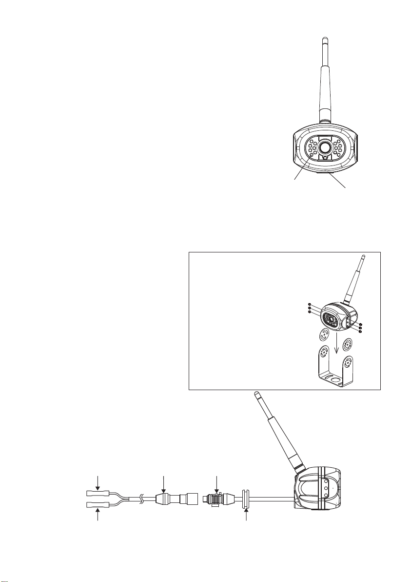
INSTALLING THE CAMERA
1. Choose a location close to the rear clearance lights so you
can easily splice the power and ground connections.
2. Using a voltage meter, measure the clearance light wiring
to deter mine positive/negative polarity.
3. Connect the red wire from the camera to the positive
wire in the rear clearance lights.
4. Connect the black wire from the camera to the
negative wire in the rear clearance lights.
5. Pre-drill the screw holes for the mounting
bracket with an 1/8" drill bit.
6. Apply a weather proof sealant to the pre-drilled holes.
7. Align the bracket to the holes.
8. Install the bracket with the supplied Tapping P/H screws with washers.
9. Apply additional sealant to the screw heads and bracket to ensure a
weather proof seal.
10. Align the camera in the bracket
Installation
(Figure 1).
11. Install with the supplied Hex
Socket Head stainless screws
and larger washers in the
corresponding holes(Figure 2).
Screw For Use
● Hex Socket Head M4xM6L
stainless screw
● Flat Washers 4.5x9.5x1mm
● Stainless Allen wrench
12. Camera should be adjusted for
optimum view before these
screws are fully tightened.
LED Assisted
Illumination
FIGURE 2
FIGURE 1
Microphone
Standard Cable
12V DC
Red
Black
Ground/Shield Grommet To Seal Through
Connector
Waterproof Camera
Connector
Vehicle Exterior
EN-01

INSTALLING THE MONITOR
1. Plug power cable into the back of the monitor.
2. Attach the suction cup bracket to the rear of the monitor with the supplied screw.
3. Locate fl at section of glass on your windshield (that does not block your vision)
and apply suction cup. Snap the lever into the locked position (Figure 5).
4. Connect the power cord to a 12 Volt DC outlet.
5. Align the antenna to its upright position, parallel to the monitor.
RED – +12V
BLACK – GND
BLUE – Trigger 1
ORANGE – Trigger 2
GREEN – Trigger 3
YELLOW –Trigger4
BROWN – Trigger 5
OPERATION
1. Press the power button on the monitor and turn on your vehicle's parking lights.
2. In the top right corner of the monitor, you will see the signal strength meter.
3. Adjust the suction cup bracket to provide the best viewing angle.
4. Press and hold the "POWER" button for 5 seconds and release to
setup monitor " Mirror ON" or "Mirror OFF"
PAIRING PROCESS
This system has Auto-Pairing function. If your monitor is not receiving a signal from
the camera; the two may not be paired correctly.
1. Monitor must be connected to 12 Volt DC power supply.
2. Press the SELECT/PAIR button on the front of the monitor expected mode & select the
appropriate AV source (AV1-AV4)
3. Press and hold the "SELECT/PAIR" button on the front of the monitor for 5 seconds and
release. (Monitor will display "PAIRING START")
4. Apply 12 Volt DC power to the camera.(Camera 1 - Camera 4 corresponding to
Monitor's AV1 - AV4)
If done correctly, monitor will display "SAVE DATA". If pairing is not successful, the
monitor will display "PAIRING FAIL". if you receive this message, repeat steps 3-4.
EN-02

CAMERA-MONITOR WARNINGS!
1. Camera/Monitor system aids in the use of, but does not replace vehicle side/rear-view mirrors.
2. Objects in Camera/Monitor view are closer than they appear.
When backing up, processed cautiously and be prepared to stop.
IMPORTANT NOTE:
To comply with the FCC RF exposure compliance requirements, the antenna(s) used for this transmitter
must be installed to provide a separation distance of at least 20 cm from all persons and must not be colocated or operating in conjunction with any other antenna or transmitter. No change to the antenna or
the device is permitted.
Any change to the antenna or the device could result in the device exceeding the RF exposure
requirements and void user's authority to operate the device.
NOTICE 1 :
Any changes or modifi cations not expressly approved by the grantee of this device could void the user's
authority to operate the equipment.
NOTICE 2:
Our WiSight wireless technology operates at nearly the same performance level as a wired system.
However, slight delays and signal reductions are possible due to application or environmental factors.
It is recommended to maintain at least three feet in between any RF transmitting/receiving devices
including the WiSight components. This can include, but not limited to, in-vehicle Wi-Fi systems,
personal Wi-Fi hotspots, Bluetooth devices or additional wireless monitors & cameras.
If you have a Voyager WiSight Digital Wireless Observation System along with any other device that
transmits or receives and you are experiencing diffi culty in operating the system, the device(s) may be
too close to either the WiSight Monitor or Camera.
Change the placement to at least three feet between devices and re-test for proper operation.
FEDERAL COMMUNICATIONS COMMISSION INTERFERENCE STATEMENT
This equipment has been tested and found to comply with the limits for a Class B digital device, pursuant
to part 15 of the FCC Rules. These limits are designed to provide reasonable protection against harmful
interference in a residential installation. This equipment generates, uses and can radiate radio frequency
energy and, if not installed and used in accordance with the instructions, may cause harmful interference
to radio communications. However, there is no guarantee that interference will not occur in a particular
installation. If this equipment does cause harmful interference to radio or television reception, which
can be determined by turning the equipment off and on, the user is encouraged to try to correct the
interference by one or more of the following measures:
- Reorient or relocate the receiving antenna.
- Increase the separation between the equipment and receiver.
- Connect the equipment into an outlet on a circuit different from that to which the receiver is connected.
- Consult the dealer or an experienced radio/ TV technician for help.
TROUBLE SHOOTING
Monitor will not turn on.
Monitor display "No Signal".
Intermittent reception.
Features and specifi cations subject to change with out noticve
For further technical support call: 1-877-305-0445
- Check power cord connection at monitor
and 12VDC socket.
- Check fuse in cigarette socket adapter.
- Check 12VDC power at camera.
- Make sure antenna is tight and pointed
correctly.
- Make sure monitor is set to AV1.
- Try manually pairing the system.
see pairing Process for instructions.
- Make sure antenna is tight and installed
vertically.
EN-03
 Loading...