

Page 1
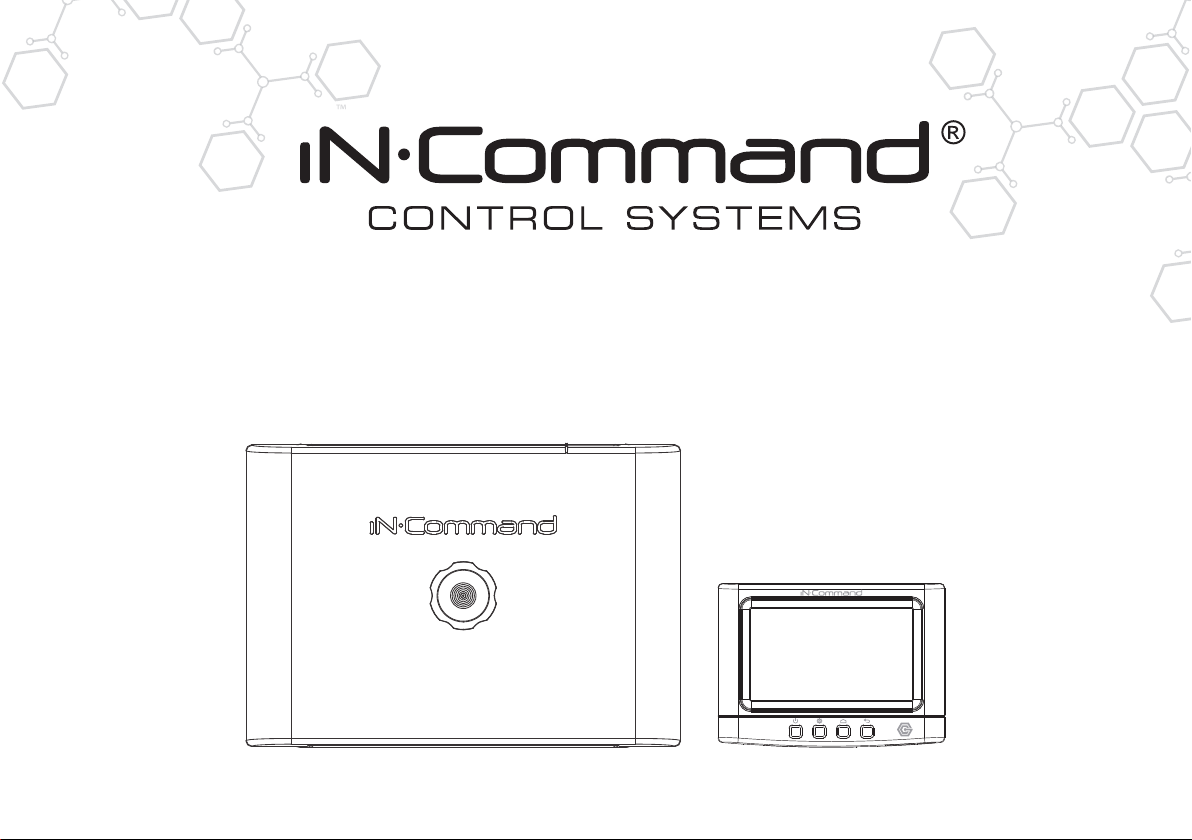
NCSP35
RV CONTROL AND MONITORING SYSTEM
Installation and Operation Manual
Patent # US 9,679,735
Page 2

Page 3
NCSP35
Important Safety Information
Read the iN-Command Manual, and these warnings and instructions carefully before using this product. Failure to follow the use
instructions in this owner’s manual, or improper use of the Mobile Application, Display Commander and/or Body Control Module, could
result in personal injury, including death.
Do not operate while vehicle is being driven.
The Mobile Application, Display Commander and/or Body Control Module should not be used while the vehicle is being driven. Use of
the Mobile Application, Display Commander and/or Body Control Module while the vehicle is being driven is dangerous and may cause
personal injury or property damage.
For adult use only.
The Mobile Application, Display Commander and Body Control Module are intended for adult use only, and are not to be used by persons
under the age of 18. Use by children may cause personal injury or property damage.
Operate only when you have a clear line of sight.
Do not operate any moving parts (including, but not limited to, awnings, jacks and slides), unless you have a clear line of sight to the
moving part. The Mobile Application, Display Commander or Body Control Module may be used only if you are giving instructions to,
and receiving instructions from, another person at least age 18 or older who can clearly see the moving part. Failure to follow these
instructions may result in serious personal injury or property damage.
Do not operate under the influence of alcohol or drugs.
Do not operate the Mobile Application, Display Commander or Body Control Module while under the inuence of alcohol or drugs. Doing
so may result in personal injury or property damage.
Avoid moisture.
To reduce the risk of re or electric shock, do not expose this equipment to rain or moisture.
Use recommended accessories.
To reduce the risk of re or electric shock and annoying interference, use only the recommended accessories.
Page 4
NCSP35
• TABLE OF CONTENTS
INTRODUCTION .....................................................................4
Thank You! ............................................................................. 4
Features .................................................................................4
Precautions ............................................................................4
Packing List ............................................................................4
INSTALLATION ........................................................................5
Tools and Supplies ................................................................. 5
Disconnecting the battery .......................................................5
Selecting the Mounting Location ............................................ 5
Mounting the Display Commander (DC) ................................5
WIRING ...................................................................................6
BCM AND DC WIRING DIAGRAM ..........................................7
SETUP MENU LIST .................................................................8
TRAVEL LOCKOUT (Safety) ...................................................9
OVERRIDE SWITCHES* .......................................................10
DISPLAY COMMANDER BUTTONS ..................................... 10
SPECIFICATIONS .................................................................11
FCC NOTES .......................................................................... 11
PASSCODE PROTECTION ..................................................12
SETTINGS .............................................................................12
Text Editing* ......................................................................... 12
Scroll List Editing ..................................................................14
Slides ...................................................................................15
Awning .................................................................................15
Alarm Inputs .........................................................................15
Passcode .............................................................................16
Set Passcode Timer ..........................................................17
Change Passcode .............................................................17
Clear Passcode .................................................................17
MOBILE DEVICES: ...............................................................18
Pairing Mobile Device to DC ................................................19
CHECKING ACTIVE BLUETOOTH SESSION ....................................23
HVAC ....................................................................................................24
Vent Fans ............................................................................................24
Fan Only Mode .................................................................................... 24
AC Cooling .......................................................................................... 24
Heating ................................................................................................ 25
Auto ..................................................................................................... 25
HVAC Schedule ..................................................................................26
SOFTWARE UPDATE* ......................................................................... 27
RESET: FLOOR PLAN ......................................................................... 30
TOUCH SCREEN CALIBRATION ........................................................ 31
SYSTEM CALIBRATION* .....................................................................32
TROUBLESHOOTING .......................................................................... 34
3
Page 5
NCSP35
• INTRODUCTION
• Thank You!
Thank you for choosing iN-Command. We hope you will nd the
instruc tions in this owner’s manual clear and easy to follow. If you take
a few minutes to look through it, you’ll learn how to use all the features
of your new NCSP35 for maximum enjoyment.
• Features
Features of iN-Command system include:
• Simultaneous control by up to three Android Devices and one iOS
Device
• Control two zones of Interior Lighting
• Monitor all water tank levels
• Control and monitor the Water Heater (switches between LP or AC)
• Control and monitor the Water Pump
• Control Awning
• Control Electric Slides
• Control Jacks (non-automatic function)
• Monitor Battery Voltage with Low Voltage Alert
• HVAC
• Use Recommended Accessories.
TO REDUCE THE RISK OF FIRE OR ELECTRIC SHOCK AND
ANNOYING INTERFERENCE, USE ONLY THE RECOMMENDED
ACCESSORIES.
• Packing List
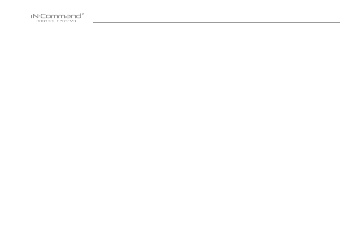
(1) Cover, (1) Thumb Screws (1) Body Control Module (BCM)
• Precautions
• Use the Proper Power Supply.
This product is designed to operate with a 12 volt DC, negative ground
battery system (the standard system in a North American vehicle).
• Use Authorized Service Centers.
Do not attempt to disassemble or adjust this precision product; contact
a professional for assistance.
• Avoid Moisture.
To reduce the risk of re or electric shock, do not expose this equipment
to rain or moisture.
• Avoid Cleaning Products.
The front of this unit should only be cleaned with a slightly damp cloth.
Do not use cleaning products.
(1) Display Commander (DC)
4
Page 6
NCSP35
• INSTALLATION
It’s a good idea to read all of the instructions before beginning the
installation. We recommend having your NCSP35 installed
by a reputable RV dealership
• Tools and Supplies
You will need these tools and supplies to install your NCSP35 :
• Phillips screwdriver
• #2 square drive bit
• Wire cutters and strippers
• Electrical tape
• Volt meter/test light
• Crimping tool
• Fork Crimp connectors
• Minimum of 24 gauge wire required to connect DC to BCM
• 10 gauge wire for power and slide connections
• 14 and 18 gauge wire for all other connections
• Four #8 PH (0.164” x 0.75”) screws for the DC
• Six #8 PH (0.164” x 1.0”) screws for the BCM
• Disconnecting the battery
To prevent a short circuit, be sure to turn off 12V power and remove
the negative (-) battery cable prior to installation.
• Selecting the Mounting Location
Select a mounting location, taking care to avoid the following:
• Places exposed to heat-radiating appliances such as electric heaters
• Adjacent to other equipment that radiates heat
• Under thermostats
• Poorly-ventilated or dusty places
• Moist or humid locations
• Mounting the Display Commander (DC)
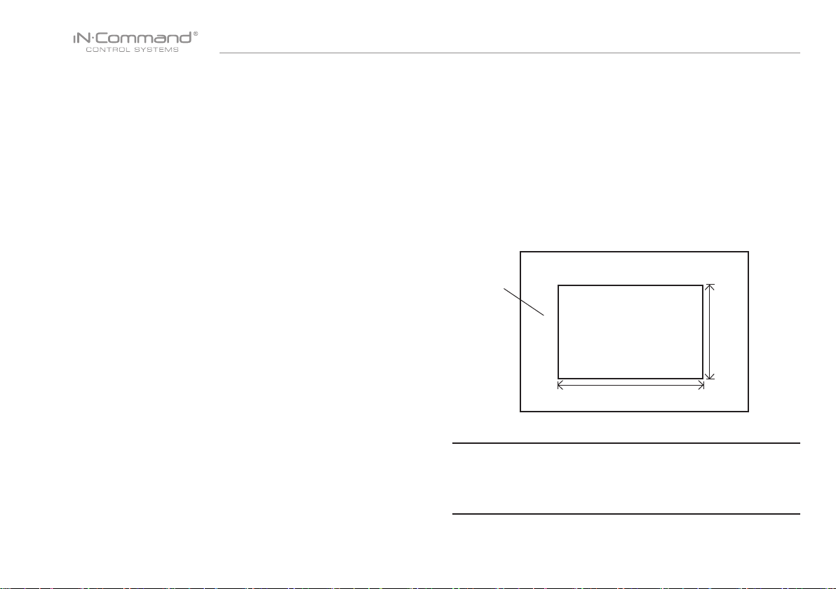
• Use the mounting hole diagram to measure and cut a mounting hole,
allowing space below for future programming and behind for
ventilation
• Route power and transmit wires through the hole and connect
• Check and ensure correct operation
• Mount the unit using four #8 PH (0.164” x 0.75”) screws
• Attach Trim ring
CUTOUT FOR DISPLAY COMMANDER (DC)
RECOMMENDED CUTOUT
WALL FOR
REFERENCE
CUTOUT
4.3"
NOTE: Before cutting the mounting hole, make sure the area
behind the mounting location is clear of wires, fuel and vacuum
or water lines; ensure there is at least a 2.75”clearance below
the Display Commander to allow for programming by USB stick.
3.0"
5
Page 7
NCSP35
• WIRING
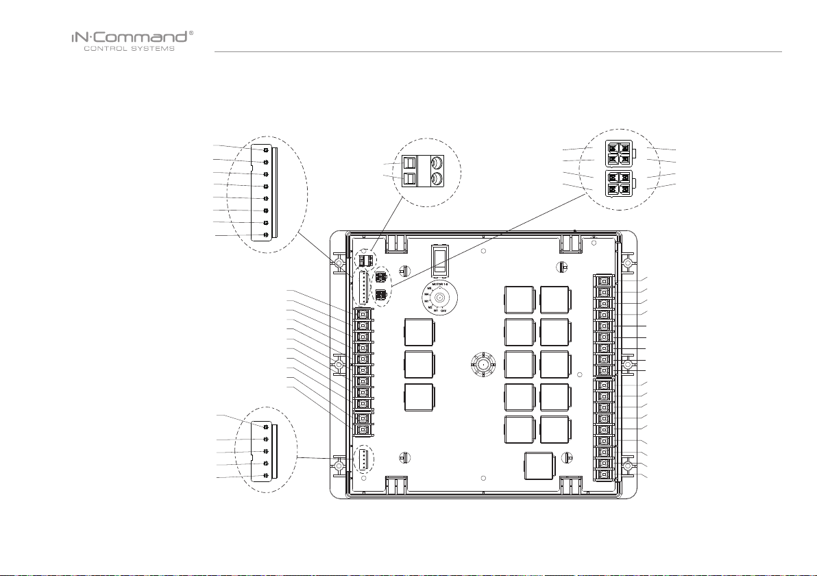
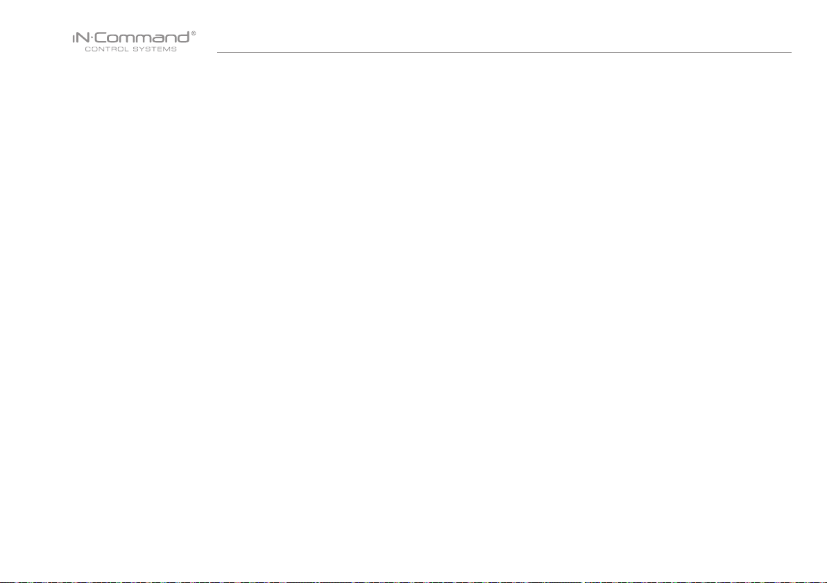
The Wiring Diagram Depicts All The Wiring Connections Required For Proper Operation Of The Unit.
Body Control Module (BCM) Connections
FRESH 1 TANK IN (BROWN) -1
FRESH 2 TANK IN (RED) - 2
BLACK 1 TANK IN (ORANGE) - 3
BLACK 2 TANK IN (YELLOW) - 4
GREY 1 TANK IN (GREEN) - 5
GREY 2 TANK IN (BLUE) - 6
GREY 3 TANK IN (PURPLE) - 7
TANK LEVEL COMMON 7VDC (GRAY) - 8
LIGHT GROUP 1 SWITCH INPUT 12V - 9
LIGHT GROUP1 GND - 11
LIGHT GROUP1 12V 15A OUT - 12
LIGHT GROUP 2 SWITCH INPUT 12V - 13
TRAVEL LOCK IN 12V (BROWN) - 20
WATER HEATER GND (RED) - 21
WATER HEATER GAS +12V 1A OUT (ORANGE) - 22
WATER HEATER ELECTRIC +12V 1A OUT (YELLOW) - 23
+12V WATER HEATER FAULT IN (GREEN) - 24
LIGHT GROUP2 GND - 14
LIGHT GROUP2 12V 15A OUT - 15
AWNING SWITCH INPUT 12V - 16
AWNING LIGHT 12V 5A OUT - 18
DETAIL A
LIGHT 12V 15A IN - 10
GND - 17
AWNING LIGHT GND -19
DETAIL B
1
2
3
4
5
6
7
8
20
21
22
23
24
GND - 52
+12VDC OUT - 51
10
11
12
13
14
15
16
17
18
19
DETAIL C
50
49
46
45
50- NC
49- NC
46- NC
45- NC
42 - +12VDC IN POWER HOUSE
41 - +12VDC IN POWER CHASSIS
40 - 12V IN 30 AMP SLIDE & JACK POWER
39 - GROUND IN
38 - 12V OUT 30 AMP (SLIDE#1)
37 - GND OUT (SLIDE#1)
36 - 12V OUT 30 AMP (SLIDE#2)
35 - GND OUT (SLIDE#2)
34 - 12V OUT 30 AMP (SLIDE#3)
33 - GND OUT (SLIDE#3)
32 - 12V OUT 30 AMP (SLIDE#4)
31 - GND OUT (SLIDE#4)
30 - 12V OUT 30 AMP (SLIDE#5)
29 - GND OUT (SLIDE#5)
28 - WATER PUMP +12V IN 10A
27 - WATER PUMP GND
26 - WATER PUMP +12V OUT 10A
25 - GND
CAN LOW - 48
52
51
DETAIL D
9
CAN HIGH - 47
CAN LOW - 44
CAN HIGH - 43
48
47
44
43
42
41
40
39
38
37
36
35
34
33
32
31
30
29
28
27
26
25
6
Page 8
NCSP35
• BCM AND DC WIRING DIAGRAM
7
Page 9
NCSP35
• SETUP MENU LIST
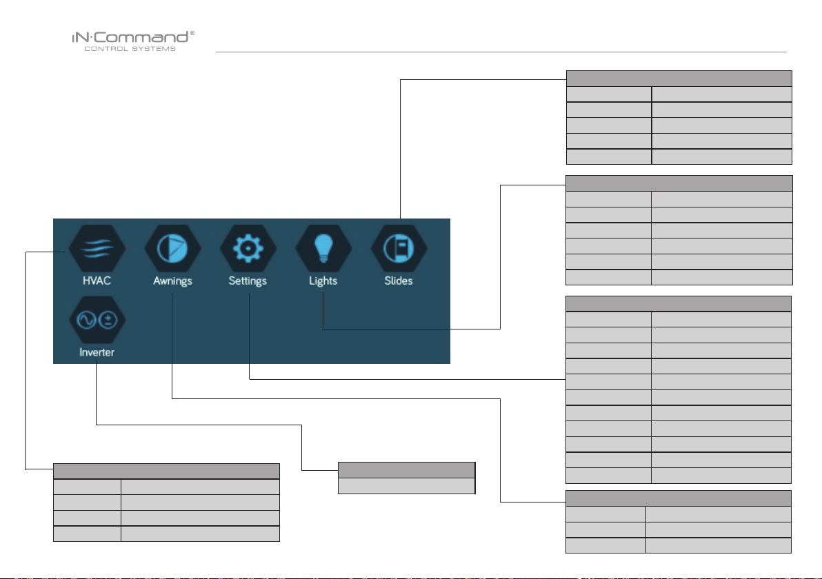
Tanks, light groups, and motor functions can be added or removed.
Motor functions may include slides, awnings, jacks, or any motor
that may be controlled with a momentary switch.
Refer to the Wiring Diagram and Terminal List when installing new
equipment. The BCM may not include relays for non-OEM
functions. Basic automotive 1505 relays (12VDC Coil, 40/30A
14VDC Contact) can be purchased for installation and repair.
HVAC (Zone1, Zone2, Zone3)
Mode On, Off, Fan, Cool, Heat, Auto
Vent Open, Shut
Vent Fan Off, Low, Medium, High
Schedule Start time, Stop time
-
Inverter
Slides
Slide 1 In, Out
Slide 2 In, Out
Slide 3 In, Out
Slide 4 In, Out
Slide 5 In, Out
Lights
Light Group 1 No, Yes
Light Group 2 No, Yes
Awing Light No, Yes
Dimmer Light 1 No, Yes
Dimmer Light 2 No, Yes
Dimmer Light 3 No, Yes
Settings
Bluetooth Scan
Wi-Fi On, Off, Scan, Add
Date & time Edit
Edit Passcode Setting
Brightness Up, Down
Calibration Set
System Reset Floor Plan , Factory
Information Information notes
Software DC/App/BCM Updat
Administration -
Awings
Awning Light No, Yes
Awning 1 In, Out
8
Awning 2 In, Out
Page 10
NCSP35
• TRAVEL LOCKOUT (Safety)
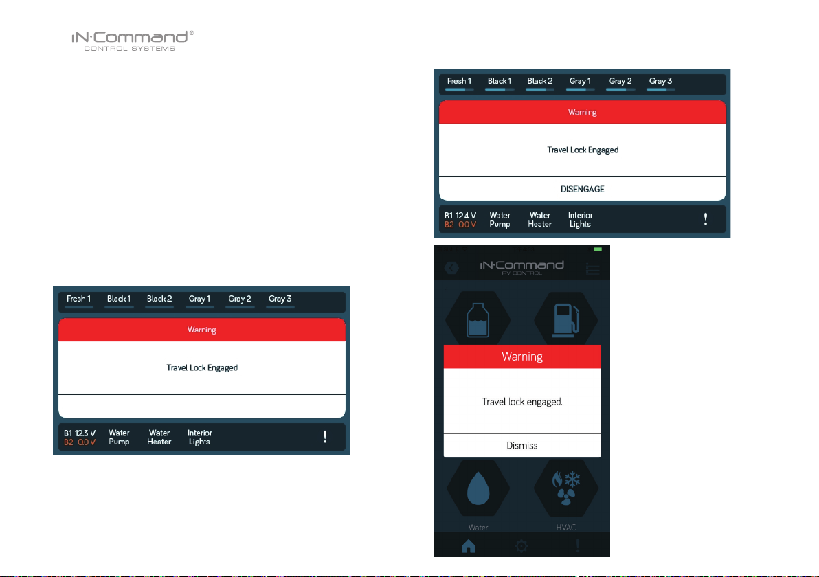
iN-Command is equipped with a Safety Lockout feature to ensure certain
system functions are unavailable during transit.
When the Brake Signal (Towable) or Ignition (Motorized) is activated,
the iN-Command will lock down all motorized functions. The Display
Commander (DC) and mobile devices will also display “Travel Lock
Engaged” and the affected buttons will cease to activate.
The lights, water pump, water heater, and sensors will continue to
function.
To turn the Travel Lock off, press "DISENGAGE" on the Display
Commander (DC), inside the RV, once the brake signal has been
removed.
Travel Lock on the Display Commander
9
Page 11
NCSP35
• OVERRIDE SWITCHES*
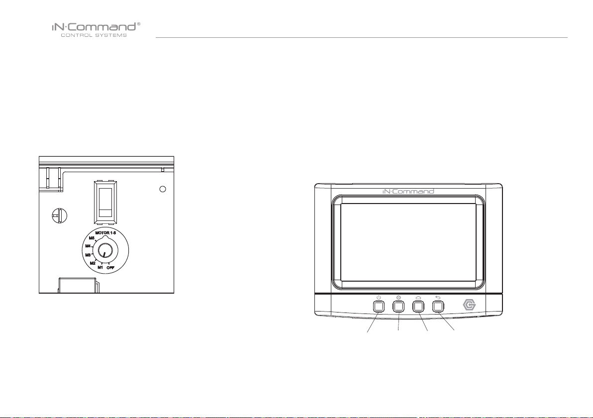
The Body Control Module has an override switch and knob. The
knob below the switch corresponds to a motor function made by the
Display Commander and Handheld Devices App. The switch and
knob actuate all the motor functions on the RV.
To use the override switches, locate the switch on the BCM. Turn
the knob underneath the switch to select the component. Press up
or down on the switch. The switch is momentary and will activate
the component only while pressed in either direction.
• DISPLAY COMMANDER BUTTONS
The DC (Display Commander) has 4 buttons on the front of it.
From left to right, they are:
• Power
• Settings
• Home
• Return
The Power Button turns the DC on and off (long press) and revives
it (short press). The settings button takes you to the settings page.
The Home Button returns you to the Home page. The Return
Button returns you to the previous page.
Power Settings Home Return
10
Page 12

NCSP35
• SPECIFICATIONS
Display Commander (DC)
Operating Voltage . . . . . . . . . . . . . . . . . . . . . . . . . . . . . . 12VDC
Maximum Current Draw . . . . . . . . . . . . . . . . . . . . . 1.5A@9VDC
Minimum Operating Voltage . . . . . . . . . . . . . . .. . . . . . . . 9VDC
Maximum Operating Voltage . . . . . . . . . . . . . . . . . . . . . 16VDC
Body Control Module (BCM)
Operating Voltage . . . . . . . . . . . . . . . . . . . . . . . . . . . . . . 12VDC
Maximum Current Draw . . . . . . . . . . . . . . . . . . . . 4A@12VDC
Minimum Operating Voltage . . . . . . . . . . . . . . . . . . . . . . 9VDC
Maximum Operating Voltage . . . . . . . . . . . . . . . . . . . . . 16VDC
NCSP35 System
EPROM Non-Volatile Memory . . . . . . . . . . . . . . . . . . . . . . YES
Bluetooth Version . . . . . . . . . .. . . . . . . . . . . . . . . . . . . . 4.0 BLE
General
Body Control Module . . . . . . . . 14.9” (W) x 10.4” (D) x 1.8” (H)
Display Commander . .. . . . . . . . . .5.2” (W) x 3.8” (D) x 1.5” (H)
• FCC NOTES
WARNING! Changes or modications to this unit not expressly
approved by the party responsible for compliance could void the
user’s authority to operate the equipment.
NOTE: This equipment has been tested and found to comply with
the limits for a Class B digital device, pursuant to Part 15 of the FCC
Rules. These limits are designed to provide reasonable protection
against harmful interference in a residential installation.
IMPORTANT NOTE:
To comply with the FCC RF exposure compliance requirements,
the antenna(s) used for this transmitter must be installed to provide
a separation distance of at least 20 cm from all persons and must
not be co-located or operating in conjunction with any other
antenna or transmitter. No change to the antenna or the device is
permitted. Any change to the antenna or the device could result in
the device exceeding the RF exposure requirements and void
user’s authority to operate the device.
This equipment generates, uses and can radiate radio frequency
energy and, if not installed and used in accordance with the
instructions, may cause harmful interference to radio communications.
However, there is no guarantee that interference will not occur in a
particular installation. If this equipment does cause harmful interference
to radio or television reception, which can be determined by turning the
equipment off and on, the user is encouraged to try to correct the
interference by one or more of the following measures:
• Increase the separation between the equipment and receiver.
• Connect the equipment into an outlet on a circuit different from that to
which the receiver is connected.
• Consult the dealer or an experienced radio/TV technician for help.
11
Page 13
NCSP35
• PASSCODE PROTECTION
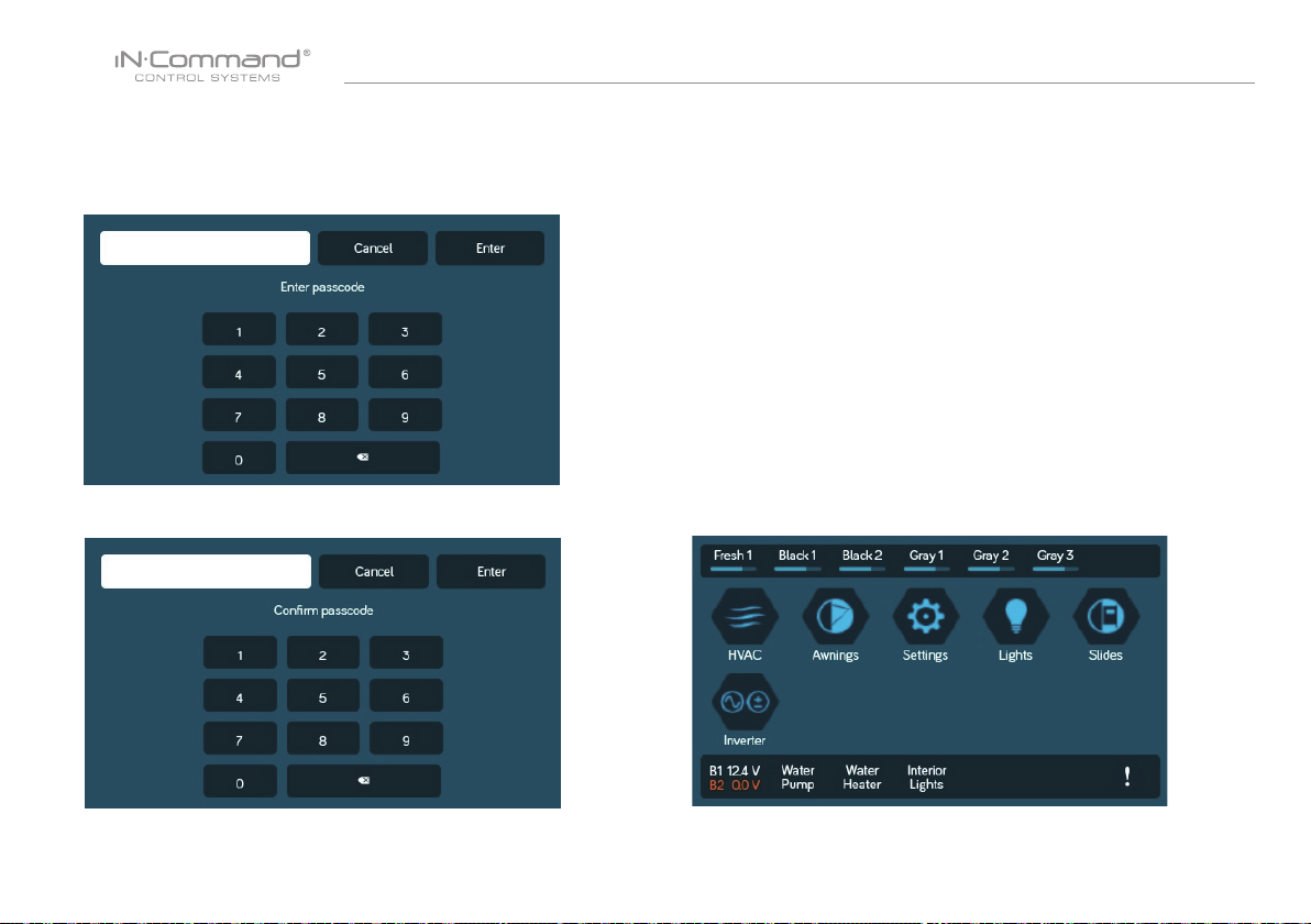
A passcode is required to access the system.
On the rst time use of the system, the user is required to enter
and conrm a new passcode.
Conrm the new passcode.
• SETTINGS
From the Menu screen you can:
• Edit iN-Command function text
• Reposition functions
• Enable/disable functions
• See the status of iN-Command
• Connect devices with Bluetooth
• Change the passcode
• Reset the oor plan
• View iN-Command’s Legal documents and customer
support information.
The Setup button is used by the manufacturer.
• Text Editing*
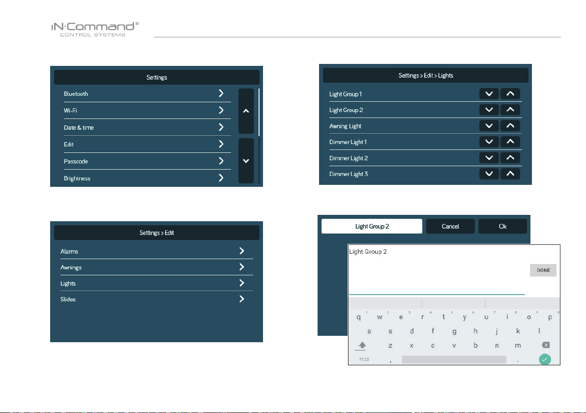
1. Select “Settings”
12
Page 14
NCSP35
2. Press “Edit” to enter Edit page
4. Long press the intended text, e.g., "Light Group 2"
3. Select the function to edit.
5. Use the keyboard to edit the name, then press "Ok"
Note: Editing the text on the DC will not change the text on
a device’s App.
13
Page 15
NCSP35
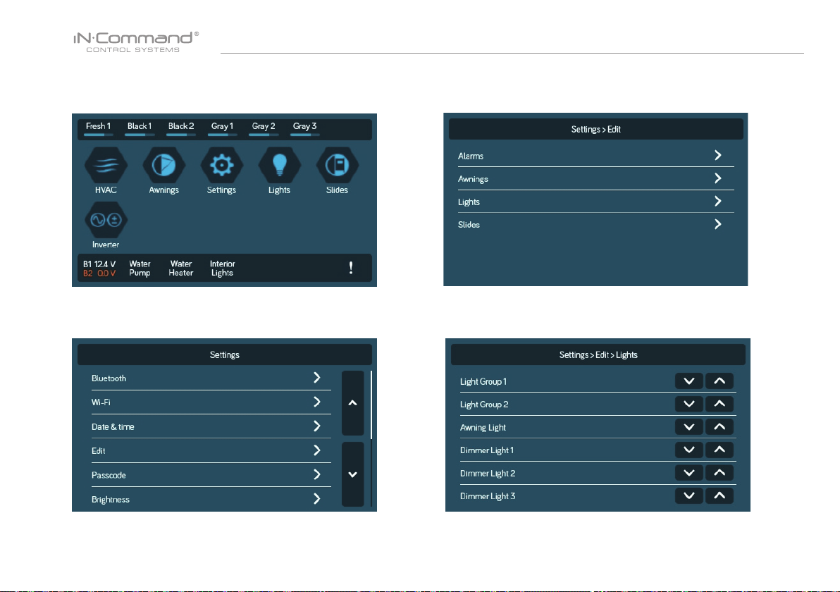
• Scroll List Editing
1. Select " Settings"
3. Select the function to edit.
2. Press “Edit” to enter Edit page
4. Use the Up and Down arrows next to the function to move
the item in the list.
14
Page 16
NCSP35
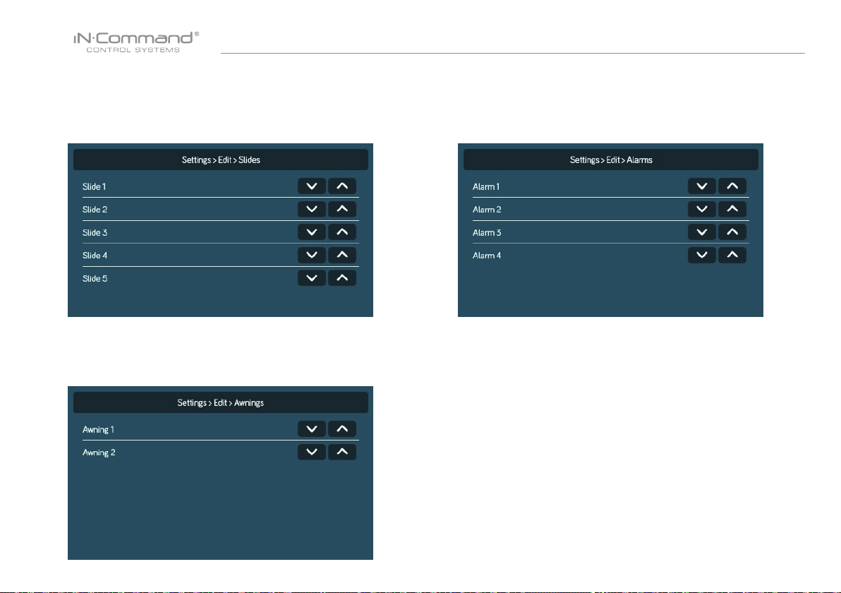
• Slides
Slides can added to the system.
Note: Desired devices need to be correctly wired to the BCM to
function.
• Awning
Awning can added to the system.
Note: Desired devices need to be correctly wired to the BCM to
function.
• Alarm Inputs
Alarm can added to the system.
Note: Desired devices need to be correctly wired to the BCM to
function.
15
Page 17
NCSP35
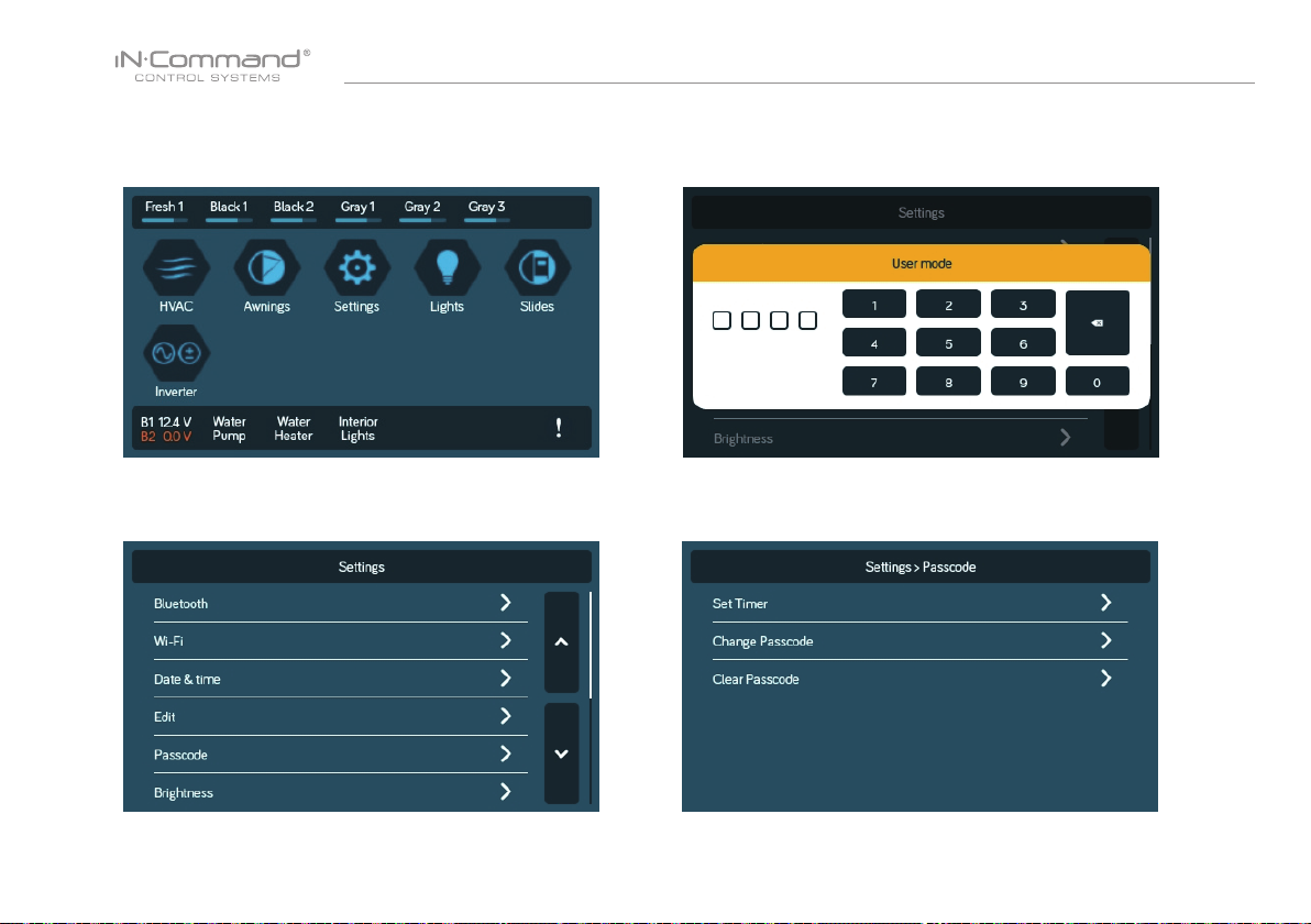
• Passcode
2.1 Enter the correct passcode to proceed.1. Select “Settings”.
2. Press “ Passcode” to enter passcode setup.
3. The passcode setup window will open.
16
Page 18
NCSP35
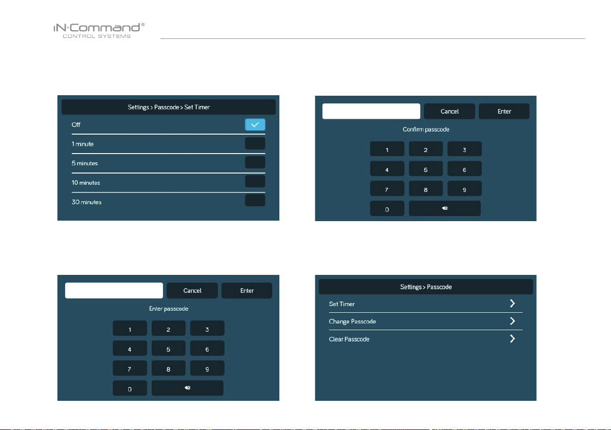
• Set Passcode Timer
Press the “Set Timer” select the idle time to activate the
passcode protection.
• Change Passcode • Clear Passcode
1. Press the “Change Passcode” button to change to a
new passcode.
2. Enter the new passcode
3. Conrm new passcode.
Press the “Clear Passcode” to clear the passcode.
This will restart the App, take the user to the End-User License
Agreement, and have the user setup a new passcode.
17
Page 19
NCSP35
• MOBILE DEVICES:
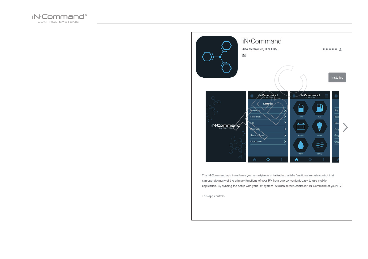
iN-Command is able to pair to Android and iOS devices using
the iN-Command App.
Visit the Google Play and Apple App stores on your mobile
device to download and use the iN-Command App.
Seven mobile devices are able to be paired iN-Command at
one time, but only 1 iOS and 3 Android devices are able to be
actively paired at the same time; meaning, 3 Android devices
and 1 iOS device can all actively control the iN-Command
functions.
To use another device not actively paired to iN-Command, 1
device needs to shut down its iN-Command App to allow another
device to actively pair. To do this simply select the power button
on the App, shut down the App in the device’s settings menu, or
press “DISCONNECT” on the DC’s Connections page.
18
Page 20
NCSP35
• Pairing Mobile Device to DC
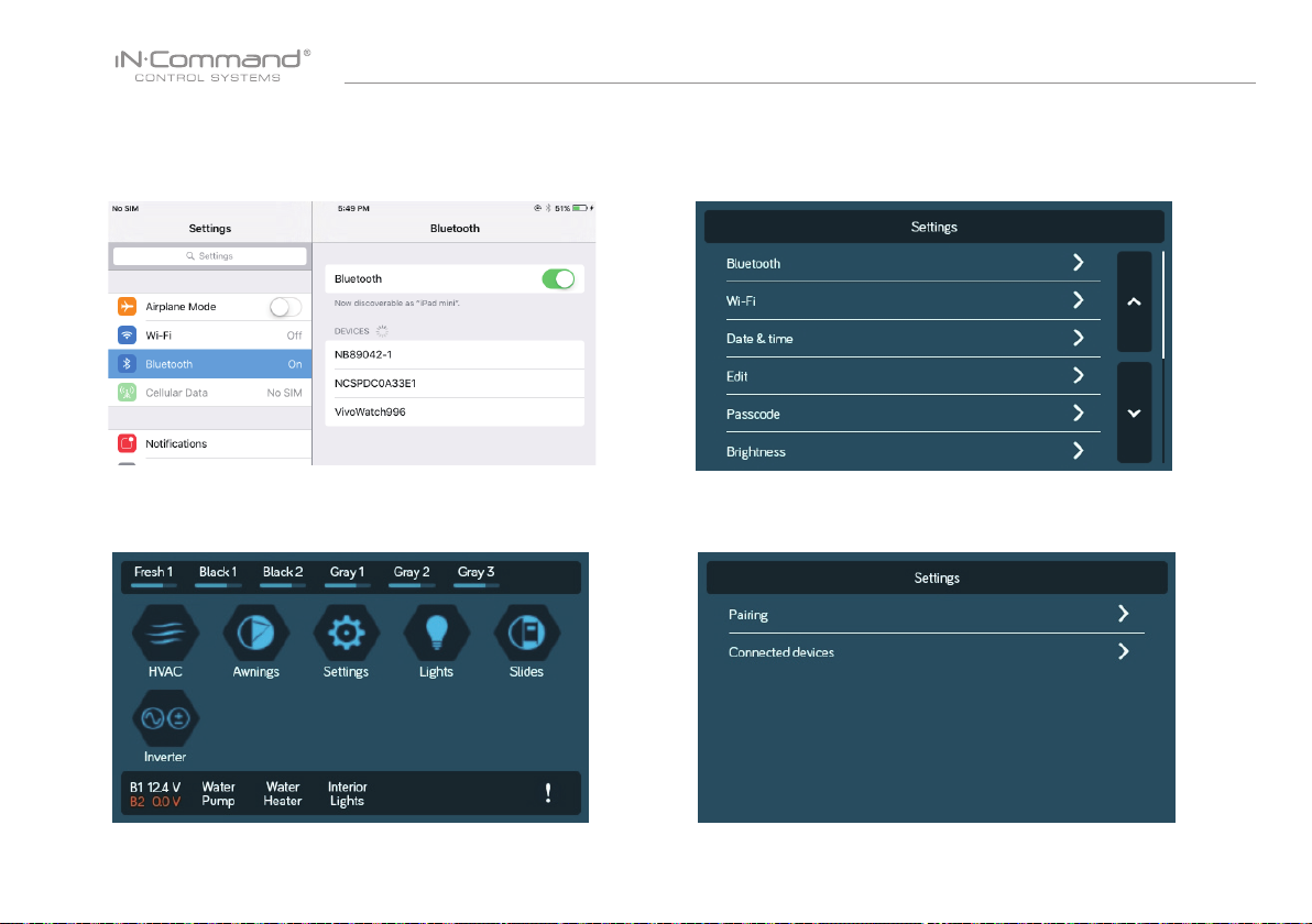
1. Enable "Bluetooth" in the system settings of the mobile device
2. From the DC Home Page, select "Settings" 2.2 Select "Pairing" to pair devices and view current paired devices.
2.1 Select the “ Bluetooth ” tab.
19
Page 21
NCSP35
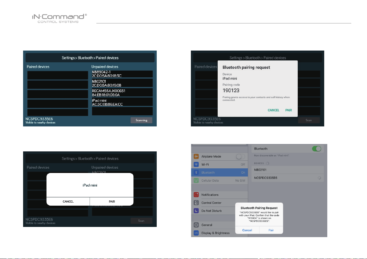
2.3 Press Scan to start scanning for Unpaired devices.
Locate the mobile device in the Unpaired Device list.
Select the device by pressing it.
2.5 A Bluetooth Pairing request will appear on the DC and mobile device.
2.6 Press "PAIR" on the DC.
2.4 A Popup with the device name will apear on the display.
Press "PAIR"
2.7 Press "Pair" on the mobile device.
20
Page 22
NCSP35
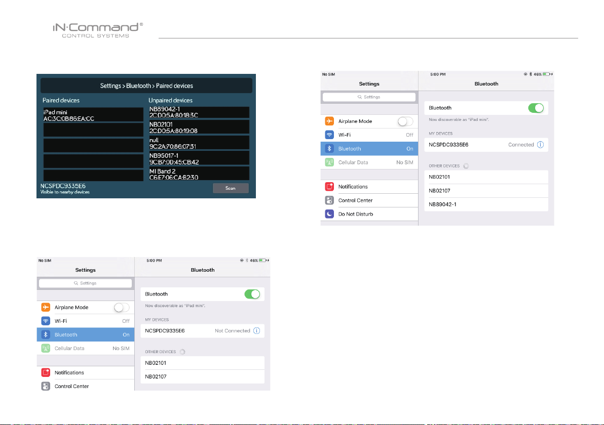
2.8 The mobile device will be displayed in the "Paired devices"
list on the DC
2.9 The DC will be displayed on the mobile device list in the
format " NCSPDCXXXXX". Press the DC on the mobile
device to connect with it.
2.10 The mobile device now shows that the DC is connected.
21
Page 23
NCSP35
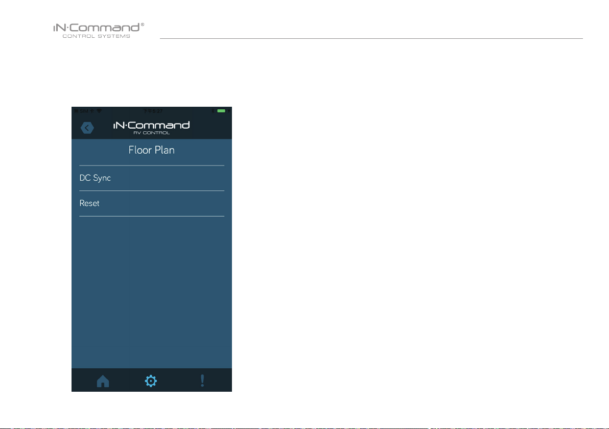
4. Reset Floor Plan
Press the “Reset” button in the Menu page to load the
oor plan conguration from the DC. The current settings
will be lost/replaced.
22
Page 24
NCSP35
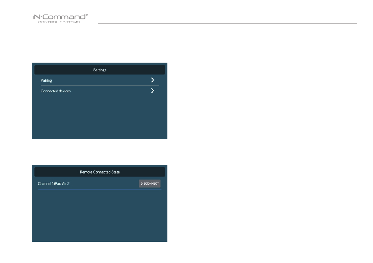
• CHECKING ACTIVE BLUETOOTH SESSION
1. Select “Connected devices”.
2. The page shows information of current active Bluetooth devices.
* To disconnect a handheld device, press “DISCONNECT”, or simply
shut down the device’s App. This function is used to disconnect
a device that is not actively being used, and to allow another
device to be connected.
23
Page 25
NCSP35
• HVAC
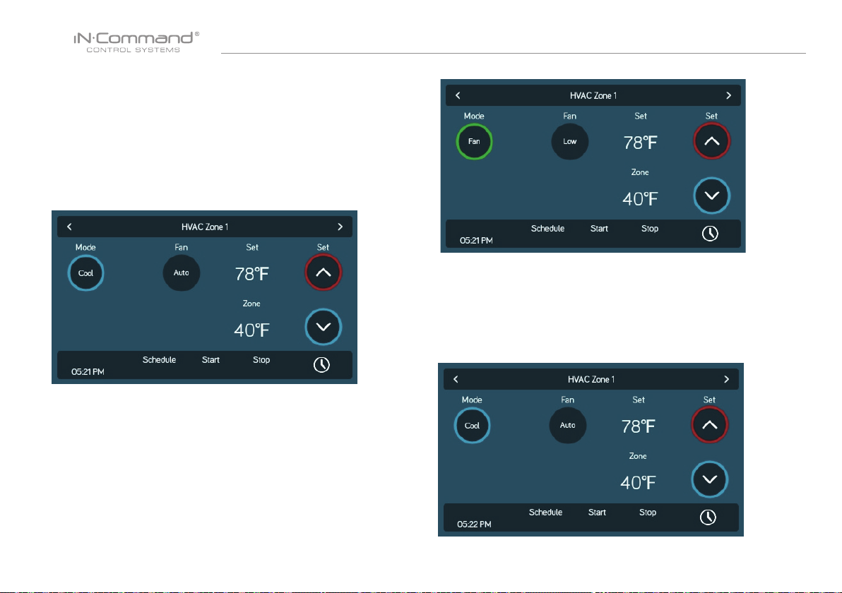
From the HVAC page, you can control the Heating, Ventilation
and Air conditioning functions in the RV.
With iN-Command, you can control up to 4 HVAC zones and
schedule times for the HVAC function to be active.
• Vent Fans
The Vent Fans for each zone can be opened, closed, and
change the fan speed.
• Fan Only Mode
1. To have just the AC fan operating in a zone, select the desired
Zone, the press the "Mode" button to switch to Fan mode.
2. Press the " Fan" button to switch between Low and High fan
speeds.
• AC Cooling
1. Select the desired Zone. Press the "Mode" button to switch to
"Cool" mode.
2. Use the "Set" up and down arrows to set the desired temperature
for the zone.
3. Press the "Fan" button to switch between Low,High and Auto fan speeds.
24
Page 26
NCSP35
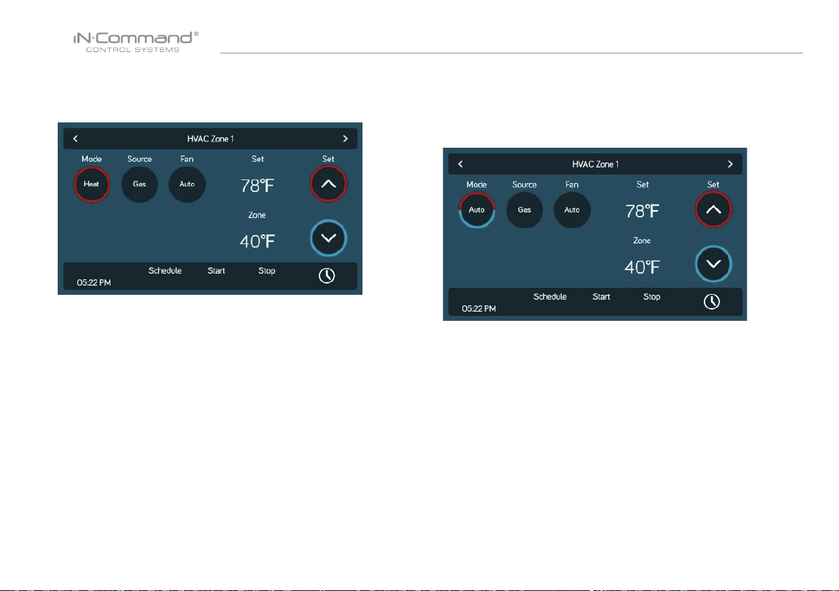
• Heating
1. Select the desired Zone. Press the "Mode" button to switch to
"Heat" mode.
2. Press the "Source" button to select between Gas and Electric.
(Available Heat sources depend on Floor Plan)
3. Use the "Set" up and down arrows to set the desired temperature
for the zone.
4. Press the "Fan" button to switch between Off, Low, High and Auto.
(Off is not available in Electric Heat Source.)
• Auto
Auto Mode will automatically switch between Cool and Heat modes to
reach the desired Set temperature.
(Heat Mode is only available in Zones with Heat Mode selected on
Floor Plan).
1. Select the desired Zone. Press the "Mode" button to switch to
"Auto" mode.
2. Use the "Set" up and down arrows to set the desired temperature
for zthe zone.
3. Press the "Fan" button to switch between Off, Low, High and Auto.
25
Page 27
NCSP35
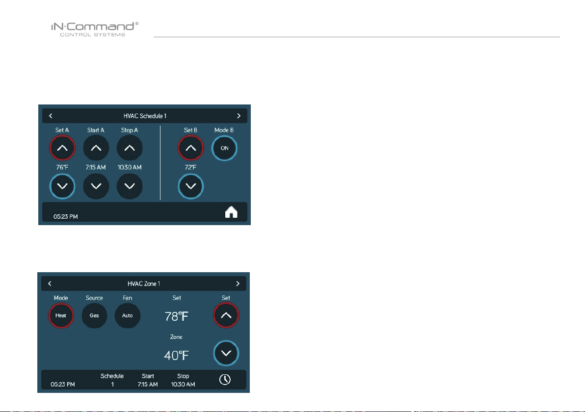
• HVAC Schedule
The Schedule function allows you to set a temperature and choose
a start and stop for when you want the HVAC function to operate.
1. Press the "Clock" icon at the bottom right corner of the
HVAC home screen to enter the Schedule page.
2. Use the "Set" up and down arrows to set the desired temperature.
3. Use the " Start" and "Stop" arrows to set the time frame that you
want the HVAC function to operate.
4. Choose schedule 1 or 2 on HVAC zone Home Page.
26
Page 28
NCSP35
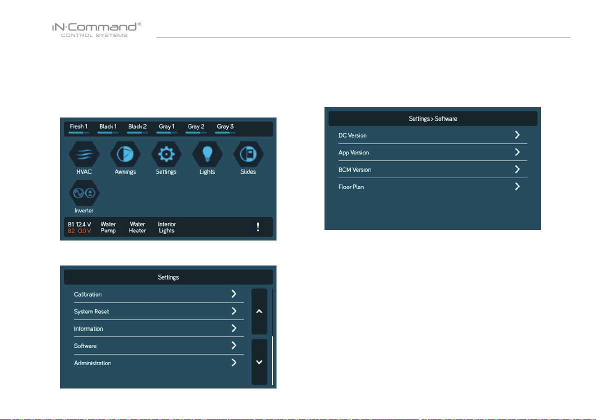
• SOFTWARE UPDATE*
Software updates include oorplan redesigns and App version updates.
1. Insert USB drive loaded with updated software into the USB
port at he bottom of the DC.
2. Select "Settings" enter the Settings page.
3. In the Settings page, select the "Software" tab.
4. In the software page, you can choose to update the Floor Plan,
DC Version, App Version and BCM Versions.
The system will look for specic le names for software updates.
- File name: “NCSP3-DC VXXXX.zip” > DC OS update
(xxxx is the version number)
- File name: “ncspdcap_vxxxx.apk” > DC App update
(xxxx is the version number)
- File name: "NCSPDC3Vxxxx.bin" > BCM update
(xxxx is the version number)
27
Page 29
NCSP35
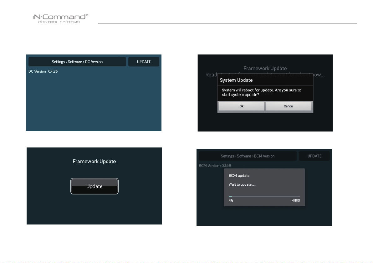
6. Press the DC Version to update the DC OS sytem.
Press "UPDATE"
8. Press "Ok" to continue.
7. Framework update, Press"Update"
9. Press the BCM Version to update the BCM system.
Press "UPDATE"
28
Page 30
NCSP35
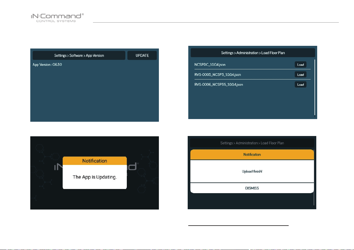
10. Press the App version to update the DC App.
Press " UPDATE"
12. Press the Floor Plan to select a oor plan.
Press "Load" to select the oor plan.
11. Waiting for Update.
13. Press "DISMISS" to conrem selection.
* If a software update is needed, go to
http://www.asaelectronics.com//in-command
** If there is a software issue, Call ASA Electronics Technical
Support at 1-877-845-8750 or email them at [email protected].
29
Page 31
NCSP35
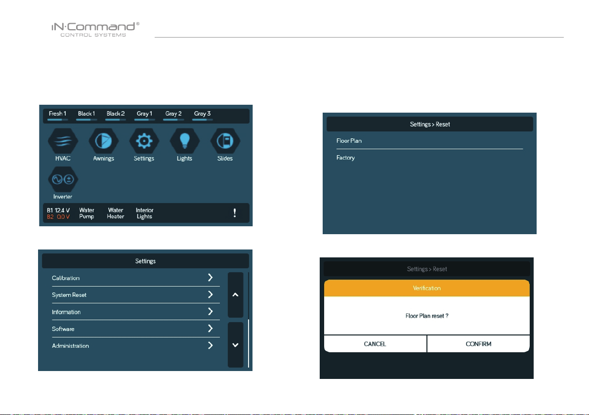
• RESET: FLOOR PLAN
Rest to Floor Plan to remove customization, or reset to factory settings.
1. Select "Settings".
3. Select on of the two options.(Floor Plan of Factory) to restore
to a previous state. Current settings will be lost.
a. Floor Plan: restores to previous oor plan settings from
RV manufacturer.
b. Factory: restores to default settings from ASA electronics.
2. Select “System Reset” in the Settings page.
3. Conrm for oor plan to complete update.
30
Page 32
NCSP35
• TOUCH SCREEN CALIBRATION
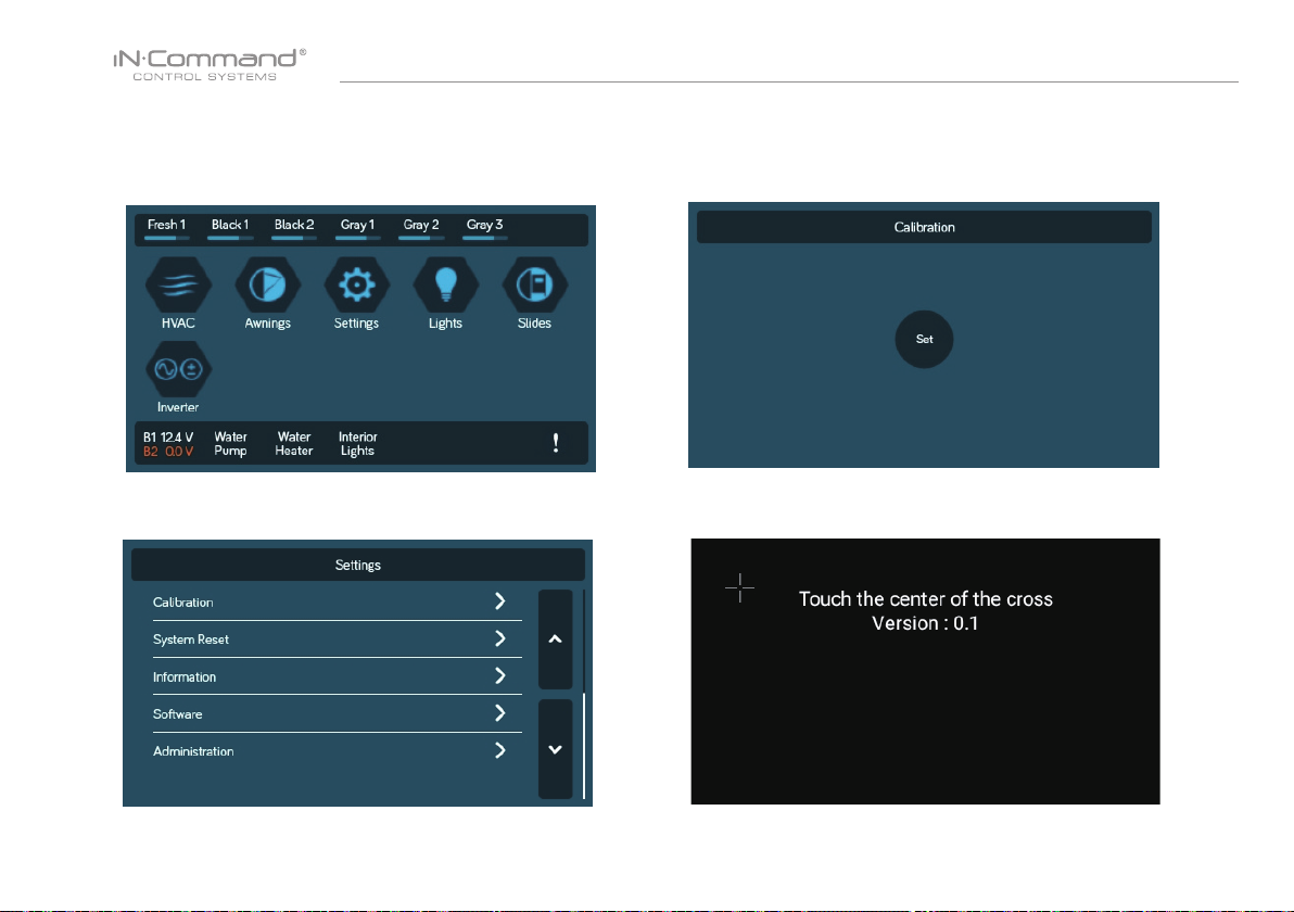
1. Select “Settings”.
3. To calibrate the Touch Screen, select "Set". Follow the
instructions.The DC will restart after calibration.
2. Select “Calibartion”.
4. Touch the center of the cross.
31
Page 33
NCSP35
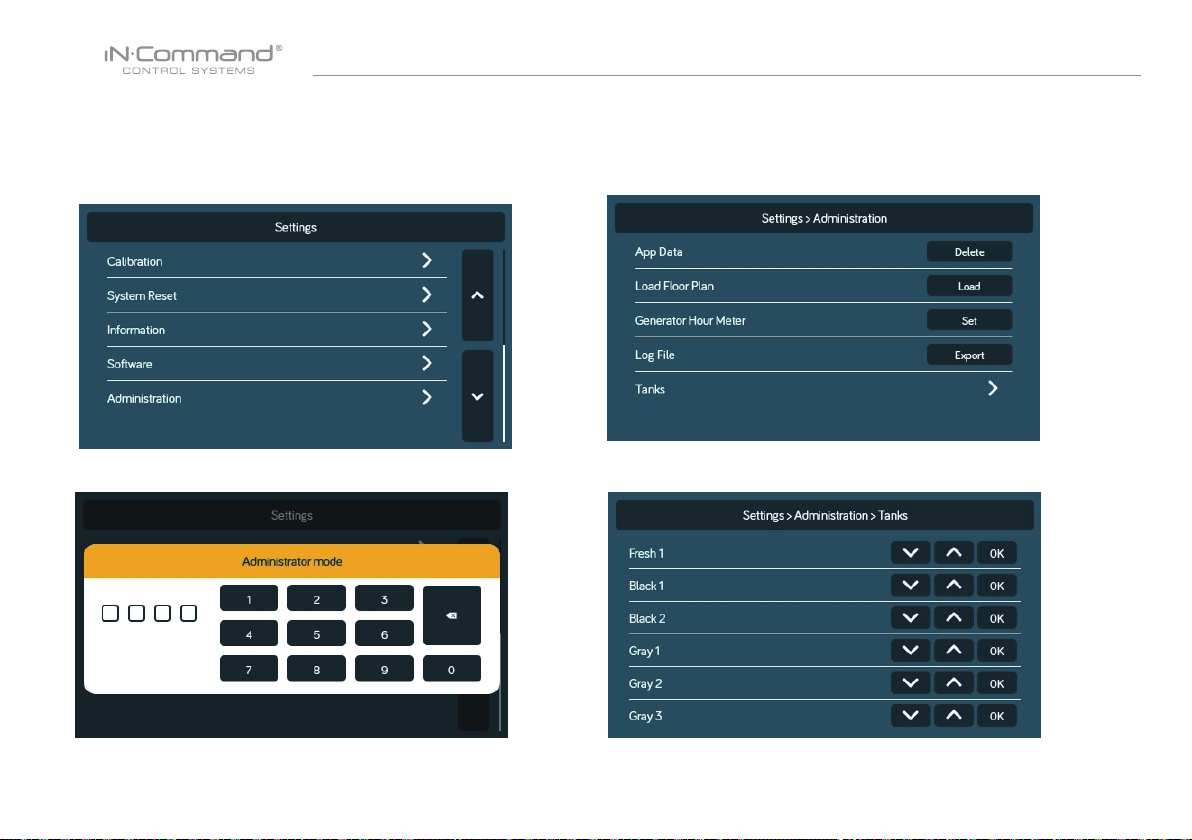
• SYSTEM CALIBRATION*
From the admin page, the App Date can be deleted, the Generator
Hour Meter can be set, and the Water Tanks can be calibrated.
1. From the Settings page, press "Administration".
3. Make Selection.
2. Select “Calibartion”.
4. Select “Tanks” to set resistor reference value for every tank.
32
Page 34
NCSP35
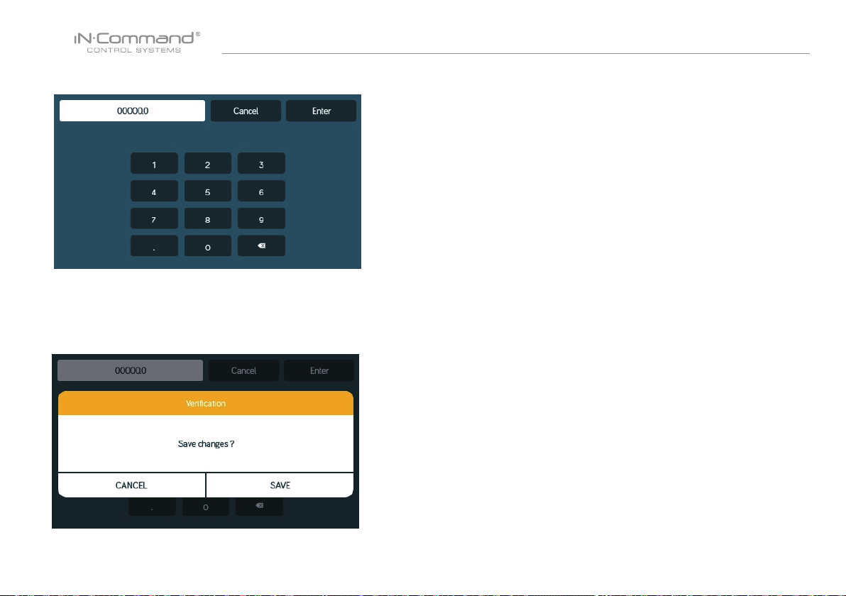
7. Press the Generator Hour Meter "Set" button to set the meter time.
8. Press the App Date "Delete" button to clear current App date.
Note: This will remove the oor plan settings from the RV
Manufacturer.
* The system is calibrated by the manufacturer and should only be
accessed for troubleshooting.
** The Admin Passcode is used by the manufacturer for programming
and troubleshooting purposes. Should there be a calibration issue,
call ASA Electronics Technical Support at 1-877-845-8750 or
email them at [email protected].
33
Page 35
NCSP35
• TROUBLESHOOTING
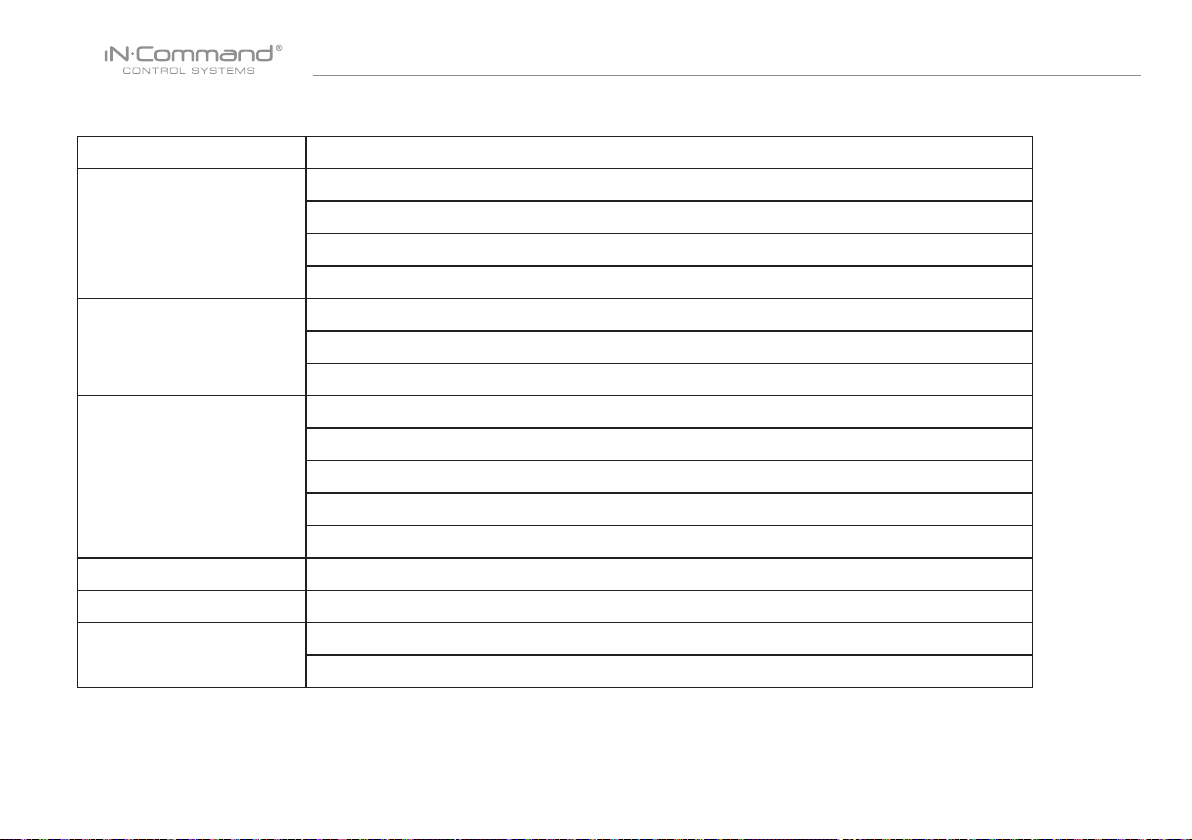
Symptom Solution
Check for +12VDC on Positive (+) input on back of the DC.
Display Commander (DC) will
not power on or no front panel
operation
No Power to the Body Control
Module (BCM)
DC screen ashing on and off
after installation
Motor Functions do not activate Check for +12VDC on pin 41. Ensure the relay activates.*
*Relay not activating Replace the relay with one from an unused circuit. See label on BCM cover for relay identication
DC shows 0V and no functions
activate from DC
Check for Ground on Negative (-) input on back of the DC.
Check fuse in Distribution Panel.
Try cycling power with the power button.
Check for +12VDC on pin 42.
Check for Ground on pin 39.
Check fuse in Distribution Panel.
Disconnect power wires from the back of the DC.
Shut off all power to the DC and BCM.
Reconnect power wires to the DC.
Return power to the DC and BCM
Press Reset button on the BCM
Check to ensure 4 pin RV-C cable is connected to the back of the DC and to the BCM.
Check for shorts in RV-C cable and for loose pins in the connection.
For additional troubleshooting, call ASA Electronics Technical Support at 1-877-845-8750, email [email protected] or
visit our website http://www.asaelectronics.com//in-command.
34
Page 36
NCSP35
Page 37
NCSP35
Page 38

Page 39

www.jensenrvdirect.com
©2015 ASA Electronics LLC
.
MA-1709002-1R
 Loading...