

Page 1
RV CONTROL AND MONITORING SYSTEM
Installation and Operation Manual
Patent # 9,679,644
Page 2

Page 3
Important Safety Information
Read the iN-Command Manual, and these warnings and instructions carefully before using this product. Failure to follow the use
instructions in this owner’s manual, or improper use of the Mobile Application, Display Commander and/or Body Control Module, could
result in personal injury, including death.
Do not operate while vehicle is being driven
used while the vehicle is being driven. Use of the Mobile Application, Display Commander and/or Body Control Module while the vehicle
is being driven is dangerous and may cause personal injury or property damage.
For adult use only.
to be used by persons under the age of 18. Use by children may cause personal injury or property damage.
Operate only when you have a clear line of sight.
slides), unless you have a clear line of sight to the moving part. The Mobile Application, Display Commander or Body Control Module
may be used only if you are giving instructions to, and receiving instructions from, another person at least age 18 or older who can clearly
see the moving part. Failure to follow these instructions may result in serious personal injury or property damage.
Do not operate under the inuence of alcohol or drugs.
Module while under the inuence of alcohol or drugs. Doing so may result in personal injury or property damage.
Avoid moisture.
Use recommended accessories.
accessories.
The Mobile Application, Display Commander and Body Control Module are intended for adult use only, and are not
To reduce the risk of re or electric shock, do not expose this equipment to rain or moisture.
To reduce the risk of re or electric shock and annoying interference, use only the recommended
. The Mobile Application, Display Commander and/or Body Control Module should not be
Do not operate any moving parts (including, but not limited to, awnings, jacks and
Do not operate the Mobile Application, Display Commander or Body Control
Page 4
• TABLE OF CONTENTS
TABLE OF CONTENTS ...........................................................3
INTRODUCTION .....................................................................4
Thank You! .............................................................................4
Features .................................................................................4
Precautions ............................................................................4
Packing List ............................................................................4
INSTALLATION ........................................................................5
Tools and Supplies .................................................................5
Disconnecting the Battery ......................................................5
Selecting the Mounting Location ............................................ 5
Mounting the Display Commander (DC) ................................5
Mounting the Switch Plate (SP) .............................................5
WIRING ...................................................................................6
APP SETUP MENU LIST .........................................................7
TRAVEL LOCKOUT (SAFETY) ..............................................8
TROUBLE SHOOTING ............................................................9
SWITCH PLATE BUTTONS ..................................................10
DISPLAY COMMANDER BUTTONS .....................................10
SPECIFICATIONS .................................................................11
Federal Communications Commission (FCC) Statement ...... 11
MOBILE DEVICES: ...............................................................12
Pairing Mobile Device to DC/SP ............................................13
NCS50DC/SP FIRMWARE UPDATE* ...................................15
EDIT AND RESET FLOOR PLAN .........................................16
3
Page 5
• INTRODUCTION
• Thank You!
Thank you for choosing iN-Command. We hope you will nd the instructions in this owner’s manual clear and easy to follow. If you take a few
minutes to look through it, you’ll learn how to use all the features of your
new iN-Command Lite for maximum enjoyment.
• Features
Features of iN-Command Lite system:
• Simultaneous control by one Android Device or one iOS Device
• Control one Light zone
• Control Awning
• Control Electric Slides
• Control Jacks (non-automatic function)
• Monitor Battery Voltage with Low Voltage Alert
• Precautions
Use the Proper Power Supply.
•
This product is designed to operate with a 12 volt DC, negative ground
battery system (the standard system in a North American vehicle).
Use Authorized Service Centers
•
Do not attempt to disassemble or adjust this precision product; contact
a professional for assistance.
Avoid Moisture.
•
To reduce the risk of re or electric shock, do not expose this equipment
to rain or moisture.
Avoid Cleaning Products.
•
The front of this unit should only be cleaned with a slightly damp cloth.
Do not use cleaning products.
Use Recommended Accessories.
•
TO REDUCE THE RISK OF FIRE OR ELECTRIC SHOCK AND
ANNOYING INTERFERENCE, USE ONLY THE RECOMMENDED
ACCESSORIES.
.
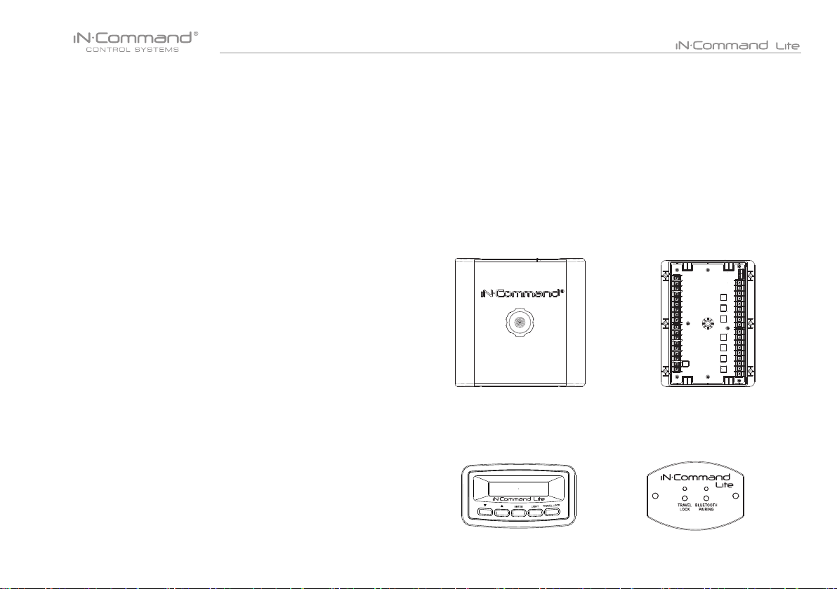
• Packing List
(1) Cover, (1) Thumb Screws (1) Body Control Module (BCM)
(1) Display Commander (DC)
(1) Switch Plate (SP)
4
Page 6
• INSTALLATION
It’s a good idea to read all of the instructions before beginning the
installation. We recommend having your iN-Command system
installed by a reputable RV dealership
• Tools and Supplies
You will need the following:
• Phillips screwdriver
• #2 square drive bit
• Wire cutters and strippers
• Electrical tape
• Volt meter/test light
• Crimping tool
• Fork Crimp connectors
• 10 gauge wire for power and slide connections
• 14 and 18 gauge wire for all other connections
• Two #8 PH (0.164” x 0.5”) screws for the DC
• Two #8 PH (0.164” x 0.5”) screws for the SP
• Six #8 PH (0.164” x 1.0”) screws for the BCM
• Minimum of 24 gauge wire required to Connect DC To BCM
• Disconnecting the Battery
To prevent a short circuit, be sure to turn off 12V power and remove
the negative (-) battery cable prior to installation.
• Mounting the Display Commander (DC)
• Cut/Drill hole, allowing space below for future programming and
behind for ventilation
• Route wires through the hole and connect
• Attach rear plate with screws
• Check and ensure correct operation
• Snap main unit into plate
• Mount the unit using two #8 PH (0.164” x 0.5”) screws
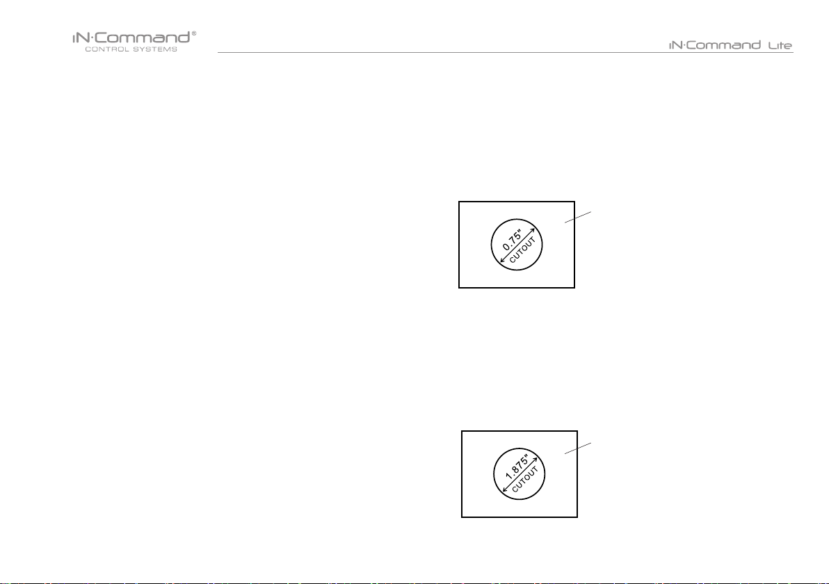
Wall For Reference
HOLE SIZES
Display Commander (DC) 0.75”
Recommended Cutout
• Mounting the Switch Plate (SP)
• Cut/Drill hole, allowing space below for future programming and
behind for ventilation
• Route wires through the hole and connect
• Check and ensure correct operation
• Mount the unit using two #8 PH (0.164” x 0.5”) screws
• Selecting the Mounting Location
Select a mounting location, taking care to avoid the following:
• Places exposed to heat-radiating appliances such as electric heaters
• Adjacent to other equipment that radiates heat
• Under thermostats
• Poorly-ventilated or dusty places
• Moist or humid locations
5
Wall For Reference
HOLE SIZES
Switch Plate (SP) 1.875”
Recommended Cutout
Page 7

• WIRING
The wiring diagram depicts all the wiring connections required for proper operation of the unit.
The TX (transmit) and RX (receive) connections at each device are crossed (crossover cable).
BODY CONTROL MODULE (BCM) CONNECTIONS
PIN NO. WIRE GAUGE DESCRIPTION
1 10 AWG M1 OUT 12V (12V FOR M1 EXTEND)
2 10 AWG M1 IN 12V (12V FOR M1 RETRACT)
3 10 AWG M2 OUT 12V (12V FOR M2 EXTEND)
4 10 AWG M2 IN 12V (12V FOR M2 RETRACT)
5 10 AWG M3 OUT 12V (12V FOR M3 EXTEND)
6 10 AWG M3 IN 12V (12V FOR M3 RETRACT)
7 10 AWG M4 OUT 12V (12V FOR M4 EXTEND)
8 10 AWG M4 IN 12V (12V FOR M4 RETRACT)
9 10 AWG M5 OUT 12V (12V FOR M5 EXTEND)
10 10 AWG M5 IN 12V (12V FOR M5 RETRACT)
11 10 AWG M6 OUT 12V (12V FOR M6 EXTEND)
12 10 AWG M6 IN 12V (12V FOR M6 RETRACT)
13 10 AWG M7 OUT 12V (12V FOR M7 EXTEND)
14 10 AWG M7 IN 12 V (12V FOR M7 RETRACT)
15 16 AWG TRAVEL LOCK 12V IN
16 14 AWG LIGHT GROUP 12V IN
17 14 AWG LIGHT GROUP GND
18 14 AWG LIGHT GROUP 12V OUT
19 14 AWG LIGHT GROUP SWITCH INPUT 12V
20 10 AWG MOTOR 7 GND OUT (M7 IN)
PIN NO. WIRE GAUGE DESCRIPTION
21 10 AWG MOTOR 7 12V OUT 30 AMP (M7 OUT)
22 10 AWG MOTOR 6 GND OUT (M6 IN)
23 10 AWG MOTOR 6 12V OUT 30 AMP (M6 OUT)
24 10 AWG MOTOR 5 GND OUT (M5 IN)
25 10 AWG MOTOR 5 12V OUT 30 AMP (M5 OUT)
26 10 AWG MOTOR 4 GND OUT (M4 IN)
27 10 AWG MOTOR 4 12V OUT 30 AMP (M4 OUT)
28 10 AWG MOTOR 3 GND OUT (M3 IN)
29 10 AWG MOTOR 3 12V OUT 30 AMP (M3 OUT)
30 10 AWG MOTOR 2 GND OUT (M2 IN)
31 10AWG MOTOR 2 12V OUT 30 AMP (M2 OUT)
32 10 AWG MOTOR 1 GND OUT (M1 IN)
33 10 AWG MOTOR 1 12V OUT 30 AMP (M1 OUT)
34 10 AWG CHASSIS GND (IN)
35 10 AWG MOTOR FEED 12V (IN)
36 10 AWG BCM 12V (IN)
37 24 AWG 12V OUT (CONNECT TO DC)
38 24 AWG TX (CONNECT TO DC RX)
39 24 AWG RX (CONNECT TO DC TX)
40 24 AWG GND OUT (CONNECT TO DC)
6
Page 8

• APP SETUP MENU LIST
One light group and seven motor functions can be added or removed
via a downloadable App from Google and Apple stores.
Motor functions may include slides, awnings, jacks, or any motor that
may be controlled with a momentary switch.
Refer to the Wiring Diagram and Terminal List when installing new
equipment.
ITEM SELECTION
Light Group 1 No, Yes
Motor 1 No, Yes
Motor 2 No, Yes
Motor 3 No, Yes
Motor 4 No, Yes
Motor 5 No, Yes
Motor 6 No, Yes
Motor 7 No, Yes
7
Page 9

• TRAVEL LOCKOUT (SAFETY)
iN-Command is equipped with a Travel Lockout feature to
ensure certain system functions are unavailable during transit.
When the Brake on the vehicle is activated, iN-Command will
lock out (disable) all motorized functions. If the Switch Plate
(SP) is installed, the Travel Lock LED will be solid red.
If the DC is installed, Travel Lock text will appear.
Mobile devices will display Travel Lockout in Orange text and
motor functions will cease to actuate and Disabled will appear
on the buttons.
The light control will continue to function.
To turn the Travel Lock off press the “Travel Lock” button on
the Display Commander or Switch Plate inside the RV.
Travel Lock on a handheld device app
Travel Lock on the Display Commander
8
Travel Lock on the Switch Plate
Page 10

• TROUBLE SHOOTING
Symptom Solution
Verify the BCM is powered on.
Display Commander (DC)
will not turn ON
No power to the Body
Control Module (BCM)
DC screen ashing on and
off after installation
Light Group is not working.
Motor functions are not working Check 12V+ at pin 35.
Travel Lock is on Ensure 12V+ is removed from Pin 15.
Functions not operating from
DC or App and App shows 0V
If an issue is unable to be resolved using the above methods, contact ASA Electronics Technical
Support at 1-877-845-8750 or email them at info@asaelectronics.com
Check main fuse in Distribution Panel.
Check 12V+ on wire to DC (RED wire).
Check Ground wire to DC.
Check if the Red power LED is off,
Check the fuse in the Distribution Panel.
Check 12V+ on wire at pin 36. Check Ground wire at pin 34.
Cycle power to the BCM and DC.
Ensure the wires to the BCM and DC are connected and there is 12V.
Ensure the wires to the BCM and DC are not damaged or pinched.
Ensure the Battery is charged.
Cycle power to the BCM and DC.
Ensure wires are making contact with pins and 12V+ is present.
Check 12V+ at Pin 16.
Check fuse in the Distribution Panel.
Check to ensure RX & TX wires connected properly.
9
Page 11

• SWITCH PLATE BUTTONS
The SP (Switch Plate) has 2 buttons on the front of it.
From left to right, they are:
• Travel Lock
• Bluetooth Pairing
The Travel Lock button turns off the Travel Lock function when the
light is ashing red. The Bluetooth Pairing button is used to pair
and unpair the mobile app to and from the SP.
• DISPLAY COMMANDER BUTTONS
The DC (Display Commander) has 5 buttons on the front of it.
From left to right, they are:
• Down
• Up
• Enter
• Light
• Travel Lock
The Down button navigates down through the Function Menu.
The Up button navigates up through the Function Menu.
Enter button is used to engage motor functions, pair mobile app,
and execute menu commands. The Light button turns on/off the
light group with a quick press and release. Press and hold the Light
button to turn the display back light on/off.
10
Page 12

• SPECIFICATIONS
NCS50DC (Display Commander)
Operating Voltage . . . . . . . . . . . . . . . . . . . . . . . . . . . . . . . . 12VDC
Maximum Current Draw . .. . . . . . . . . . . . . . . .. . . .200mA@12VDC
Minimum Operating Voltage . . . . . . . . . . . . . . . . . . . . . . . . . 9VDC
Maximum Operating Voltage . . . . . . . . . . . . . . . . . . . . . . . . 16VDC
NSC50 (Body Control Module)
Operating Voltage . . . . . . . . . . . . . . . . . . . . . . . . . . . . . . . . 12VDC
Maximum Current Draw . . . . . . . . . . . . . . . . . . . . . . . 1A@12VDC
Minimum Operating Voltage .. . . . . . . . . . . . . . . . . . . . . . . . 9VDC
Maximum Operating Voltage .. . . . . . . . . . . . . . . . . . . . . . . 16VDC
NCS50SP (Switch Plate)
Operating Voltage . . . . . . . . . . . . . . . . . . . . . . . . . . . . . . . 12VDC
Maximum Current Draw . . . . . . . . . . . . . . . . . . . 200mA@12VDC
Minimum Operating Voltage . . . . . . . . . . . . . . . . . . . . . . . . 9VDC
Maximum Operating Voltage . . . . . . . . . . . . . . . . . . . . . . . 16VDC
System
EPROM Non-Volatile Memory . . .. . . . . . . . . . . . . . . . . . . . . YES
Bluetooth Version . . . . . . . . . . . . . . . . . . . . . . . .. . . . . . . 4.0 BLE
General
Body Control Module . . . . . . .. . . . . 14.9” (W) x 10.4” (D) x 1.8” (H)
Display Commander . . . . . . . . . . . . . 3.8” (W) x 1.2” (D) x 2.1” (H)
Switch Plate…….... .. . . . . . . . . . . . . . 3.2” (W) x 1.2” (D) x 2.3” (H)
• Federal Communications Commission (FCC) Statement
15.21
You are cautioned that changes or modications not expressly approved
by the part responsible for compliance could void the user’s authority to
operate the equipment.
15.105(b)
This equipment has been tested and found to comply with the limits for
a Class B digital device, pursuant to part 15 of the FCC rules. These
limits are designed to provide reasonable protection against harmful
interference in a residential installation.
This equipment generates, uses and can radiate radio frequency energy
and, if not installed and used in accordance with the instructions, may
cause harmful interference to radio communications. However, there is
no guarantee that interference will not occur in a particular installation.
If this equipment does cause harmful interference to radio or television
reception, which can be determined by turning the equipment off and on,
the user is encouraged to try to correct the interference by one or more
of the following measures:
- Reorient or relocate the receiving antenna.
- Increase the separation between the equipment and receiver.
- Connect the equipment into an outlet on a circuit different from that to
which the receiver is connected.
- Consult the dealer or an experienced radio/TV technician for help.
This device complies with Part 15 of the FCC Rules. Operation is
subject to the following two conditions:
1) this device may not cause harmful interference and
2) this device must accept any interference received, including
interference that may cause undesired operation of the device.
FCC RF Radiation Exposure Statement:
1.This Transmitter must not be co-located or operating in conjunction
with any other antenna or transmitter.
2.This equipment complies with FCC RF radiation exposure limits set
forth for an uncontrolled environment.
3.This equipment should be installed and operated with a minimum
distance of 20 centimeters between the radiator and your body.
11
Page 13

• MOBILE DEVICES:
iN-Command Lite is able to pair to Android and iOS devices via
the mobile App.
Visit the Google Play and Apple App stores on your mobile
device to download and use the iN-Command Lite App.
Only One mobile device is able to be paired with
iN-Command Lite.
12
Page 14

• Pairing Mobile Device to DC/SP
1. Open NCS Lite application on device.
3. Press “Select” button to connect the SP or DC.
4. Press device name to connect.2. Press the gear cog to enter the settings page.
13
Page 15

5. Remote device will show pairing message.
The SP will ash a blue light.
The DC will ash " Accept new device on display"
Press "ENTER" or "BLUETOOTH PAIRING" button to Pair.
6. If connection is successfully established, setting page
will show connected device name and versions.
To connect NCS50DC/SP with another device.
NCS50SP :
Long press“BLUETOOTH PAIRING” button for 7~10 seconds to unpair
device. If unpairing is successful, NCS50SP will ash blue light twice.
repeat steps 2~7 for connecting another device
NCS50DC:
In DC Menu, select unpair device and press the enter button.
A message of "ARE YOU SURE?" will appear.
Press "ENTER" button Again.
14
ON APP:
When powering down the App select the box to "Unpair Device"
Page 16

• NCS50DC/SP FIRMWARE UPDATE*
1. Press “Update” button to update NCS50DC/NCS50SP.
2.2 For Android: Wait for Wi-Fi connection, then press start button.
2.1 For iOS: In Wi-Fi Settings, connect to Wi-Fi network shown on app.
Password is “1234567890”.
15
3. For iOS : Once connected to network, go back to app, App will
automatically start rmware update.
Page 17

4. App will display "Update complete" once rmware is update
Press Dismiss button. DC/SP will reboot with new rmware.
5. BCM update: Press update button next to BCM version.
BCM update will begin automatically.
• EDIT AND RESET FLOOR PLAN
1. From the Apps Home Page, press the gear cog at the lower
right corner to enter the Settings Page.
2. From the Settings Page, you can "Edit Menu", "Load Default Menu",
"Load DC Menu" and "Push Settings to DC Menu".
** DO NOT LEAVE APP ONCE
UPDATE HAS STARTED**
Update will take 10 minutes.
16
Page 18

3. To Edit the oor plan, press the Edit button.
5. To add or remove functions, press the box next to the function.
4. In the Edit Menu, you can add or remove functions,
reposition function and edit the text for the function.
6. To reposition a function, press and hold the "≡" icon next to the
function. Drag to move the function to a new location.
The "Light" function is shown as an example.
17
Page 19

7. To edit the text, press on the function text. A device rename
window will open. Press "OK" after completing text editing.
(The text box is Limited to 12 characters)
8. Once changes have been made, press the Save button at the
top of the page.
9. After the oor plan has been edited, the new oor plan settings
can be pushed to the DC/SP. Press "Set" Push Settings to DC
Menu".
10. After the new oor plan settings have been pushed to the DC/SP,
another device can retrieve edited oor plan by pressing the
"Load" button next to "Load DC Menu".
11. To go back to the default oor plan settings, press the "Load"
button next to " Load Default Menu ".
18
Page 20

www.jensenrvdirect.com
©2015 ASA Electronics LLC
.
MA-1612004A-1R
 Loading...