


INSTRUCTION MANUAL
DSP COLOR CAMERA
1/3" INTERLINE TRANSFER CCD
STANDARD RESOLUTION
HIGH RESOLUTION
Please read this manual thoroughly before use, and keep it handy for future reference.

ii
ISSUE 1 – MAY 2001

iii
WARNINGS AND CAUTIONS
TO REDUCE THE RISK OF FIRE OR ELECTRIC SHOCK, DO NOT
EXPOSE THIS PRODUCT TO RAIN OR MOISTURE. DO NOT INSERT
ANY METALLIC OBJECTS THROUGH THE VENTILATION GRILLS OR
OTHER OPENINGS ON THE EQUIPMENT.
CAUTION
EXPLANATION OF GRAPHICAL SYMBOLS
The lightning flash with arrowhead symbol, within an
equilateral triangle, is intended to alert the user to the
presence of uninsulated “dangerous voltage” within the
product’s enclosure that may be of sufficient magnitude to
constitute a risk of electric shock to persons.
The exclamation point within an equilateral triangle is
intended to alert the user to the presence of important
operating and maintenance (servicing) instruction in the
literature accompanying the product.

iv
FCC COMPLIANCE STATEMENT
INFORMATION TO THE USER: THIS EQUIPMENT HAS BEEN TESTED
AND FOUND TO COMPLY WITH THE LIMITS FOR A CLASS B DIGITAL DEVICE,
PURSUANT TO PART 15 OF THE FCC RULES. THESE LIMITS ARE DESIGNED TO
PROVIDE REASONABLE PROTECTION AGAINST HARMFUL INTERFERENCE IN A
RESIDENTIAL INSTALLATION. THIS EQUIPMENT GENERATES, USES AND CAN
RADIATE RADIO FREQUENCY ENERGY AND, IF NOT INSTALLED AND USED IN
ACCORDANCE WITH THE INSTRUCTIONS, MAY CAUSE HARMFUL INTERFERENCE
TO RADIO COMMUNICATIONS. HOWEVER, THERE IS NO GUARANTEE THAT
INTERFERENCE WILL NOT OCCUR IN A PARTICULAR INSTALLATION. IF THIS
EQUIPMENT DOES CAUSE HARMFUL INTERFERENCE TO RADIO OR TELEVISION
RECEPTION, WHICH CAN BE DETERMINED BY TURNING THE EQUIPMENT OFF
AND ON, THE USER IS ENCOURAGED TO TRY TO CORRECT THE INTERFERENCE
BY ONE OR MORE OF THE FOLLOWING MEASURES:
- REORIENT OR RELOCATE THE RECEIVING ANTENNA
- INCREASE THE SEPARATION BETWEEN THE EQUIPMENT AND
RECEIVER
- CONNECT THE EQUIPMENT INTO AN OUTLET ON A CIRCUIT DIFFERENT FROM
THAT TO WHICH THE RECEIVER IS CONNECTED
- CONSULT THE DEALER OR AN EXPERIENCED RADIO/TV TECHNICIAN
FOR HELP
CAUTION: CHANGES OR MODIFICATIONS NOT EXPRESSLY APPROVED BY
THE MANUFACTURED COULD VOID THE USER'S AUTHORITY TO OPERATE THE
EQUIPMENT.
THIS CLASS B DIGITAL APPARATUS COMPLIES WITH CANADIAN ICES-003.
CET APPAREIL NUMÉRIQUE DE LA CLASSE B EST CONFORME À LA NORME NMB003 DU CANADA.

v
IMPORTANT SAFEGUARDS
1. READ AND RETAIN INSTRUCTIONS
Read the instruction manual before operating
the equipment. Retain the manual for future
reference.
2. CLEANING
Turn the unit off and unplug from the power
outlet before cleaning. Use a damp cloth for
cleaning. Do not use harsh cleansers or
aerosol cleaners.
3. ATTACHMENTS
Do not use attachments unless recommended
by manufactured as they may affect the
functionality of the unit and result in the risk of
fire, electric shock or injury.
4. MOISTURE
Do not use equipment near water or other
liquids.
5. ACCESSORIES
Equipment should be installed in a safe, stable
location. Any wall or shelf mounting accessory
equipment should be installed using the
manufacture’s instructions. Care should be
used when moving heavy equipment. Quick
stops, excessive force, and uneven surfaces
may cause the equipment to fall causing
serious injury to persons and objects.
6. VENTILATION
Openings in the equipment, if any, are provided
for ventilation to ensure reliable operation of the
unit and to protect if from overheating. These
openings must not be blocked or covered
7. POWER SOURCES
The equipment should be operated only from
the type of power source indicated on the
marking label. If you are not sure of the type of
power supplied at the installation location,
contact your dealer. For equipment designed to
operate from battery power, refer to the
operating instructions.
8. GROUNDING OR POLARIZATION
Equipment that is powered through a polarized
plug (a plug with one blade wider
than the other) will fit into the power outlet only
one way. This is a safety feature. If you are
unable to insert the plug fully into the outlet, try
reversing the plug. Do not defeat the safety
purpose of the polarized plug.
Alternate Warning: If the equipment is powered
through a three-way grounding-type plug, a plug
having a third (grounding) pin, the plug will only
fit into a grounding-type power outlet. This is a
safety feature. Do not defeat the safety purpose
of the grounding-type plug. If your outlet does
not have the grounding plug receptacle, contact
your local electrician.
9. CORD AND CABLE PROTECTION
Route power cords and cables in a manner to
protect them from damage by being walked on
or pinched by items places upon or against
them.
10. LIGHTNING
For protection of the equipment during a
lightning storm or when it is left unattended
and unused for long periods of time, unplug
the unit from the wall outlet. Disconnect any
antennas or cable systems that may be
connected to the equipment. This will prevent
damage to the equipment due to lightning or
power-line surges.
11. OVERLOADING
Do not overload wall outlets and extension
cords as this can result in a risk of fire or
electric shock.
12. SERVICING
Do not attempt to service the video monitor or
equipment yourself as opening or removing
covers may expose you to dangerous voltage
or other hazards. Refer all servicing to
qualified service personnel.

vi
13. DAMAGE REQUIRING SERVICE
Unplug the equipment from the wall outlet
and refer servicing to qualified service
personnel under the following conditions:
A. When the power supply cord or the
plug has been damaged.
B. If liquid has spilled or objects have
fallen into the unit.
C. If the equipment has been exposed to
water or other liquids.
D. If the equipment does not operate
normally by following the operating
instructions, adjust only those controls
that are covered by the operating
instructions. Improper adjustment of
other controls may result in damage to
the unit.
E. If the equipment has been dropped or
the casing damaged.
F. When the equipment exhibits a distinct
change in performance.
14. REPLACEMENT PARTS
When replacement parts are required, be
sure the service technician uses
replacement parts specified by the
manufacturer or that have the same
characteristics as the original part.
Unauthorized substitutions may result in fire,
electric shock, or other hazards.
15. SAFETY CHECK
Upon completion of any service or repairs to
the equipment, ask the service technician to
perform safety checks to verify that the
equipment is in proper operating condition.
16. FIELD INSTALLATION
The installation of equipment should be
made by a qualified service person and
should conform to all local codes.

vii
TABLE OF CONTENTS
INTRODUCTION ................................................................................. 1
CAMERA OVERVIEW ........................................................................ 2
CONTENTS OF PACKAGE.................................................................. 6
BASIC INSTALLATION......................................................................... 6
MANUAL IRIS LENS ADJUSTMENT .................................................... 9
VIDEO-TYPE AUTO-IRIS LENS INSTALLATION
AND ADJUSTMENT ............................................................................. 9
DC-TYPE AUTO-IRIS LENS INSTALLATION
AND ADJUSTMENT ............................................................................11
BACKFOCUS ADJUSTMENT..............................................................12
ZOOM LENS BACKFOCUS ADJUSTMENT ........................................13
TROUBLESHOOTING.........................................................................14
PREVENTIVE MAINTENANCE............................................................15
SPCIFICATIONS .................................................................................16

viii
THIS PAGE INTENTIONALLY LEFT BLANK.

1
ABOUT THE 1/3" DSP COLOR CAMERA
INTRODUCTION
The 1/3" DSP color security camera provides SONY, true-color images
especially for closed-circuit television (CCTV) and security surveillance
applications.
Features:
• High-performance 1/3" SONY DSP color CCD technology
• 330 lines of resolution (Standard);
470 lines of resolution (High)
• 1 lux @ F1.4 sensitivity
• C/CS, backfocus cam for easy adjustment
• Auto electronic shutter [1/60(1/50) ~ 1/100,000] and manual
electronic shutter modes
• Auto and manual white balance modes
• Compatible with video- or DC-type lenses with dip switch select
• Quick connect for video or DC lens with 4-pin connector
• Flicker less, BLC, Gamma, AGC, Sync adjustments
• 12V DC
IMPORTANT: The user of this camera is responsible
for checking and complying with local, state, and
federal laws and statutes concerning the recording
and monitoring of audio signals.
2
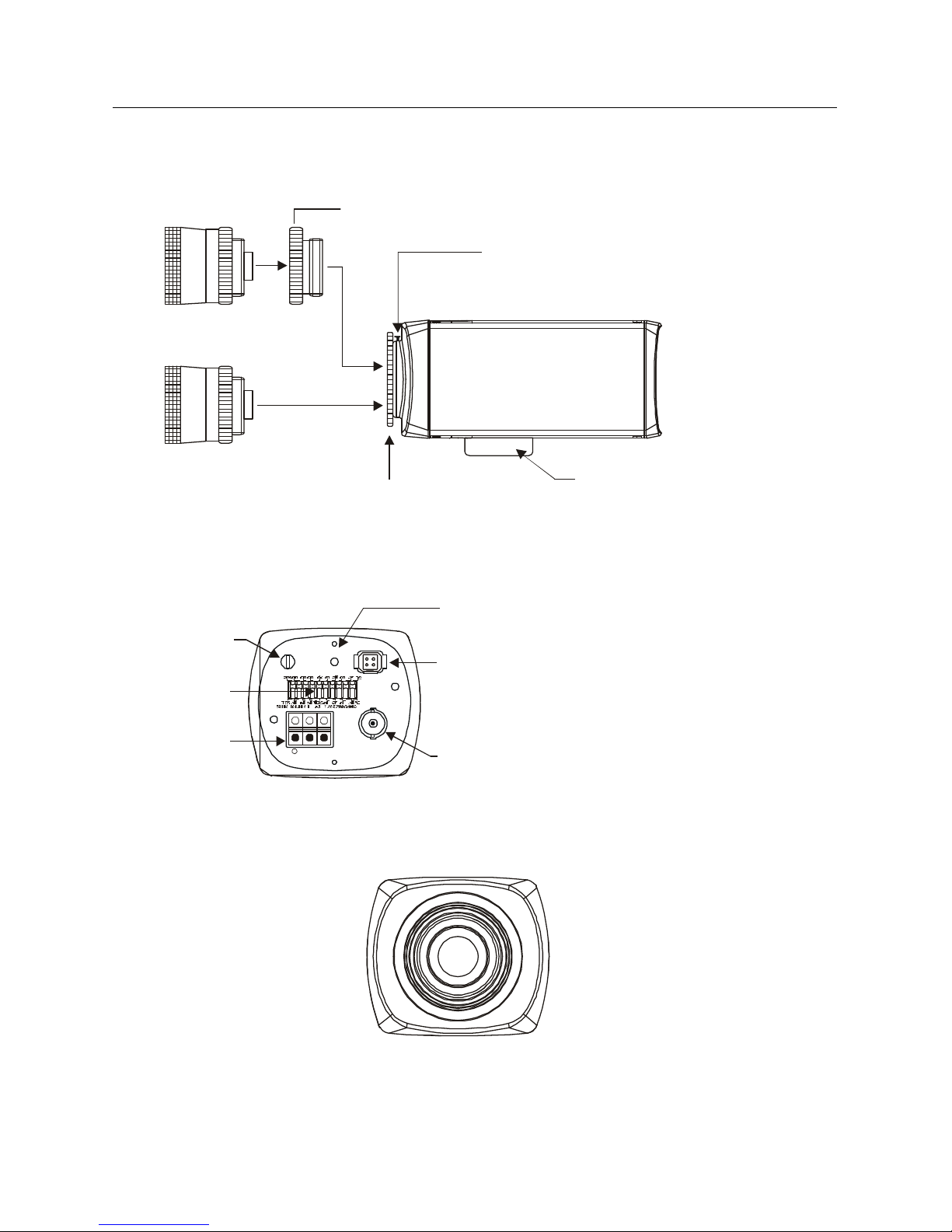
CAMERA OVERVIEW
BACK VIEW (12V DC)
Video Out BNC
Connector
Auto Iris Lens
Connector
FRONT VIEW
SIDE VIEW
C Mount Ring
Back Focus Lock Screw
Back Focus Ring
Camera Mounting Bracket
( C MOUNT LENS )
( CS MOUNT LENS )
Function
Switch
Power LED
Power Input
Terminal
LEVEL PWR
LENS
12V DC
VIDEO OUT
+ GND GND
Level potentiometer
(for DC type A/I lens)

3
1. Back focus Lock Screw – Allows the user to secure the backfocus
setting.
2. C/CS Back focus Adjust Ring – Allows the user to adjust the back focal
length or picture focus by rotating this ring clockwise for C-mount and
counter-clockwise for CS-mount lenses.
3. Mounting Bracket Hole – This threaded ¼"-20 hole is used to mount the
camera onto a mounting bracket or tripod.
4. Iris Adjustment Pot (Potentiometer) – This control allows the user to
adjust the level of the auto iris when the A/I lens selection switch is set to
DC and a DC lens is mounted on the camera. The switch should be in
the video position when an auto iris video lens is mounted on the camera.
If a video auto-iris lens is used, this control has no function.
5. Power LED – This green LED illuminates while power is supplied to the
camera.
6. Auto-iris Lens Connector – This four-pin female connector supplies the
power and either video signal or DC control signal to the auto-iris lens.
7. Function Switches – This compartment houses switches for camera
operation. A switch is in the ON position if it is positioned toward the front
of the camera. If the position is set toward the back of the camera, the
switch is OFF. The switches include:
4
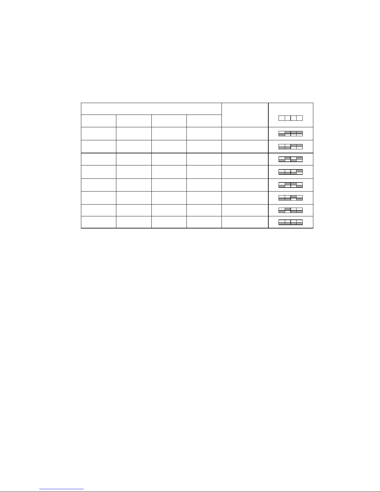
• SHTR Switch (Aes/Mes) – This switch allows the user to choose
between auto exposure and manual exposure. Position the switch
toward the front of the camera for auto exposure, whereby the
exposure is performed by the electronic iris and AGC control. Position
the switch toward the back of the camera for manual exposure,
whereby the shutter speed can be set by the shutter adjust.
*Manual Exposure (SW1= Manual Exposure)
Switch Position
SW1 SW2 SW3 SW4
Shutter Speed
Switch
SW1 2 3 4
MES on on on 1/60(1/50)
MES off on on 1/100(1/120)
MES on off on 1/250
MES off off on 1/500
MES on on off 1/1000
MES off on off 1/2000
MES on off off 1/4000
MES off off off 1/10000
• Flickerless Switch (off/on) – (SW1=Auto Exposure) This function is
used for removing flicker, when camera signal format does not
coincide with power source frequency being used.
• BLC Switch (on/off) – (SW1=Auto Exposure) This on/off switch
controls backlight compensation. When set to ON, the camera will
automatically try to maintain proper exposure in the specific area even
if the lighting level changes.
• E/I (on/off) – (SW1=Auto Exposure)
When set to the ON position, the electronic iris switch automatically
varies the camera’s shutter to mimic auto-iris control, allowing fixed or
manual iris lenses to be used in a wider range. When this switch is set
to ON, turn the F/F switch OFF.
• A/I Switch (dc/video) – The auto iris switch allows the user to select
the supplied auto-iris control signal for the lens. Position the switch
toward the front of the camera to choose DC when the auto-iris control
lens requires DC control signal. Position the switch toward the back of
the camera to choose Video when the auto-iris control lens requires
video signal.
5
• Gamma Switch (on/off) – The gamma correction switch allows .45
correction for non-linearity gain response in the monitor when set to
ON.
When set to OFF, there is no gamma correction.
• AGC Switch (off/on) – The auto gain control switch allows the video
signals to maintain a constant level. This switch is useful when using
the camera at low-light levels and when lighting levels change over
time. For best low light conditions, this switch should set to ON.
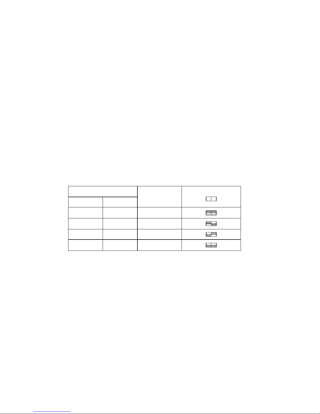
• AWB1, AWB2 Switch (on/off) – This camera have four white balance
setting
ATW (auto tracing white balance) – The camera automatically aim
to maintain white objects as white even if the light color changes.
AWB (auto white balance) – Quick ATW.
Indoor – improves the color balance in areas where a mixture of light
sources exist.
Outdoor – Improves the color balance in arrears where day light is
the main source of light.
Switch Position
SW8 SW9
Mode
Switch
SW8 9
on on ATW
on off AWB
off on Indoor
off off Outdoor
8. Power Input Terminal – This terminal accepts a 12V DC power source
from a 12V DC +/- 20% using a UL-listed Class 2 power supply only.
9. Video Out BNC Connector – This BNC connector provides a 1.0 Vpp/75 Ohms composite video signal.

6
CONTENTS OF PACKAGE
Installation of the camera must be performed by qualified service personnel in
accordance with all local and national electrical and mechanical codes.
Carefully remove the color camera and its accessories from the carton and
verify that they were not damaged in shipment.
The contents of the package includes:
1. Color CCD camera
2. Mini-DIN connector (for video- or dc-type auto-iris lens)
BASIC INSTALLATION
After unpacking and identifying the package contents, perform the following
steps to connect the camera to an observation system.
1. Locate the following items, which may be needed during installation but
are NOT supplied with the camera:
• Camera lens
• Video cable
• Camera stand or mounting bracket
• 12V DC power supply
• Mounting hardware
• Observation monitor
• Welder’s glass
• Tools
2. Select a suitable location for the camera.
IMPORTANT: Contact your authorized Ultrak
dealer/distributor to purchase cable which is available in
various lengths according to the application.
3. Use a suitable fastener and necessary tools to mount the camera stand
or mounting bracket to a structural object, such as a wall stud or ceiling
rafter, that can support the weight of the camera and mount.
7
IMPORTANT: The minimum recommended load rating for
the mounting bracket is 11 lbs (5Kg).
4. The observation camera has a ¼"-20 UNC mounting holes located at the
top and the bottom of the camera housing to allow for top or bottom
mounting. Mount the camera on the stand by threading the mounting bolt
into either mounting hole on the camera.
IMPORTANT: Do not aim or point the camera towards the
sun or into a strong light.
5. Install the lens. If a C- or CS-mount lens is used, adjust the back focal
length or picture focus.
• For C-mount lenses, rotate the focus adjust ring clockwise.
• For CS-mount lenses, rotate the focus adjust ring counterclockwise.
6. If an auto-iris lens is used, connect the cable of the lens to the mini-DIN
connector supplied with the camera. Insert the lens connector into the
auto-iris connector on the camera.
7. Route the assembled cable from the monitor location to the camera
location.
WARNING: Care should be taken when routing the cable
from the monitor to the camera. Try not to put
unnecessary strain on the cable or connectors. Do not
place the cable next to fluorescent lights as interference
may result. Do not use staples to support the cable as they
may damage the cable. If the provided camera cable is not
long enough, do not substitute a telephone cable as it
could damage the camera and/or the monitor. Contact
your authorized Ultrak dealer/ distributor to purchase
longer cables.
8. Plug the cable into the BNC output port labeled VIDEO OUT located on
the back of the camera.

8
9. Plug the other end of the cable into the corresponding camera input port
on the back of the observation monitor.
On 12V DC models :
10. Connect a 2-conductor power cable to the 12V DC input port located on
the back of the camera.
Use a UL-listed Class 2 power
transformer and a 12V DC power
adapter. Use only a Class 2 power
source.
11. Apply 12V DC power to the camera.
12V DC Class 2
GND GND
+

9
MANUAL IRIS LENS ADJUSTMENT
A manual iris lens is used in indoor applications where lighting from windows
can considerably affect the light level of the room. When using the manual
iris lens, perform the following:
1. Set the E/I switch to ON.
2. Turn the iris ring on the lens to the fully OPEN position.
3. Focus the lens to obtain optimum picture.
4. To increase the camera’s depth of field, slightly close the manual iris by
approximately five to ten percent.
VIDEO-TYPE AUTO-IRIS LENS INSTALLATION
AND ADJUSTMENT
The cameras support video-type auto-iris lenses to adjust for changing light
levels. Perform the following steps to install and adjust a video-type auto-iris
lens.
1. Thread the video-type auto-iris lens onto the lens mount on the front of
the camera.
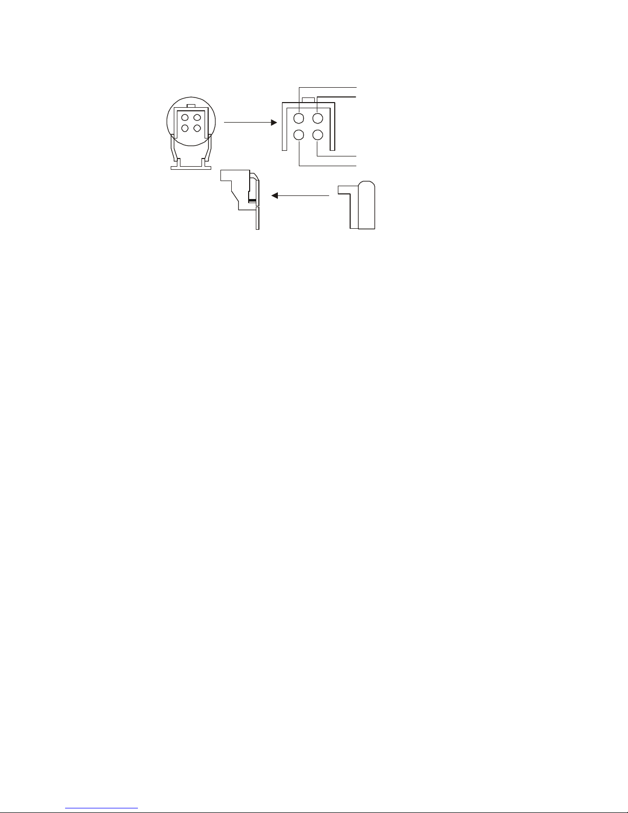
2. If necessary, solder the lens control wires to the connector supplied with
the camera.
Use the following pin-out and wire color-coding chart as a guide:
PIN NAME WIRE COLOR
1 Voltage + Red
2 Open -3 Video White
4 Ground Black
10
3. Plug the connector into the auto-iris lens jack on the top of the camera.
The connector is keyed and can only be inserted into the jack one way.
4. Make sure that the E/I switch located on the back of the camera is set to
OFF and the A/I switch is set to Video.
5. Apply power to the camera.
6. Adjust the focus ring on the lens for an optimum picture. If the picture is
not visible, set the lens for proper exposure by adjusting the ALC
(automatic level control) and level on the lens. The ALC setting can
range between AVG (average) or PK (peak).
An AVG setting is appropriate for most applications.
For ALC adjustments:
AVG
To slow the reaction of the lens to changing light, set the
range on the AVG setting to average the video level
from the camera. Use this when there are bright spots in
the picture, such as lights or glare from the sun.
PK
To increase the speed of the lens reaction to the
changing light, set the lens adjustment to PK so the lens
will adjust to the brightest or peak object in the video.
Use this setting if you want to see the brightest object
and not the background objects.
For Level adjustments:
Adjust the Level control for the best picture during the day. A night
adjustment may not provide the proper setting for controlling the light
during the day.
Open
Voltage + / Red
Video / White
Ground / Black
1
4
2
3

11
7. Set the backfocus of the camera before the final adjustment of the video
level. See section 3.6 for further instructions.
8. If the auto-iris has a gain adjustment:
• If the lens oscillates between open and closed under bright lights,
slowly turn the gain adjustment counter-clockwise until the
oscillating stops.
• Increase the light getting to the camera by adjusting the level control
and readjusting the gain control as necessary.
DC-TYPE AUTO-IRIS LENS INSTALLATION
AND ADJUSTMENT
The cameras support DC-type auto-iris lenses.
Perform the following steps to install and adjust a DC-type auto-iris lens.
1. Thread the DC-type auto-iris lens onto the lens mount on the front of the
camera.
2. If using an Ultrak lens, skip to step 3.
If using a non-Ultrak lens, use the manufacturer’s instructions to solder
the connector that comes supplied with the camera to the lens control
wires. The pin-out and wire color-coding for DC-type
auto-iris lenses can vary from one manufacturer to another.
3. Plug the connector into the dc iris jack on top of the camera. The
connector is keyed and can only be inserted into the jack one way.
4. Make sure that the E/I switch located on the back of the camera is set to
OFF and the A/I switch is in the DC position.
5. Apply power to the camera.
6. Adjust the DC-type auto-iris lens for an optimum picture using the IRIS
LEVEL control on the back of the camera.

12
BACKFOCUS ADJUSTMENT
Although the camera lens was backfocused by the manufacturer prior to
shipping, it may be necessary to make modifications.
For best results, perform backfocus adjustments at night or while using a #6
or #8 welder’s glass in front of the lens. The focus of the camera will change
slightly if the camera iris was adjusted on a light scene and then changes to a
dark scene. However, the camera will remain in focus if the iris was focused
on a dark scene and the scene lightens.
To make backfocus adjustments, perform the following:
1. After mounting the lens on the camera, apply power.
2. If a picture is visible, focus on the scene. If a picture is not visible, open
the iris on the lens. Open the lens as wide as possible by placing a
welder’s glass in front of the lens.
3. When the iris is open to the widest point, readjust the focus for a clear
picture. If a clear picture is not visible, set the focus ring to midrange.
4. Loosen the backfocus lock screw.
5. Adjust the backfocus ring for a clear picture.
6. Tighten the backfocus lock screw.
7. Fine-tune the focus with the focus ring on the lens.
8. Remove the welder’s glass from the front of the lens.
9. Adjust the iris of the lens for the best picture quality.

13
ZOOM LENS BACKFOCUS ADJUSTMENT
The objective of backfocusing a zoom lens is similar to that of a fixed focal
length camera, except that the backfocus is also adjusted to maintain the
focus when “zooming” the lens in and out of a scene.
For zoom lens backfocus adjustment, perform the following:
1. Choose an object at the farthest range that you wish to look at with a
zoom lens.
2. Make sure that the iris of the lens is wide open.
For best results, make the adjustment by using a
#6 or #8 welder’s glass placed in front of the lens.
3. Adjust the focus on the lens to the far range.
4. Adjust the zoom on the lens to obtain the widest picture.
5. Loosen the backfocus lock screw.
6. Adjust the focus adjust ring for the clearest picture.
7. Adjust the zoom on the lens to the far telephoto position.
8. Adjust the backfocus ring for the clearest picture.
9. Adjust the zoom on the lens back to the widest picture.
10. Readjust the backfocus for the clearest picture.
11. Tighten the backfocus lock screw.
IMPORTANT: Verify that the camera remains in focus after
tightening the lock screw. On occasion, tightening the lock
screw can cause the camera to be slightly out of focus.
12. Repeat the previous steps as many times as necessary to maintain a
clear picture through the entire zoom range.

14
TROUBLESHOOTING
If problems occur, verify the installation of the camera with the instructions in
this manual and with other operating equipment. Isolate the problem to the
specific piece of equipment in the system and refer to the equipment manual
for further information.
PROBLEM CHECK
NO POWER
Make sure the system is plugged in.
Make sure the main power switch on the back
of the observation monitor is in the ON
position.
Check the outlet for power.
POWER, BUT NO PICTURE
Verify power to all pieces of equipment in the
system (camera green LED on)
Verify that the video cables are connected
correctly.
Verify that the lens cap has been removed
from the lens or that the iris of the lens is
open.
VIDEO, BUT NO CONTROL
Power down the system for one minute, then
turn power back ON.
DARK VIDEO
Adjust iris. Check A/I connections.

15
PREVENTIVE MAINTENANCE
Following the preventive maintenance schedule allows detection and
correction of minor faults before they become serious and cause equipment
failure.
Every three months, perform the following:
A. Inspect all connecting cables for deterioration or other damage.
B. Clean components with a clean damp cloth.
C. Verify that all mounting hardware is secure.

16
SPECIFICATIONS
* Standard Resolution DSP Color Camera *
Power
Power Source, Consumption : 12VDC +/-20%
Max. 5.0 Watts.
Power Indicator : Green LED
Sensor Information and General
Processing Technology : Sony DSP
Image Sensor : 1/3" interline transfer CCD (sony chip
set)
Picture Element : 537(H) x 505(V), NTSC
537(H) x 597(V), PAL
Chip Size : 6.0mm(H) x 4.96mm(V)
Unit Cell Size : 9.6µm(H) x 7.5µm (V), NTSC 9.8µm(H)
x 6.3µm (V), PAL
Scanning System : 2:1 Interlace
Scanning Frequency : 15.75KHz(H) x 60Hz(V), NTSC
15.625KHz(H) x 50Hz(V), PAL
Sync System : Internal
Electronic Shutter : 1/60(1/50) ~ 1/100000 sec.
Operating Temperature / Humidity : 14°F to 122°F (-10°C to +50°C) /
<96% (non-condensing)
Video
Signal Format : NTSC, 525 Lines
PAL, 625 Lines
Resolution : 330TV Lines
Minimum Illumination: 1.0 Lux (F1.4)
Video Output: 1.0 Vp-p, 75 Ohms, unbalanced
Video Iris Output: 650mV at video out 1.0 Vp-p
S/N Ratio : 50dB(AGC Off)
BLC Size : 40% Center
Sync Level : 40 IRE, PAL 300mV
White Clip : 120 IRE, PAL 850mV

17
Function
Auto/Man Shutter Control(E.S.) : Auto(On), Man(Off) (Dip Switch)
Manual Shutter Control : 1/60(1/50), 1/100(1/120), 1/250, 1/500,
1/1000, 1/2000, 1/4000, 1/10,000(Dip
Switch)
Flickerless(F.F) : ON/OFF (Dip Switch)
BLC : ON/OFF (Dip Switch)
EI : ON/OFF (Dip Switch)
Auto Iris Lens : DC/Video (Dip Switch)
Gamma(γ) : ON/OFF (Dip Switch)
AGC : ON/OFF (Dip Switch)
White Balance : ON/OFF (Dip Switch)
Auto, Quick, Indoor, Outdoor
DC Iris Level Adjust : Adjustable (POT)
Connector and Mechanical
Video Output : BNC Connector
Power Input : 3-pin Terminal Block or Power Cord
AI/DC Output : 4-pin mini din jack (Standard
Connection)
Lens Mount : C/CS (Selected through back focus)
Mounting Hole : 1/4" UNC Top and Bottom
External Dimensions : 2.44W x 2.1H x 5.0D inch
(62W x 54H x 127D mm)
Weight : 235g at 12V DC model

18
* High Resolution DSP Color Camera *
Power
Power Source, Consumption : 12VDC +/-20%
Max. 5.0 Watts.
Power Indicator : Green LED
Sensor Information and General
Processing Technology : Sony DSP
Image Sensor : 1/3" interline transfer CCD
(sony chip set)
Picture Element : 811(H) x 508(V), NTSC
795(H) x 596(V), PAL
Chip Size : 6.0mm(H) x 4.96mm(V)
Unit Cell Size : 6.35µm(H) x 7.4µm (V), NTSC
6.5µm(H) x 6.25µm (V), PAL
Scanning System : 2:1 Interlace
Scanning Frequency : 15.75KHz(H) x 60Hz(V), NTSC
15.625KHz(H) x 50Hz(V), PAL
Sync System : Internal
Electronic Shutter : 1/60(1/50) ~ 1/100,000 sec.
Operating Temperature / Humidity : 14°F to 122°F (-10°C to +50°C) /
<96% (non-condensing)
Video
Signal Format : NTSC, 525 Lines
PAL, 625 Lines
Resolution : 470 TV Lines
Minimum Illumination: 1.0 Lux (F1.4)
Video Output: 1.0 Vp-p, 75 Ohms, unbalanced
Video Iris Output: 650mV at video out 1.0 Vp-p
S/N Ratio : 50dB(AGC Off)
BLC Size : 40% Center
Sync Level : 40 IRE, PAL 300mV
White Clip : 120 IRE, PAL 850mV

19
Function
Auto/Man Shutter Control(E.S.) : Auto(On), Man(Off) (Dip Switch)
Manual Shutter Control : 1/60(1/50), 1/100(1/120), 1/250, 1/500,
1/1000, 1/2000, 1/4000, 1/10,000(Dip
Switch)
Flickerless(F.F) : ON/OFF (Dip Switch)
BLC : ON/OFF (Dip Switch)
EI : ON/OFF (Dip Switch)
Auto Iris Lens : DC/Video (Dip Switch)
Gamma(γ) : ON/OFF (Dip Switch)
AGC : ON/OFF (Dip Switch)
White Balance : ON/OFF (Dip Switch)
Auto, Quick, Indoor, Outdoor
DC Iris Level Adjust : Adjustable (POT)
Connector and Mechanical
Video Output : BNC Connector
Power Input : 3-pin Terminal Block or Power Cord
AI/DC Output : 4-pin mini din jack (Standard Connection)
Lens Mount : C/CS (Selected through back focus)
Mounting Hole : 1/4" UNC Top and Bottom
External Dimensions : 2.4W x 2.1H x 5.0D inch
(62W x 54H x 127D mm)
Weight : 235g at 12V DC model

20
DSP COLOR CAMERA
1/3” INTERLINE TRANSFER CCD
STANDARD RESOLUTION
HIGH RESOLUTION 50301421A
 Loading...