


8CH FX-TRON
Instruction Manual
Please read this manual thoroughly before use and keep it handy for future reference
Rev. 110308

WARNING AND CAUTION
WARNING
TO REDUCE THE RISK OF FIRE OR ELECTRIC SHOCK, DO NOT EXPOSE THIS
PRODUCT TO RAIN OR MOISTURE. DO NOT INSERT ANY METALLIC OBJECTS
THROUGH THE VENTILATION GRILLS OR OTHER OPENINGS ON THE
EQUIPMENT.
CAUTION:
EXPLANATION OF GRAPHICAL SYMBOLS

F
FCC COMPLIANCE
FCC INFORMATION: THIS EQUIPMENT HAS BEEN TESTED AND FOUND TO COMPLY
WITH THE LIMITS FOR A CLASS A DIGITAL DEVICE, PURSUANT TO PART 15 OF THE
FCC RULES. THESE LIMITS ARE DESIGNED TO PROVIDE REASONABLE
PROTECTION AGAINST HARMFUL INTERFERENCE WHEN THE EQUIPMENT IS
OPERATED IN A COMMERCIAL ENVIRONMENT. THIS EQUIPMENT GENERATES,
USES, AND CAN RADIATE RADIO FREQUENCY ENERGY AND IF NOT INSTALLED
AND USED IN ACCORDANCE WITH THE INSTRUCTION MANUAL, MAY CAUSE
HARMFUL INTERFERENCE TO RADIO COMMUNICATIONS. OPERATION OF THIS
EQUIPMENT IN A RESIDENTIAL AREA IS LIKELY TO CAUSE HARMFUL
INTERFERENCE IN WHICH CASE THE USER WILL BE REQUIRED TO CORRECT THE
INTERFERENCE AT HIS OWN EXPENSE.
CAUTION: CHANGES OR MODIFICATIONS NOT EXPRESSLY APPROVED BY THE
PARTY RESPONSIBLE FOR COMPLIANCE COULD VOID THE USER'S AUTHORITY TO
OPERATE THE EQUIPMENT.
THIS CLASS A DIGITAL APPARATUS COMPLIES WITH CANADIAN ICES-003.
CET APPAREIL NUMÉRIQUE DE LA CLASSE A EST CONFORME À LA NORME NMB-
003 DU CANADA.
CE COMPLIANCE STATEMENT
WARNING
THIS IS A CLASS A PRODUCT. IN A DOMESTIC ENVIRONMENT THIS PRODUCT MAY
CAUSE RADIO INTERFERENCE IN WHICH CASE THE USER MAY BE REQUIRED TO
TAKE ADEQUATE MEASURES.

IMPORTANT SAFETY INSTRUCTIONS
1. Read these instructions.
2. Keep these instructions.
3. Heed all warnings.
4. Follow all instructions.
5. Do not use this apparatus near water.
6. Clean only with dry cloth.
7. Do not block any ventilation openings. Install in accordance with the manufacturer’s instructions.
8. Do not install near any heat sources such as radiators, heat registers, stoves, or other
apparatus (including amplifiers) that produce heat.
9. Do not defeat the safety purpose of the polarized or grounding-type plug. A polarized plug has
two blades with one wider than the other. A grounding type plug has two blades and a third
grounding prong. The wide blade or the third prong are provided for your safety. If the provided
plug does not fit into your outlet, consult an electrician for replacement of the obsolete outlet.
10. Protect the power cord from being walked on or pinched particularly at plugs, convenience
receptacles, and the point where they exit from the apparatus.
11. Only use attachments/accessories specified by the manufacturer.
12. Use only with the cart, stand, tripod, bracket, or table specified by the
manufacturer, or sold with the apparatus. When a cart is used, use caution
when moving the cart/apparatus combination to avoid injury from tip-over.
13. Unplug this apparatus during lightning storms or when unused for long
periods of time.
14. Refer all servicing to qualified service personnel. Servicing is required when
the apparatus has been damaged in any way, such as power-supply cord or
plug is damaged, liquid has been moisture, does not operate normally, or has been dropped.
1
15. CAUTION – THESE SERVICING INSTRUCTIONS ARE FOR USE BY QUALIFIED
SERVICE PERSONNEL ONLY. TO REDUCE
THE RISK OF ELECTRIC SHOCK
DO NOT PERFORM ANY SERVICING OTHER THAN THAT CONTAINED IN THE
OPERATING I
NSTRUCTIONS UNLESS YOU QRE QUALIFIED TO DO SO.
16. Use Certified/Listed Class 2 power source only.
17.
Apparatus shall not be exposed to dripping or splashing and no object filled with liquids,
such as vases, shall be placed on the apparatus.

Table of Contents
CHAPTER 1 — INTRODUCTION .............................................................................................. 6
1.1 Features ........................................................................................................................................ 6
1.2 System Configuration .................................................................................................................... 6
1.2.1 Front & Rear .............................................................................................................................. 6
1.2.2 Dip switch Configu ra tio n s & Settings ......................................................................................... 7
C H A P T E R 2 — I N S T A L L A T I O N ................................................................................................ 9
2.1 System Connection and Operation ............................................................................................... 9
2.2 Camera Configuration with Keyboard ......................................................................................... 10
CHAPTER 3 — SPECIFICATION ............................................................................................ 11
3.1 Equipment Spe c ifica tio n ............................................................................................................. 11
3.2 Signal Strengths by Video Cable Types ..................................................................................... 11
3.3 Dimensions ................................................................................................................................. 12
3.4 Package Contents ....................................................................................................................... 12

6
Chapter 1 — Introduction
1.1 Features
The 8 channel FX-Tron box is a device that converts RS485 serial data from keyboard to coaxial data
on video signal of camera so that can control PTZ cameras without serial communication cable
Activated channel LED-display
8 channel video Input(camera), output(monitor)
Up to 32 FX-Tron devices, up to 256 cameras configurable
RS485 serial communication with keyboard controller
5 baudrate supported: 2400, 4800, 9600, 19200, 38400 bps
4 protocol supported to each channel independently: Fastrax2, Fastrax2E, Pelco P, Pelco D
12VDC power
19inch rack mount
1.2 System Configuration
1.2.1 Front & Rear
Figure 1. Front & Rear
<Front>
- POWER : Power LED
- CH1~8 : Activated channel display LED
<Rear>
- CAM : Camera BNC input, CH1~8
- MON : Monitor BNC output, CH1~8
- RS485 SETUP : 4 pin dip switch setup, RS485 baudrate and answer enable
- SYSTEM SETUP : 8 pin dip switch setup, FX-Tron ID, Video mode and RS485 termination
* Refer to chapter 1.2.2 to setup dip switch
- RS485 : Keyboard communication port
- DC jack : DC12V power

7
1.2.2 Dip switch Configurations & Settings
● RS485 SETUP (Baudrate and Answer enable)
Table 1. RS485 Baudrate
BAUDRATE
Dip Switch
1 2 3
2400 bps
OFF OFF OFF
4800 bps
OFF OFF ON
9600 bps
OFF ON OFF
19200 bps
OFF ON ON
38400 bps
ON OFF OFF
The baudrate on the FX-Tron box must correspond to that of the keyboard controller for proper
communication. Setup baudrate refer to Table 1. Default setting is 9600bps.
Table 2. RS485 answer enable
Dip Switch OFF ON
4 ANSWER No alarm answer Receive alarm answer
Set the switch to ON to receive alarm answer from FX-Tron box. Only Fastrax2 and Fastrax2E
protocol support answer. Default setting is ON.

8
● SYSTEM SETUP (FX-Tron ID, Video mode, RS485 termination)
Table 3. FX-Tron ID setup
ID
Dip Switch
ID
Dip Switch
1 2 3 4 5 1 2 3 4 5
1
OFF OFF OFF OFF OFF
17
ON OFF OFF OFF OFF
2
OFF OFF OFF OFF ON
18
ON OFF OFF OFF ON
3
OFF OFF OFF ON OFF
19
ON OFF OFF ON OFF
4
OFF OFF OFF ON ON
20
ON OFF OFF ON ON
5
OFF OFF ON OFF OFF
21
ON OFF ON OFF OFF
6
OFF OFF ON OFF ON
22
ON OFF ON OFF ON
7
OFF OFF ON ON OFF
23
ON OFF ON ON OFF
8
OFF OFF ON ON ON
24
ON OFF ON ON ON
9
OFF ON OFF OFF OFF
25
ON ON OFF OFF OFF
10
OFF ON OFF OFF ON
26
ON ON OFF OFF ON
11
OFF ON OFF ON OFF
27
ON ON OFF ON OFF
12
OFF ON OFF ON ON
28
ON ON OFF ON ON
13
OFF ON ON OFF OFF
29
ON ON ON OFF OFF
14
OFF ON ON OFF ON
30
ON ON ON OFF ON
15
OFF ON ON ON OFF
31
ON ON ON ON OFF
16
OFF ON ON ON ON
32
ON ON ON ON ON
Table 4. Camera ID definition
FX-Tron ID
Camera ID
CH1 CH2 CH3 CH4 CH5 CH6 CH7 CH8
1 1 2 3 4 5 6 7 8
2 9 10 11 12 13 14 15 16
3 17 18 19 20 21 22 23 24
4 25 26 27 28 29 30 31 32
5 33 34 35 36 37 35 39 40
.
.
.
.
.
.
.
.
.
.
.
.
.
.
.
.
.
.
31 241 242 243 244 245 246 247 248
32 249 250 251 252 253 254 255 256
Note) ID of ‘PELCO’ protocol camera is based on ‘P-address. For example if D-address is ‘1’
and P-address is ‘2’, the camera ID is ‘2’.
Table 5. Video mode and RS485 port termination
Dip Switch OFF ON
6 N/P (NTSC/PAL) Video mode NTSC Video mode PAL
8 TERMINATION Not terminated Terminated
The first and the last devices in an system installation(RS485 cascade connection) must have the
data line terminated by setting the dip switch 8. Without proper termination, there is potential for
control signal errors. Total length of the cable for communication should not exceed 4000ft (1.2Km).
Note) Dip switch 7 is no use, keep the switch to OFF.

9
Chapter 2 — Installation
2.1 System Connection and Operation
Figure 2. Transmission Diagram
- To control PTZ camera with FX-Tron, connect system as below.
1. Setup Fx-Torn ID(camera ID), video mode(NTSC/PAL) and RS485 port termination with dip switch.
2. Configure camera ID, protocol and port to keyboard.
If camera protocol is F2 or F2E, it is not necessary to configure ‘CAMERA’ of keyboard. Configure
Pelco protocol camera refer to chapter 2.2.
3. Connect keyboard RS485 port and FX-Tron RS485 port.
4. Connect camera video output to CAM of FX-Tron box.
5. Connect MON of FX-Tron to monitor.
6. Select camera (ID + CAM key), and control PTZ camera with keyboard.
7. FX-Tron box’s front led displays current selected camera channel.
Note) Turn FX-Tron power off before setting dip switches.
Note) Run camera scan function with keyboard after connecting cameras for stable global
function like global preset.

10
2.2 Camera Configuration with Keyboard
The keyboard detects Fastrax4 dome camera automatically via scan function. But it is necessary to
configure Pelco protocol camera to camera menu in the keyboard for controlling PTZ with FX-Tron.
Configure Pelco camera information to the keyboard as below.
< HKBD01 Camera Setup >
Press ‘CTRL’ and ‘MENU’ key simultaneously and enter keyboard CAMERA setup menu. This
camera setup is listed up to 64 cameras and the camera ID has up to 256.
Cam : Camera ID
PR : Protocol[F2,F2E,P-D(PELCO-D),P-P(PELCO-P)]
PT : Port[D1(DOME1),D2(DOME2)]
BR : Baudrate
This camera setup is listed up to 64 cameras and the camera ID has up to 256.
When the keyboard has that the Alarm Check option is ON, the camera setup is set automatically
after the keyboard checks the camera at the first power on or after the scan dome function.
At this time, the F2E protocol could not be changed.
To add the other camera:
1. Select the blank line (- - -) by moving the joystick down or up.
2. Twist the handle of the joystick clockwise, then the next camera number displays or press camera
number and CAM key, if that number is not already defined, the camera number displays.
3. Set the appropriate protocol and port moving the cursor (←)by the joystick.
Alarm check option is ON: P-D (PELCO-D), P-P (PELCO-P)
Alarm check option is OFF: F2, F2E, P-D (PELCO-D), P-P (PELCO-P)
4. Set the appropriate baudrate of the camera(FX-Tron).
5. Repeat step 1-4 to add a new camera.
6. Press CTRL to save and exit. Press OFF to delete the saved camera. Press the ESC key to exit
without saving.
7. To change the camera, repeat step 2-6 after selecting the desired camera number.
When the keyboard has that the alarm check option is OFF, the camera setup displays the blank
value after the first power on. At this time, set all cameras according to the procedure above.
Refer to Keyboard manual for detail setup.
Cam<- PR PT BR
0001 P-D D1 9600

11
Chapter 3 — Specification
3.1 Equipment Specification
GENERAL
Regulatory Conformity
FCC, CE, RoHS
ELECTRICAL
Input Voltage 12 VDC
Power Consumption 3W
Communication
RS-485
BNC Video Input Connection camera video port(1Vp-p 75 Ohm unbalanced)
BNC Video Output To Monitor BNC port(1Vp-p 75 Ohm unbalanced)
MECHANICAL 5
Dimension
13.79x4.75x1.73 (Unit : inch) / 350x120.5x44 (Unit : mm)
Unit Weight Approx. 44.80 (Unit : oz) / 1.27 (Unit : kg)
Shipping Weight Approx. 75.14 (Unit : oz) / 2.13 (Unit : kg)
Shipping Size 19.88 x 8.46 x 6.69 (Unit : inch) / 505 x 215 x 170 (Unit : mm)
ENVIRONMENT
Operation Temperature
0°C to 35°C (32°F to 95°F)
Operating humidity 10% to 90%RH (non-condensing)
Storage temperature
-20°C to 60°C ( -4°F to 140°F)
Specifications are subject to change without notice.
3.2 Signal Strengths by Video Cable Types
Refer to the chart below for the minimum cable requirements and the maximum cable distance
by cable types.
● Minimum Cable Requirements
- 75 ohms impedance
- All copper center conductor
- All copper braided shield with 95% braid coverage
Cable Types Maximum Distance
RG59/U 750 ft(228m)
RG6/U 1000 ft(304m)
12
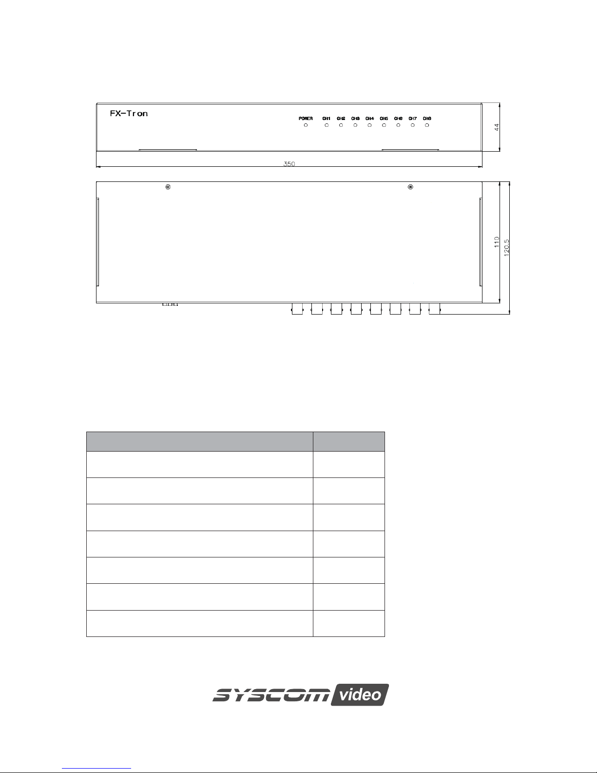
3.3 Dimensions
Figure 3. Dimension
3.4 Package Contents
The package contains the following.
DESCRIPTION Q’ty
FX tron Box 1
Instruction manual 1
12VDC Power supply 1
19inch rack mount 2
Machine Screw FC2x6 10
Machine Screw M5x10 4
Rubber Foot 4
 Loading...