

SYRUNS SY6000-Z, SY6000-Z01140Y, SY6000-Z02240Y, SY6000-Z03040Y, SY6000-Z01540Y Series Manual
...Page 1

Contents
PREFACE...............................................................................................1
CHAPTER 1 PRINCIPLE OF ENERGY SAVING...............................2
CHAPTER 2 FEATURES ......................................................................4
2.2 INSTRUCTION OF MODEL NO. ............................................................4
2.3 SPECIFICATIONS ................................................................................4
2.4 OVERALL DIMENSIONS......................................................................5
CHAPTER 3 INSTALLATION..............................................................6
3.1 INSTALLATION SITE...........................................................................6
3.2 PRECAUTIONS:..................................................................................6
3.3 MAIN CIRCUIT AND CONTROL CIRCUIT .............................................7
CHAPTER 4 OPERATION....................................................................8
4.1 SWITCHOVER BETWEEN POWER FREQUENCY AND ENERGY-SAVING .8
4.1.1 Running at energy-saving switching to power frequency......8
4.1.2 Running at power frequency switching to energy saving......8
4.2 TESTING STAGE OF THE CABINET......................................................9
4.3 NORMAL USING STAGE......................................................................9
4.4 KEYPAD OPERATION .................................................................10
4.4.1 KEYPAD FUNCTION ......................................................................10
4.4.2 KEYPAD BASIC OPERATION ..........................................................10
4.4.2.1 Direct display status..........................................................10
4.4.2.2 Switchover of display parameter.......................................10
CHAPTER 5 PARAMETERS..............................................................12
CHAPTER 6 TROUBLESHOOTING.................................................18
6.1 FAULT CODE AND REASON ANALYSIS ..............................................18
6.2 ADJUSTMENT OF DEFECTIONS.........................................................20
CHAPTER 7 MAINTENANCE...........................................................22
7.1 DAILY INSPECTION..........................................................................22
7.2 REGULAR MAINTENANCE................................................................22
7.3 PERIODIC MAINTENANCE................................................................23
7.4 STORAGE.........................................................................................23
0
Page 2

User Manual of SY6000-Z series Preface
PREFACE
Thanks for choosing SY6000-Z series moulding injection
energy saving cabinet.
SY6000-Z series cabinet is high quality moulding injection
energy saving drive which is designed according to
IEC618000/IEC610000. The cabinet owns protection functions of
phase-loss, over voltage, under voltage, over current, etc.
SY6000-Z series cabinet is suitable for kinds of moulding
injection machine with hydraulic control proportional pump. It
controls output power of motor according to pressure signal and
flow signal of moulding injection machine to reach the objective
of energy saving. The energy saving rate may get 25%~65%.
SY6000-Z series cabinet can work for pump motors which
power ratings are from 11KW~55KW. It also can apply for one
moulding injection machine with multiple pump motors.
Before using SY6000-Z series cabinet, in order to keep
people in safe and acquire better energy-saving effect, please read
the manual thoroughly. If you meet with tough problems when
using, please contact us in time.
Please retain this manual and you will use it if necessary in
future.
1
Page 3

User Manual of SY6000-Z series Principle of energy-saving
Chapter 1 Principle of energy saving
Power consumption of moulding injection machine
mainly in the following sections:
① Power consumption of hydraulic pump system;
② Power consumption of heaters;
③ Power consumption of circulating cooling water pump
Electricity consumption of hydraulic pump accounts for
80% energy consumption of the injection molding machine, so
reducing the power consumption is the key to save energy for
molding injection machine.
The pressure and flow are changing when molding
injection machine is in matching mould, cross locking,
injection, material storing, cooling and other stages.
When oil need of the injection molding machine changes,
the relief valve in pump outlet will adjust pressure and flow of
the load, while the output motor power is the same, thus results
in waste of energy.
According to requirements of pressure and speed at the
current work status of moulding injection machine, such as
stages of mold, lock cross, shooting rubber, material storage
and cooling, SY6000-Z series cabinet can adjust automatically
the pump speed the fuel supply to make actual fuel supply be
consistent with actual load flow at any working stage.
Thus it eliminates overflowing of hydraulic oil, reduces
pump output, and saves electricity consumption of pump motor,
so as to achieve the best energy-saving state of moulding
injection machine.
2
Page 4

User Manual of SY6000-Z series Principle of energy-saving
3
Page 5
User Manual of SY6000-Z series Features
Chapter 2 Features
2.1 SY6000-Z series cabinet is suitable for quantitative pump
moulding injection machine. Its features are as follows:
z Adopt advanced space voltage vector PWM control algorithm, with
advanced technology and low output current harmonic content, without
power supply pollution
z With timing functions, cumulative working time can be recorded
under energy saving state.
z Adopt high-quality imported components, product quality assured
z Excellent fault management and protection features make cabinet and
motor away from damage under no circumstance
z Large capacity of instantaneous impact current, up to 250%; overload
capacity 180% per minute
z No trip when the moulding injection machine is under high pressure
plastic injection and heavy load, so as do not affect production, ensure
product quality
z Advanced integrated cabinet, with switchover of power frequency /
energy saving, with dedicated air channel, compact structure, easy to
install
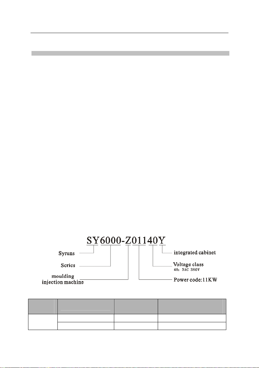
2.2 Instruction of model no.
2.3 Specifications
Voltage
class
380V
Model no.
SY6000-Z01140Y 11.0 24 3PH
SY6000-Z01540Y 15.0 33
Power rating
(kW)
4
Rated output current
(A)
Page 6
User Manual of SY6000-Z series Features
Voltage
class
Model no.
Power rating Rated output current
(kW) (A)
SY6000-Z01840Y 18.5 39
SY6000-Z02240Y 22.0 44
SY6000-Z03040Y 30.0 60
SY6000-Z03740Y 37.0 75
SY6000-Z04540Y 45.0 90
SY6000-Z05540Y 55.0 110
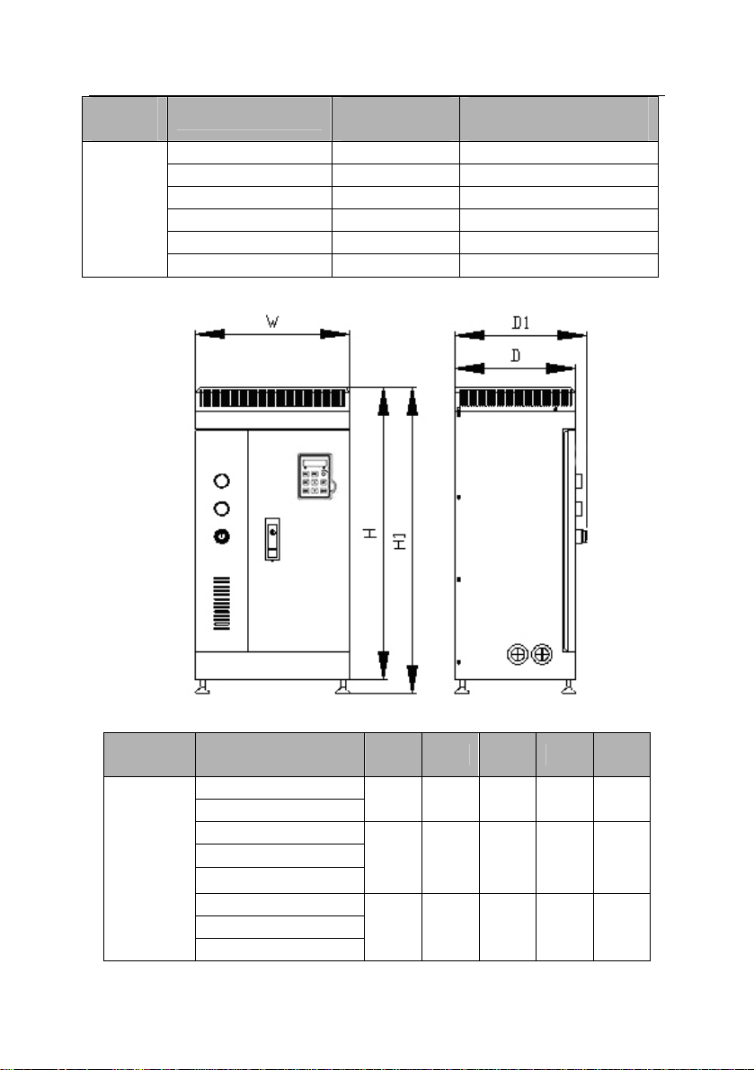
2.4 Overall dimensions
Installation dimensions of SY6000-Z series AC Drives (unit: mm)
Voltage
class
Model no. W H H1 D D1
SY6000-Z01140Y
SY6000-Z01540Y
320 630 660 200 225
SY6000-Z01840Y
3PH
380V
SY6000-Z02240Y
SY6000-Z03040Y
390 780 810 300 325
SY6000-Z03740Y
SY6000-Z04540Y
500 850 880 350 375
SY6000-Z05540Y
5
Page 7

User Manual of SY6000-Z series Installation
Chapter 3 Installation
3.1 Installation site:
In order to get good performance and long lifespan, the installation
site should meet the following conditions:
z Good indoor ventilation.
z Ambient temperature-10 ~40 .℃℃
z Humidity less than 90%RH, without dew.
z Don’t install in the combustibles such as woods.
z Avoid direct sunlight.
z No combustible, explosive, corrosive gases and liquids.
z No ash dust, oil dust, floatable fibers and metal particles.
z Strong installation base, no vibration.
z No electromagnetic interference.
3.2 ★ Precautions:
1. The cabinet applies for injection equipment which is dragged by
general three-phase AC induction motor or inverter motor. Motor
insulation class is B or above.
2. General three phase induction motor, which is driven by the
cabinet, can not run in long term at low speed.
3. Capacitor, VDR and other RC absorbing devices are not allowed
to connect with output terminals of the cabinets.
4. If there are contactors between the cabinet and the motor, must
ensure that the cabinet doesn’t output when the contact switches,
otherwise the cabinet may be damaged.
5. Installation environment should be well ventilated.
6. The cabinet should be used derating if the altitude is higher
than1000 meters. Derate using 10% when the altitude rises 1500 meters.
7. Compare with running at power frequency, temperature rise and
noise of the motor will increase slightly when use the cabinet. This is
6
Page 8

User Manual of SY6000-Z series Installation
normal phenomenon.
8. The cabinet will be as industrial waste when scrap it, so please
be careful:
(1) Inner polyester capacitors probably explode if set it on fire.
(2) Plastic pieces may produce toxic gases when burn it.
3.3 Main circuit and control circuit
7
Page 9

User Manual of SY6000-Z series Operation
Chapter 4 Operation
4.1 Switchover between power frequency and energy-saving
4.1.1 Running at energy-saving switching to power frequency
1. The cabinet runs at the state of energy-saving, and the indicator lights.
2. Turn off pump motor of moulding injection machine, and make sure
the motor has stopped.
3. Rotate changeover switch, the indicator of power frequency running
lights at this time, then the cabinet starts running at the state of power
frequency running.
4. Start main motor of moulding injection machine, and start normal
operation
4.1.2 Running at power frequency switching to energy saving
1. The cabinet runs at the state of power frequency, and the indicator of
power frequency running lights.
2. Turn off pump motor of moulding injection machine, and make sure
the motor has stopped.
3. Rotate changeover switch, the indicator of energy saving running
lights at this time, then the cabinet starts running at the state of energy
saving running.
4. Start main motor of moulding injection machine, and start normal
operation.
★Key point:
Turn off the motor of moulding injection motor before switchover
between power frequency and energy saving running, then start switching
between power frequency and energy-saving.
8
Page 10

User Manual of SY6000-Z series Operation
4.2 Testing stage of the cabinet
Under circumstance of same mould and raw material, measure
electricity consumptions of moulding injection machine at two running
states of power frequency and energy saving during the same time, and
calculate energy saving rate.
When switch power frequency and energy saving, technician should
adjust timely parameters of moulding injection machine and the cabinet
until it produces qualified products.
For some types injection molding machines, don’t need change
parameters of moulding injection machine after adjustment of the cabinet,
as switchover between power frequency and energy saving doesn’t effect
product quality.
4.3 Normal using stage
After installation and adjustment of the cabinet, please run the cabinet
at the state of energy saving in normal use.
When users need replace moulds, technician only need adjust the
parameters of flow and pressure until it produces qualified produ cts.
Precautions: ★
1. Shunting changeover switch is forbidden during running. Otherwise
it will cause malfunction to the cabinet.
2. Do not convert running of power frequency/ energy saving, so as to
avoid protection action of the cabinet.
Warning:★
Do not connect AC power supply to output terminals (U, V, W),
otherwise will lead to damage the cabinet, and even cause fires!
9
Page 11

User Manual of SY6000-Z series Operation
4.4 Keypad operation
4.4.1 Keypad function
Control panel keypad of SY6000-Z series energy saving cabinet
consists of LED digital monitor, LED indicator, operation keys and panel
potentiometer, as shown in Figure 4-1.
Figure 4-1 Name and instruction of keypad
4.4.2 Keypad basic operation
4.4.2.1 Direct display status
Direct display status of SY6000-Z series cabinet refers to initial
display mode after power on, which is used for displaying output
frequency of the cabinet.
4.4.2.2 Switchover of display parameter
In the status of direct display, we can view or modify function
10
Page 12

User Manual of SY6000-Z series Operation
parameters by keypad operations.
Figure 4-2 Operation procedure of parameter setting
11
Page 13

User Manual of SY6000-Z series Parameters
Chapter 5 Parameters
Basic functions of molding injection machines
Function
code
Description Setting range Default Model No.
Group F0 Basic function
0:keypad running
F0.00
F0.01
F0.02
F0.03
F0.04
F0.05
F0.06
F0.07 Rated current 0.0~760.0A
Running setting
selection
Max output
frequency
Upper limit
frequency
Lower limit
frequency
Acceleration time
0
Deceleration time
0
Rated power
rating
1:terminal running
2:communication
running
F0.02~600.00Hz 50.00Hz ◎ 1
F0.03~F0.01 50.00Hz ◎ 2
0.00 Hz~F0.02 0.00Hz ◎ 3
0.1~3600.0s
0.1~3600.0s
1.5~400.0kW
0 ◎ 0
Depend
on models
Depend
on models
Depend
on models
Depend
on models
○ 4
○ 5
● 6
● 7
F0.08
F1.00
Parameter
initiation
Group F1 Frequency setting
Keypad setting
frequency
0: No operation
1: Restore default
2: Clear fault record
0.00 Hz~F0.01 50.00Hz
12
0 ◎ 8
○
9
Page 14

User Manual of SY6000-Z series Parameters
Function
code
Description Setting range Default Model No.
F1.01
F1.02
F1.03
F1.04
F1.05
Main frequency
command
Auxiliary
frequency
command
Auxiliary
frequency
reference
Frequency
command
selection
UP/DOWN
setting
0: Keypad
1: AI1
2: AI2
3: HDI
4: Simple PLC
5: Multi-step speed
6: PID
7: Communication
8: Potentiometer
0: AI1
1: AI2
2: HDI
0: Max output
frequency
1: Main frequency
command
0: Main
1: Auxiliary
2: Main + auxiliary
3: Max (main,
auxiliary)
0: Valid, save
UP/DOWN value
when power off
1: Valid, do not save
UP/DOWN value
when power off
2: Invalid
○
0
10
○
0
11
○
0
12
○
0
13
0 ○ 14
F2.06 Stop mode
F2.12
Lower limit
frequency mode
Group F2 Start/stop control
0: Coast to stop
1: Free stop
0: Run at lower limit
frequency
13
0 ○ 28
0 ◎ 34
Page 15

User Manual of SY6000-Z series Parameters
p
Function
code
Description Setting range Default Model No.
F2.15
F6.10
F6.11
FA.14
FA.15
(valid when
frequency lower
limit >0)
Power-on terminal
running protection
Group F6 enhanced function
No. of fault auto
reset
Interval time of
fault auto reset
Group FA enhanced function
Third latest fault
type
Second latest fault
type
1: Stop
2: Sleep standby
0: Disabled when
power on
1: Enabled when
0 ○ 37
power on
0~9 0
0.1~100.0s 1.0s
0: No failure
1:Inverter unit
rotection (FLT)
2: Reserved
3: Reserved
● 212
4: Acc over-current
(OC1)
5: Dec over-current
(OC2)
6: Constant speed
over-current (OC3)
7: Acc over voltage
(OE1)
8: Dec over voltage
(OE2)
9: Constant speed over
● 213
voltage (OE3)
10:Bus under-voltage
failure (Uv)
○
○
117
118
14
Page 16

User Manual of SY6000-Z series Parameters
Function
code
Description Setting range Default Model No.
11:Motor overload
(OL1)
12: Over load (OL2)
13: Reserved
14: Output phase
failure (SPO)
15: Over heat (Ot)
16: Reserved
17: External fault (EF)
18:Communication
error (CE)
19:Current detection
error (ItE)
● 214
FA.16
Latest fault
Purpose
20: Motor
self-learning error (tE)
21: EEPROM
operation error (Err)
22:PID feedback
disconnection error
(PIDE)
23: Braking unit fault
(bCE)
24: Reserved
Group Fd Molding injection
Fd.00 Model selection
Max input of
Fd.01
Fd.02
proportional flow
control valve
Max input
frequency of
proportional flow
0: G purpose
1: P purpose
2: Molding injection
0 ◎ 238
purpose
0.0%~100.0% 100.0% ◎ 239
0.00Hz~F0.01 50.00Hz ◎ 240
15
Page 17

User Manual of SY6000-Z series Parameters
Function
code
Description Setting range Default Model No.
control valve
Min input current
Fd.03
of proportional
0.0%~Fd.01 0.0% ◎ 241
flow control valve
Min input
Fd.04
frequency of
proportional flow
0.00Hz~F0.01 0.00Hz ◎ 242
control valve
Input current
weighting
Fd.05
coefficient of
0.00~1.00 0.10 ◎ 243
proportional flow
control valve
Fd.06 Reserved 244
Fd.07 Reserved 245
Fd.08 Reserved 246
Fd.09 Reserved 247
Fd.10 Reserved 248
Max input current
Fd.11
of proportional
0.0%~100.0% 100.0% ◎ 249
flow control valve
Max input
Fd.12
frequency of
proportional flow
0.00Hz~F0.01 50.00Hz ◎ 250
control valve
Min input of
Fd.13
proportional flow
0.0%~Fd.11 0.0% ◎ 251
control valve
Fd.14
Min input
frequency of
0.00Hz~F0.01 0.00Hz
16
◎
252
Page 18

User Manual of SY6000-Z series Parameters
Function
code
Description Setting range Default Model No.
proportional flow
control valve
Input weighting
Fd.15
coefficient of
proportional flow
0.00~1.00 0.90
◎
253
control valve
Fd.16 Reserved 254
Fd.17 Reserved 255
Fd.18 Reserved 256
Fd.19 Reserved 257
Fd.20 Reserved 258
For more details, please reference to Chapter 5 of User Manual of
SY5000 series AC Drives.
17
Page 19

User Manual of SY6000-Z series Troubleshooting
Chapter 6 Troubleshooting
6.1 Fault code and reason analysis
The protection circuit and fault output relay activates, and stop the
machine and show failure, after the cabinet detects abnormal situations.
Make sure to find the failure causes and countermeasures, and run the
cabinet after troubleshooting.
The cabinet will record last 3 times causes of the malfunction. After
fault reset, you can check records any time in group E in viewing
functional parameters (Parameters FA.14~FA.16). For fault codes
description, please check Table 6-1.
Table 6-1 Fault name and reason analysis
Fault
code
oC1
oC2
oC3
oC2
oC3
oE1
oE3
Name Reason Troubleshooting
Please identify reasons,
Over-current
in operation
Over-current
in accel
Over-current
in decel
Over-voltage
in accel
Over-voltage
in operation
Output short circuit
or mutation load
1. The setting value
of accel time is too
small; 2. Torque
compensation
voltage value is set
in an error.
1. The setting value
of decel time is too
small;
2. Output short or
load mutation.
1.Power voltage is
too high; 2.load
speed has fluctuated
and reset after taking
approximate measures. If
this is still on, please ask
for technical support.
1. increase accel time
value;
2. increase or decrease
torque compensation
voltage value
1. increase decel time
value;
2. eliminate short-circuit or
load mutation
1.Make sure that the power
voltage is in the normal
range;
2. Decrease fluctuation of
load speed.
18
Page 20

User Manual of SY6000-Z series Troubleshooting
1. To change the decel time
oE2
Over-voltage
in decel
Load inertia
(GD2) is too big
so that it is suitable for the
load inertia;
2. connect braking unit
1. Short-circuit
FLt
Intelligent
power
module
(IPM)
protection
happens in the
upper and lower
bridge arms of IPM;
2. Other reason
causes oversized
Please identify reasons,
and reset after taking
approximate measures. If
this is still on, please ask
for technical support.
transient current.
Transient
Poff
power-cut or
under-voltage
fault
ot
Over-heat of
inverter
oL Over load
The power voltage
declines or transient
power failure
Please check power status
and wiring of input side.
occurs in operation.
1. Cooling fan is
abnormal; 2.
Ambient
temperature is too
high; 3. Air vent is
blocked
1. motor over-load;
2. V/F feature or
torque
compensation
capacity is
1. Check fan operation;
2.Make inverter operating
environment meet the
requirements;
3. Eliminate dust of the air
vent.
1. Decrease load or replace
larger capacity inverter;
2. Increase or decrease
torque compensation
voltage
uncertain.
Please store this parameter
Err
E2PROM
write data
error
Errors happen when
E2PROM stores
data.
again by using SET key, or
initialize by using E-059
parameter, cut off the
power and then power on.
EF
Emergency
stop
Terminal input,
EMS acts
Confirm the signal
connection.
Remark: E2PROM errors of wiring data, just display anomaly and don’t trip.
19
Page 21

User Manual of SY6000-Z series Troubleshooting
6.2 Adjustment of defections
Table 6-2 Adjustment of defections
Defections Related reasons Adjustment
Reasons of raw material,
Processed
products are
deficient
material temperature, mould
Injection pressure is too low Increase injection pressure
Injection speed is too slow Increase injection speed
Injection time is too short Increase injection time
Processed
products are
over edge
Reasons of raw material,
material temperature, mould
Injection pressure is too big;
clamping force is insufficient
Reasons of raw material and
Processed
products
have bubbles
Injection speed is too quick Decrease injection speed
Reasons of raw material and
Processed
products
have sinking
Injection speed is too quick Decrease injection speed
Pressure maintaining time is
Reasons of raw material and
Welding
mark
Injection speed is too slow Increase injection speed
Injection pressure is too low Increase injection pressure
Filamentary
silver and
ripple
Size of
Reasons of raw material,
ma
Injection pressure is too low Increase injection pressure
Reasons of raw material, Adjust parameters of
mould temperature
Injection pressure is too
small
mould temperature
Injection pressure is not
enough
too short
material temperature
terial temperature, mould
Adjust parameters of
moulding injection
machine
Adjust parameters of
moulding injection
machine
Decrease injection pressure
Adjust parameters of
moulding injection
Increase injection pressure
Adjust parameters of
moulding injection
machine
Increase injection pressure
Increase corresponding
time
Adjust parameters of
moulding injection
machine
Adjust parameters of
moulding injection
machine
20
Page 22

User Manual of SY6000-Z series Troubleshooting
Defections Related reasons Adjustment
material temperature, mould moulding injection
processed
products is
unstable
Injection pressure is too low Increase injection pressure
Pressure maintaining time is
Increase corresponding
not enough
machine
time
Electric and hydraulic system of
Processed
products
stick the
moulding
moulding injection machine are
unstable
Reasons of raw material and
mould temperature
Ask for technical support
Adjust parameters of
moulding injection
machine
Injection pressure is too high Decrease injection pressure
Increase corresponding
time
Adjust corresponding
temperature
Increase corresponding
time
Adjust parameters of
moulding injection
machine
Increase corresponding
time
Adjust corresponding
temperature
Increase corresponding
speed
Decrease corresponding
time
Adjust parameters of
moulding injection
machine
Adjust corresponding
temperature
Inlet stick the
moulding
Cold block
or rigid block
in processed
products
Processed
products
fades
Processed
products
intensity
decreases
Injection time is too short
Material temperature is too
high
Cooling time is too short
Reasons of raw material and
mould temperature
Moulding time is too short
Material temperature is too
high
Injection pressure is too high Decrease injection pressure
Injection speed is too quick
Pressure maintaining time is
too long
Reasons of raw material,
material temperature, mould
Moulding temperature is too
low
21
Page 23

User Manual of SY6000-Z series Maintenance
Chapter 7 Maintenance
7.1 Daily inspection
z Hearing and touching the housing, check if there are abnormal heating,
noise and vibration from the cabinet and motor.
z Check if ambient temperature and humidity exceeds the manual
provision by using thermometer and hygrometer.
z Load current is in the range of rated value or not.
z Cooling fan runs normally or not.
7.2 Regular maintenance
Start to check after no displaying of the monitor and turning off of the
main circuit power indicator.
Inspection contents are as shown in Table 7-1.
Table 7-1 Regular inspection contents
Inspection items Inspection contents Abnormal countermeasure
Main circuit terminal,
screw of control
circuit terminal
Heat sink Dust or not
PCB Dust or not
Cooling fan
Power components Dust or not
Aluminum capacitor
Loosening of screws
or not
Abnormal noise,
abnormal vibration,
or total running time
up to 20,000 hours.
Discoloring,
off-favor, bubbling,
or not
Tighten with a screwdriver
User4~6kg/cm2 pressure
dry compressed air to blow
off
User4~6kg/cm2 pressure dry
compressed air to blow off
Replace cooling fan
User4~6kg/cm2 pressure
dry compressed air to blow
off
Replace aluminum capacitor
22
Page 24

User Manual of SY6000-Z series Maintenance
7.3 Periodic maintenance
Operational lifespan of electronic components are closely related to
using environment, using condition and maintenance situation.
Lifespan of vulnerable parts under normal using conditions are as
shown in Table 7-2.
Table 7-2 Replacement time of components
Component name Lifespan
Cooling fan 2~3 years
Capacitor 4~5 years
PCB 5~8 years
Periodic service conditions of above components are:
1. Ambient temperature: 10~35℃;
2. Load coefficient: 85% below;
Users determine replacement period according to actual situation.
7.4 Storage
1. Store cabinets in well-ventilated places, and avoid high
temperature, humidity and dustiness;
2. Long time storage will lead to deterioration of electrolytic
capacitors. So ensure connection the cabinet to power supply at least
once in two years. And input voltage slowly raises rated value by the
voltage regulator.
23
 Loading...