

SYRUNS SY5000 series User Manual
User Manual of SY5000 series AC Drive Overview
~1~
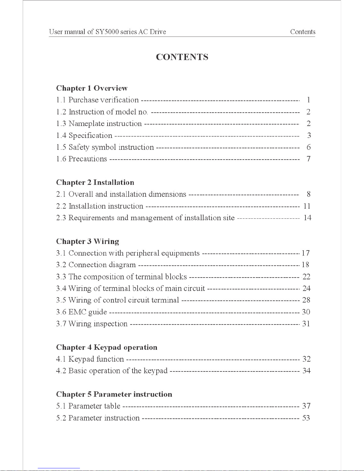
Chapter 1 Overview
Thank you for choosing SYRUNS SY5000 series AC Drive!
SY5000 series AC Drive is a high-quality, multi-function, low-noise inverter
which is designed, developed and produced according to international standards.
It can meet different needs of industrial conditions. It is applied advanced control
technology of space voltage PWM, with functions of constant voltage control,
power-off restart, dead zone compensation, automatic slip compensation, on-line
modication parameter. It is also with compact structure, easy to install.
For safety, please read the manual thoroughly before using SY5000 series
AC Drive. Meanwhile, please retain the manual and you can use it when regulate,
maintain and inspect the equipment in future.
The manual provides using instruction of SY5000 series AC Drive:
1. SY5000-G series general purpose AC Drive
2. SY5000-P series fan and pump purpose AC Drive
3. SYB-U50, SYB-U100 braking unit
4. Remote control keypad and extention cable
1.1 Purchase verication
Please verify the following items when open the box.
Table 1-1 Verication item
Verication item Verication method
Is it what you order, or not Please watch nameplate on the side of SY5000 AC Drive.
Parts damages or not Please check overall appearance.
Screws loose or not If necessary, use a screwdriver to check it.
If abnormal, please get in touch with the agent.
User Manual of SY5000 series AC Drive Overview
~2~
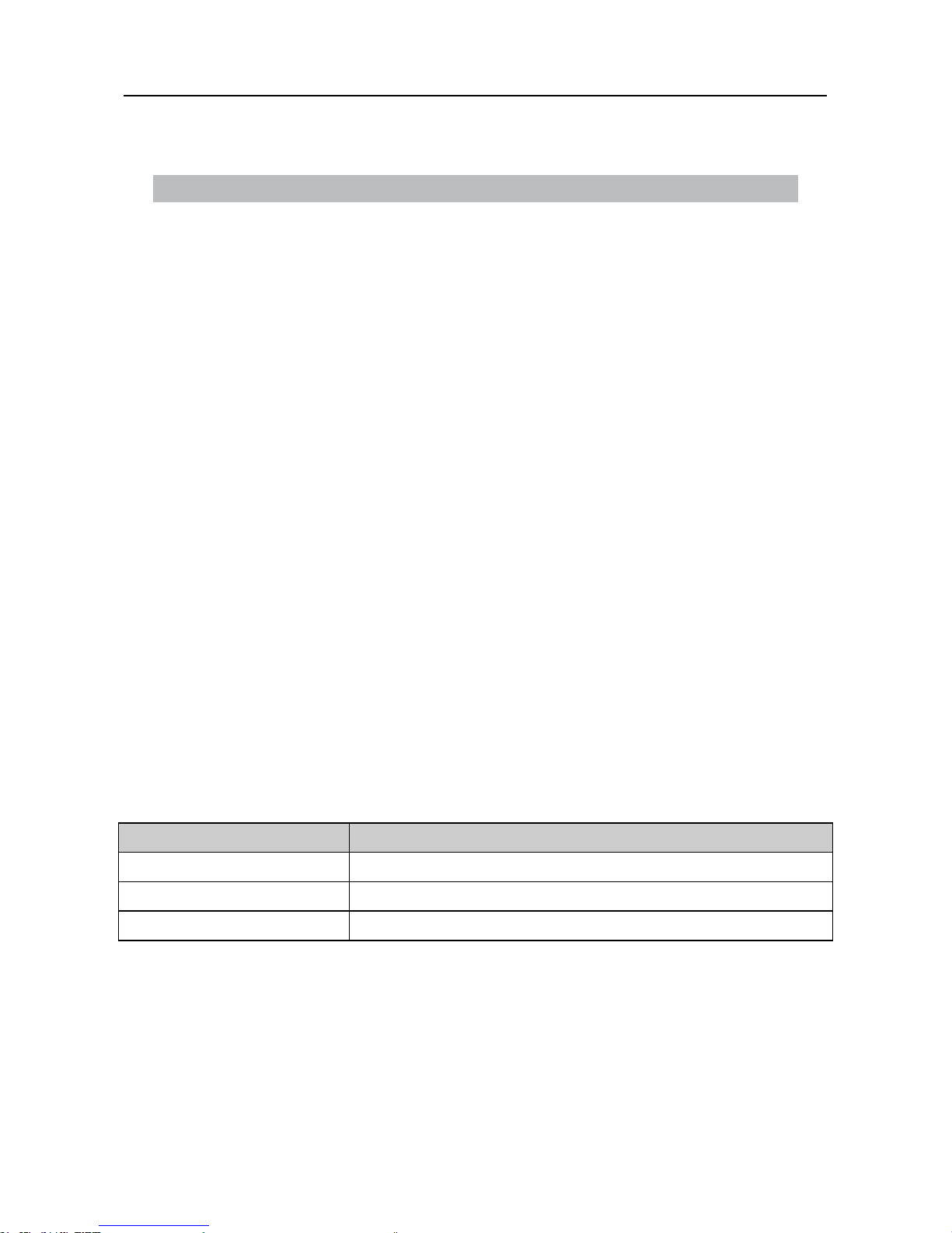
1.2 Instruction of model no.
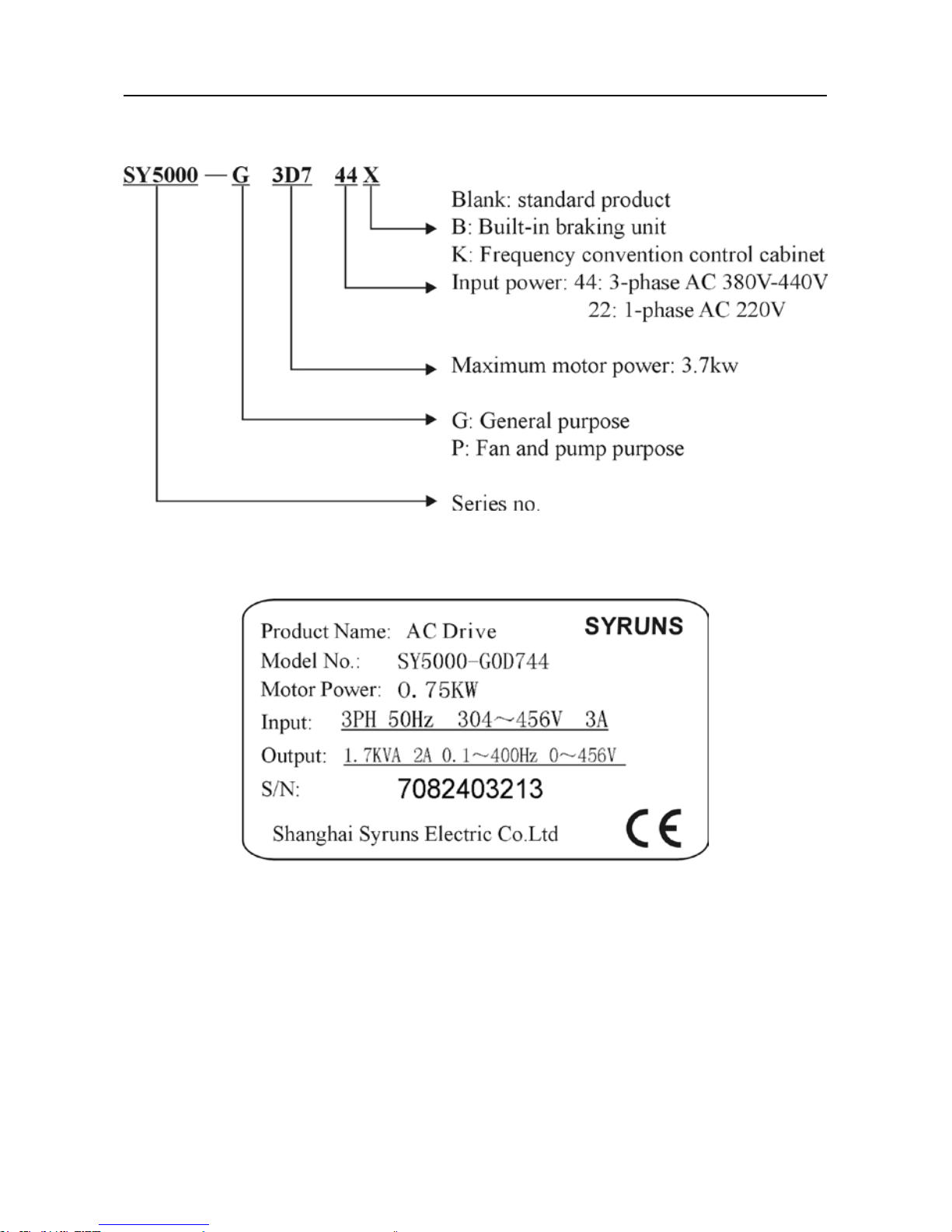
1.3 Nameplate instruction
User Manual of SY5000 series AC Drive Overview
~3~
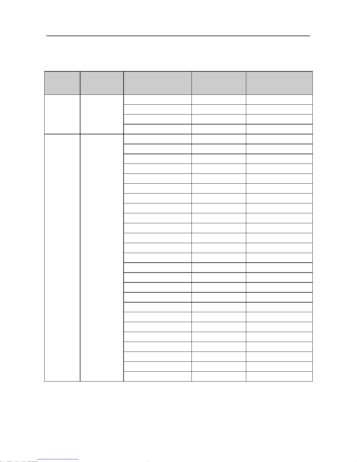
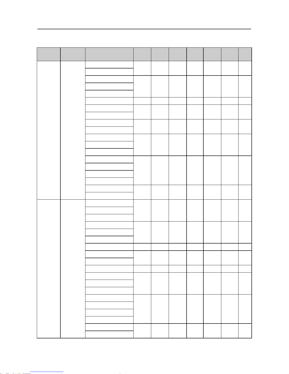
1.4 Specication of SY5000 series AC Drive
Table 1-2 Specication of SY5000 series AC Drive
Voltage
class
Item Model no.
Motor power
(KW)
Rated output
current (A)
Single
phase
220V
General
purpose
SY5000-G0D422 0.4 3
SY5000-G0D722 0.75 4.5
SY5000-G1D522 1.5
7
SY5000-G2D222 2.2 11
Three
phase
380V
General
purpose
SY5000-G0D744 0.75 2
SY5000-G1D544 1.5
4
SY5000-G2D244 2.2 5.5
SY5000-G3D744 3.7 8
SY5000-G5D544 5.5 13
SY5000-G7D544 7.5 17
SY5000-G01144
11 24
SY5000-G01544 15
33
SY5000-G01844 18.5
39
SY5000-G02244 22 44
SY5000-G03044 30 60
SY5000-G03744 37 75
SY5000-G04544 45 90
SY5000-G05544 55 110
SY5000-G07544 75 150
SY5000-G09044 90 175
SY5000-G11044 110 210
SY5000-G13244 132
255
SY5000-G16044 160
305
SY5000-G18544 185
340
SY5000-G20044 200 380
SY5000-G22044 220 425
SY5000-G24544 245 480
SY5000-G28044 280 545
SY5000-G31544 315 615

User Manual of SY5000 series AC Drive Overview
~4~
Three
phase
380V
Fan and
pump
purpose
SY5000-P3D744 3.7 8
SY5000-P5D544 5.5 13
SY5000-P7D544 7.5 17
SY5000-P01144
11 24
SY5000-P01544 15
33
SY5000-P01844 18.5
39
SY5000-P02244 22 44
SY5000-P03044 30 60
SY5000-P03744 37 75
SY5000-P04544 45 90
SY5000-P05544 55 110
SY5000-P07544 75 150
SY5000-P09044 90 175
SY5000-P11044 110 210
SY5000-P13244 132
255
SY5000-P16044 160
305
SY5000-P18544 185
340
SY5000-P20044 200 380
SY5000-P22044 220 425
SY5000-P24544 245 480
SY5000-P28044 280 545
SY5000-P31544 315 615
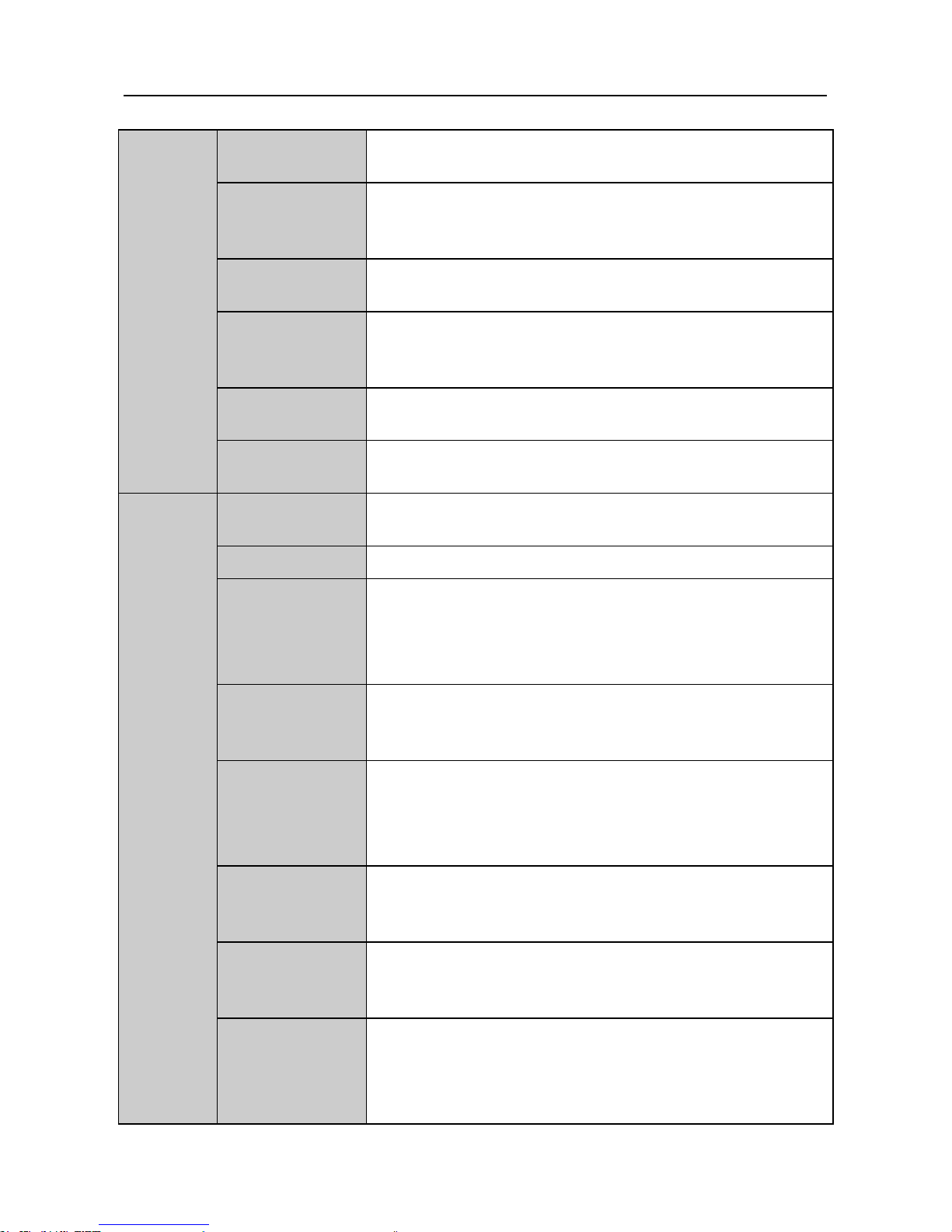
Table 1-3 Technical specication of SY5000 series AC Drive
Item Specication
Output
Output voltage
Single phase /triple phase corresponding input voltage,
constant voltage control is optional
Output frequency
range
0.10~650.00Hz; highest frequency can set freely between
25.00~650.00Hz
Power
Voltage,
frequency
1PH 220V
±
15%; 3PH 380V±15% 50Hz; 3PH 440V
±
10% 60Hz
Control
function
Control mode
Digital SVPWM space voltage vector control; carrier
frequency 1.0~16.0KHz adjustable continuously
Start frequency 0.00~25.00HZ setting freely
User Manual of SY5000 series AC Drive Overview
~5~
Control
function
Resolution of
output frequency
0.01Hz
Resolution of
frequency setting
Digital setting: under 100Hz:0.01HZ; others: 0.1Hz;
analog input (external terminal) setting: 1% of highest
frequency
V/F feature
Linear V/F: base frequency can be set freely between
25.00~650.00Hz
Torque
compensation
constant torque, 1.2-th power and 1.5-th power decreasing
torque compensation mode selectable, compensation
voltage range: 0~30%
DC braking
Start frequency(0.00~10.00Hz), voltage(0~15%),
duration(0.0~10.0s)can be set freely
Overload
capacity
General purpose: 150% rated current 1minute;
fan and pump purpose: 120% rated current 1 minute
Operation
function
Operation mode
FWD-REV, RUN/FWD-REV, FWD-REV/selfsustaining,3 modes available
Stop mode Deceleration stop/free stop
Frequency
setting
Operation panel▲▼key in, external potentiometer, panel
potentiometer external analog current signal DC4~20mA,
external anolog voltage signal DC0~5V or DC0~10V
Time mode of
accel /decel rate
0.1~6000.0 seconds (accel /decel can be set seperately)
No.1/No.2 accel /decel time, linear /S-curve type accel
/decel modes selectable
Multi-section
speed operation
8-section speed of the external terminal control or
4-section speed of parameters setting (one-cycle or repeat
cycle), each section can be set freely, accel /decel time of
speed, two methods selectable
Jog operation
Frequency(0~highest frequency), accel /decel
time(0.1~6000.0 seconds), accel /decel mode (linear/S
type) can be set freely
Frequency of
upper limit and
lower limit
Upper limit frequency (lower limit frequency~highest
frequency), lower limit frequency (0~upper limit
frequency) setting freely
Other functions
Fault recovery, jog frequency, external analog, input
bias/gain setting, speed display system, slip conpensation,
fault history record (4 times), dynamic parameter (part)
modify, anti-reverse, etc.
User Manual of SY5000 series AC Drive Overview
~6~
Input
output
signal
Operation panel Display: 5 data LED;parameter setting: 6 switches
External terminal
input
4 programmable inputs(PI1~PI4), FWD, REV, EMS,
RES
Fault output IC relay output (AC250V, 1A,resistance load)
Output with open
collector
OUT-COM: Signal in operation/signal of speed arrival
of detection rate/ signal of overload alarm are selectable
(Rated 24V, available output 50mA)
Frequency table
output
DC0~10V (max output current:10mA, resolution
ratio:0.4%), rated output frequency/rated current/rated
voltage are optional
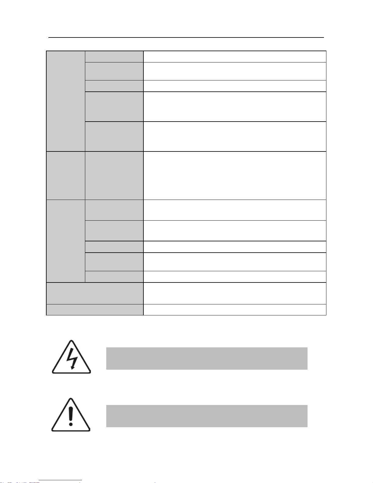
Protection
Protection
function
Overcurrent stalling protection (50~200% of rated
current), overvoltage stalling protection, overvoltage
protection,overcurrent protection, overload protection,
overheat protection, undervoltage protection, emergency
stop,etc.
Working
condition
Installation site
Indoor,altitude of less than 1km,dust free, non-corrosive
gases,no direct sunlight
Application
environment
0℃~+40℃,20%~90%RH (no dew)
Vibration Less than 0.5g
Storage
temperature
-25℃~+65℃
Mounting type Wall-mounted type, oor cabinet type
Protection degree
General purpose:IP20 (
≤
7.5kw); IP10 (≥11kw)
Fanand pump purpose:IP20 (
≤
11kw); IP10 (≥15kw)
Cooling mode Forced air cooling
1.5 Safety symbol instruction
It is very dangerous when use wrongly, possiblely make
people die.
Caution
Danger
It is dangerous if use wrongly, possiblely make people
injury or machine damage.

User Manual of SY5000 series AC Drive Overview
~7~
1.6 Precautions
1. The inverter just applies to general triple-phase AC induction motors or variable
frequency motors. The installation environment should be well ventilated.
2. It is a normal phenomenon that temperature and noise of the motor raise a little
higher than power frequency when use the inverter.
3. General motors can’t work long under low-speed.
4. Output terminal of the inverter cannot be connected with RC absorbing device,
such as capacitor, varistor, etc.
5. If install the contactor between the inverter and the motor, must ensure that the
inverter does not output when the contactor is on-off. Otherwise, it will damage
the inverter.
6. The inverter should be used derating if the altitude is higher than 1000 meters.
Derate 10% when the altitude rises 1500 meters.
7. The inverter is as industrial waste when scrap it. Please be careful:
(1)Inner polymer capacitors probably explode if set it on re.
(2)Plastic pieces may produce toxic gases when burn it.
User Manual of SY5000 series AC Drive Installation
~8~
Chapter 2 Installation
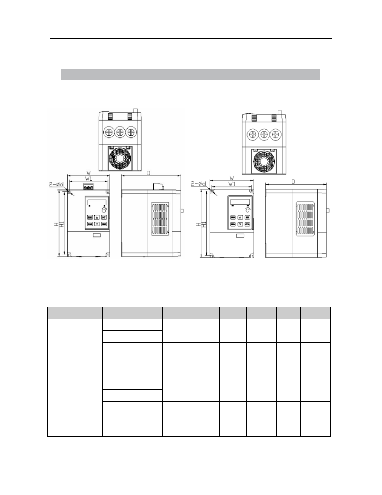
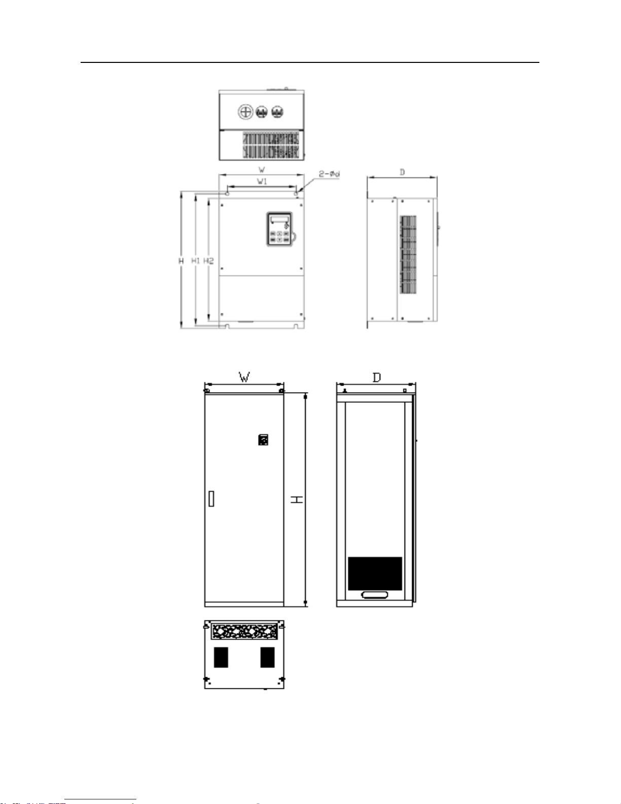
2.1 Overall and installation dimensions
(a) 0.75~2.2KW (b) 3.7~7.5KW
Figure 2-1 Overall of SY5000 series AC Drive
Table 2-1 Overall and installation dimensions of SY5000 series AC Drive
Voltage class Model no. W W1 H H1 D d
Single-phase
220V
SY5000-0D422
85
73 141.5 129.5 113 4.5
SY5000-0D722
SY5000-1D522
115 105 180 170 160 5
SY5000-2D222
Three phase
380V-440V
SY5000-0D744
SY5000-1D544
SY5000-2D244
SY5000-3D744 150 138 235 223 160 5
SY5000-5D544
190 178 300 288 179 6.5
SY5000-7D544
User Manual of SY5000 series AC Drive Installation
~9~
Figure 2-2 (a) 11KW~160KW
Figure 2-2 (b)
≥
185KW
User Manual of SY5000 series AC Drive Installation
~10~
Table 2-2 Overall dimensions(≥11KW)
Voltage
class
Type Model no. W W1 H H1 H2 D d
Three
phase
380V
General
purpose
SY5000-G01144
243 196 392 372 350 185 9.5
SY5000-G01544
SY5000-G01844
293 200 504 484 460 236 9.5SY5000-G02244
SY5000-G03044
SY5000-G03744 307 200 554 534 510 236 9.5
SY5000-G04544
390 300 620 590 560 248 10
SY5000-G05544
SY5000-G07544
430 300 860 800 830 340 12
SY5000-G09044
SY5000-G11044
570 500 900 870 840 375 13SY5000-G13244
SY5000-G16044
SY5000-G18544
610 — 1906 — — 605 —
SY5000-G20044
SY5000-G22044
SY5000-G24544
SY5000-G28044
730 — 2000 — — 605 —
SY5000-G31544
Three
phase
380V
Fan and
pump
purpose
SY5000-P01144
243 196 392 372 350 185 9.5
SY5000-P01544
SY5000-P01844
SY5000-P02244
293 200 504 484 460 236 9.5SY5000-P03044
SY5000-P03744
SY5000-P04544 307 200 554 534 510 236 9.5
SY5000-P05544
390 300 620 590 560 248 10
SY5000-P07544
SY5000-P09044 430 300 860 800 830 340 12
SY5000-P11044
570 500 900 870 840 375 13SY5000-G13244
SY5000-G16044
SY5000-G18544
610 — 1906 — — 605 —
SY5000-G20044
SY5000-G22044
SY5000-G24544
SY5000-G28044
730 — 2000 — — 605 —
SY5000-G31544
User Manual of SY5000 series AC Drive Installation
~11~
2.2 Installation instruction
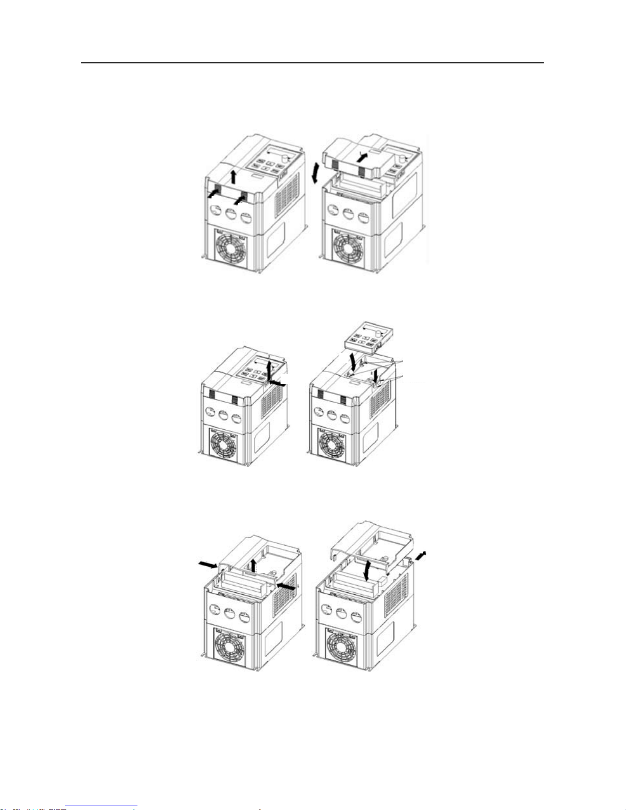
2.2.1 Disassembly and assembly of panel and keypad
(a) (b)
Figure 2-3 Disassembly and assembly of small panel
(a) (b)
Figure 2-4 Disassembly and assembly of keypad
(a) (b)
Figure 2-5 Disassembly and assembly of big panel
Claw locker A
Claw locker B
1
2
1
2
2
1
1
1
2
2
1

User Manual of SY5000 series AC Drive Installation
~12~
1. Disassembly and assembly of small panel (terminal cover)
(1) Disassembly of small panel
As shown in Figure 2-3 (a), press two faces according to direction 1, meanwhile,
lift lower part of small panel according to direction 2.
(2) Assembly of small panel
As shown in Figure 2-3 (b),when assembly,rstly align small panel and big panel,
lean panels forward, embed bayonet shapes of panel in big panel, and then press
down the panels according to direction 2.
2. Disassembly and assembly of keypad
(1) Disassembly of keypad
As shown in Figure 2-4 (a), press the buckle on the side of keypad according to
direction 1, unhook it from big panel, lift it according to direction 2, and then get the
keypad.
(2) Assembly of keypad
As shown in Figure 2-4 (b), stick Digital Console from the 1 directions the claw
locker A(place 2), pressing to keep toward 2 directions immediately after hearing the
“click”voice, stick the claw locker B (place 2).
3. Disassembly and assembly of big panel
(1) Disassembly of big panel
As shown in Figure 2-5 (a), make an effort toward 1 direction to press the two side
of console support, in the meantime, please press 2 directions to lift console support
lower part.
(2) Assembly of big panel
As shown in Figure 2-5 (b) , console support head two cards hang up to block from
the 1 directions the hull body(place 2), press to keep toward 2 directions immediately
after hearing the“click”voice.
2.2.2 Disassembly and assembly of terminal housing and keypad (≥11 kW)
1. Disassembly and assembly of terminal housing
(1) Disassembly of terminal housing
Use standard No. 1 crosshead screwdriver to take off two M4 screw bolts (as shown
in Figure 2-6 (a)), and then you can remove the terminal housings.
(2) Assembly of terminal housing
Use two M4 × 8 bolts to x terminal housings (The direction is as shown in Figure
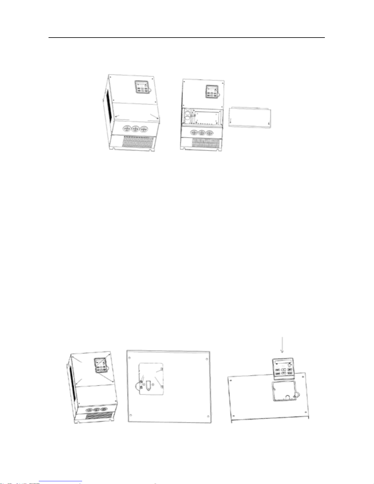
User Manual of SY5000 series AC Drive Installation
~13~
2-7(b)), and tighten by using standard No.1 crosshead screwdriver, and tightening
torque is about 5 ~ 8 N • m.
(a) (b)
Figure 2-6 Disassembly and assembly of terminal housing and keypad (≥11 kW)
2. Disassembly and assembly of keypad
(1) Disassembly of keypad
◆ Use standard No.1 crosshead screwdriver to take off four M4 bolts(as shown in
Figure 2-7 (a) );
◆ Disconnect the connection cable of keypad, and remove control panel;
◆ As shown in Figure 2-7 (b), rollover control panel, push out the jaw of keypad,
and remove keypad.
(2) Assembly of keypad
◆ As shown in Figure 2-7 (c), rstly inbed keypad in keypad adapter, and conrm
the correction of inbedding in the slotted hole;
◆ Connect the connection wire of keypad with control circuitboard;
◆ Fix control panel on the box by using four M4×8 bolts, and tighten by using
standard No.1 crosshead screwdriver, and tightening torque is about 5 ~ 8 N • m.
(a) (b) (c)
Figure 2-7 Disassembly and assembly of keypad (≥11kW)
screw hole
screw
hole
clasp
User Manual of SY5000 series AC Drive Installation
~14~
2.3 Requirements and management of installation site
2.3.1 Installation site:
The installation site should meet the following conditions:
Good indoor ventilation
Ambient temperature -10°C~40°C
Humidity less than 90%RH, without dew
Don’t install in the combustibles such as woods
Avoid direct sunlight
No combustible, explosive, corrosive gases and liquids
No ash dust, oil dust, oatable bers and metal particles
strong installed base, no vibration
No electromagnetic interference
Caution
3. Please hold the bottom of AC Drive when carry it.
Risk of feet injury if only holding the panel.
4. Please install in metal board and other nonammable materials.
Risk of re if installing in ammable materials.
5. If install two or more AC Drives in the same cabinet, please set the cooling fan,
and keep the air temperature below 40℃.
Risk of re and other accidents if overheating.
1. In order to avoid being exposed and damaged, don’t use other methods to
disassembly and assembly keypad and panels.
2. Don’t directly install big panel with keypad in the AC Drive, otherwise, it will
bring poor contact.Please separately install big panel in the AC Drive, then
install keypad in the big panel.
Caution
User Manual of SY5000 series AC Drive Installation
~15~
2.3.2 Ambient temperature
To improve operation reality of AC Drive, please install in well-ventilated place.
When used in an enclosed cabinet, install the cooling fan or cooling air-conditioning,
and keep the environment temperature below 40°C.
2.3.3 Precaution
Please put a dust cover on the AC Drive when install. Do not fall metal framents
into AC Drive internal when drill holes. Please remove dust cover after installation
nishes.
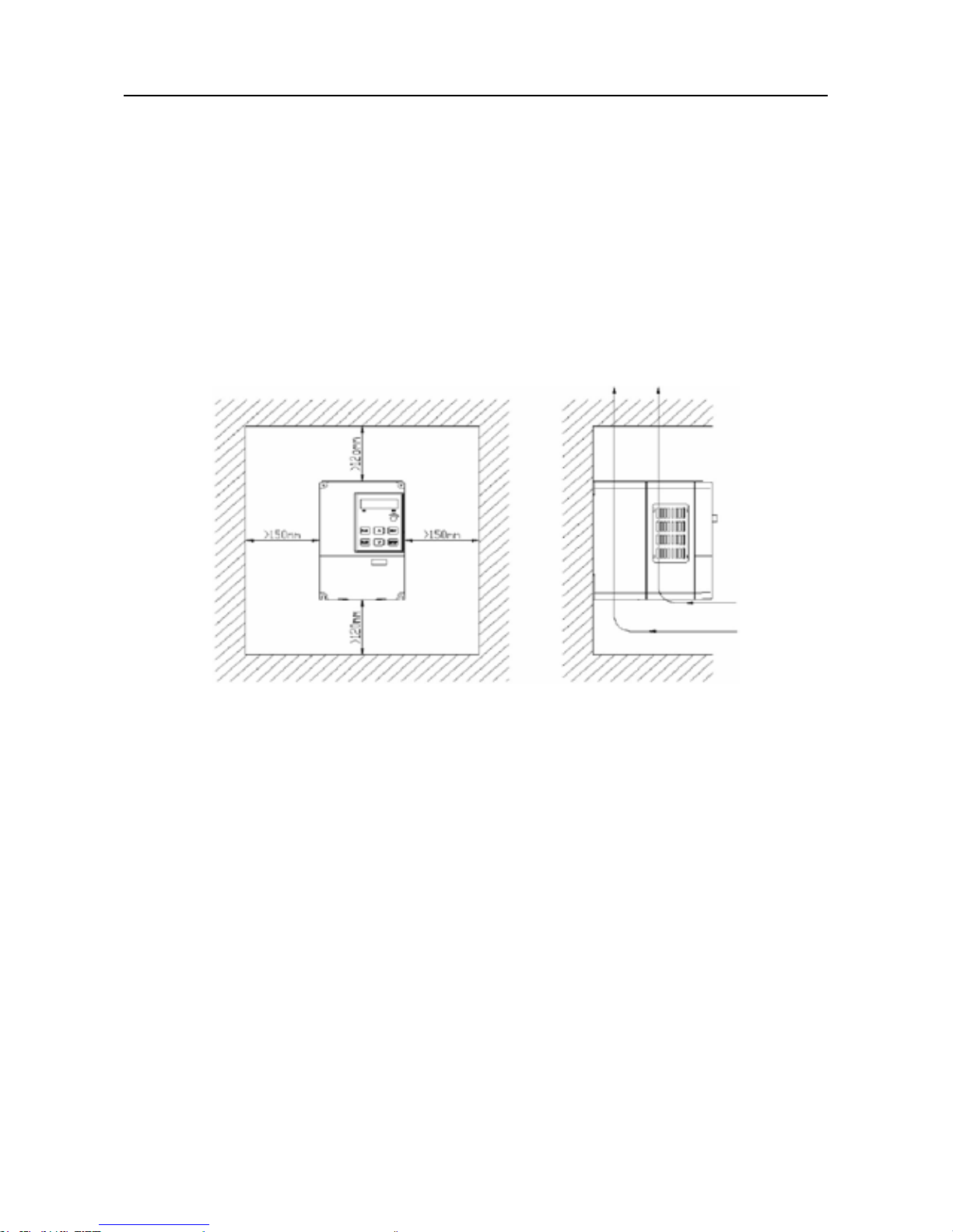
2.3.4 Installation direction and space
Figure 2-8 Installation direction and space of SY5000 series AC Drive
In order to get good effect of cooling cycle, must install the AC Drive in vertical
direction. Please refer to Figure 2-8.
*********************************************************************
Note: When install two AC Drives upper and lower, we should utilize isolating plate.
*********************************************************************
User Manual of SY5000 series AC Drive Wiring
~16~
Chapter 3 Wiring
Danger
Caution
1 Before wiring, please conrm the cut-off of input power supply.
Risk of electric shock and re.
2 Wiring operations must be carried out by electric engineerting specialists.
Risk of electric shock and re.
3 Ground terminal must be reliably grounded.
(380V class:especially the third
ground)Risk of electric shock and re.
4 After connecting with the terminal of emergency stop, be sure to check the
validity of actions.Risk of injury.(The responsibility of wrong wiring is
undertaked by users.)
5 Do not directly touch the output terminals. Do not connect the output terminals of
inverter with the housings. Do not be short circuit between output terminals.
Risk of electric shock and short-circuit.
1 Make sure rated voltages of AC main circuit power supply and inverter are the
same. Risk of injury and electric shock.
2 Do not test withstand voltage of inverter.
It will damage semiconductor components.
3 Please connect braking unit or braking resistor according to wiring diagram.
Risk of re.
4 Please use the specied torque screwdriver fastening terminals. Risk of re.
5 Do not connect the cable of input power supply to output U
、V、W terminals.
It will damage the internal of the inverter if adding voltage onoutput terminals.
6 Do not switch phase-shift capacitor into output circuit. It will damage the internal
of the inverter.
7 Do not switch electric-magnetic switch and electric-magnetic contactor into ouput
circuit. When the inverter is in operation with a load, surge current generated by
electromagnetic switches, electromagnetic contactors will cause the over-current
protection circuit action of inverter.

User Manual of SY5000 series AC Drive Wiring
~17~
3.1 Connection with peripheral equipments
SY5000 series inverter standard connection diagram with peripheral equipments
(As shown in Figure 3-1)
Figure 3-1 Connection diagram with peripheral equipments
User Manual of SY5000 series AC Drive Wiring
~18~
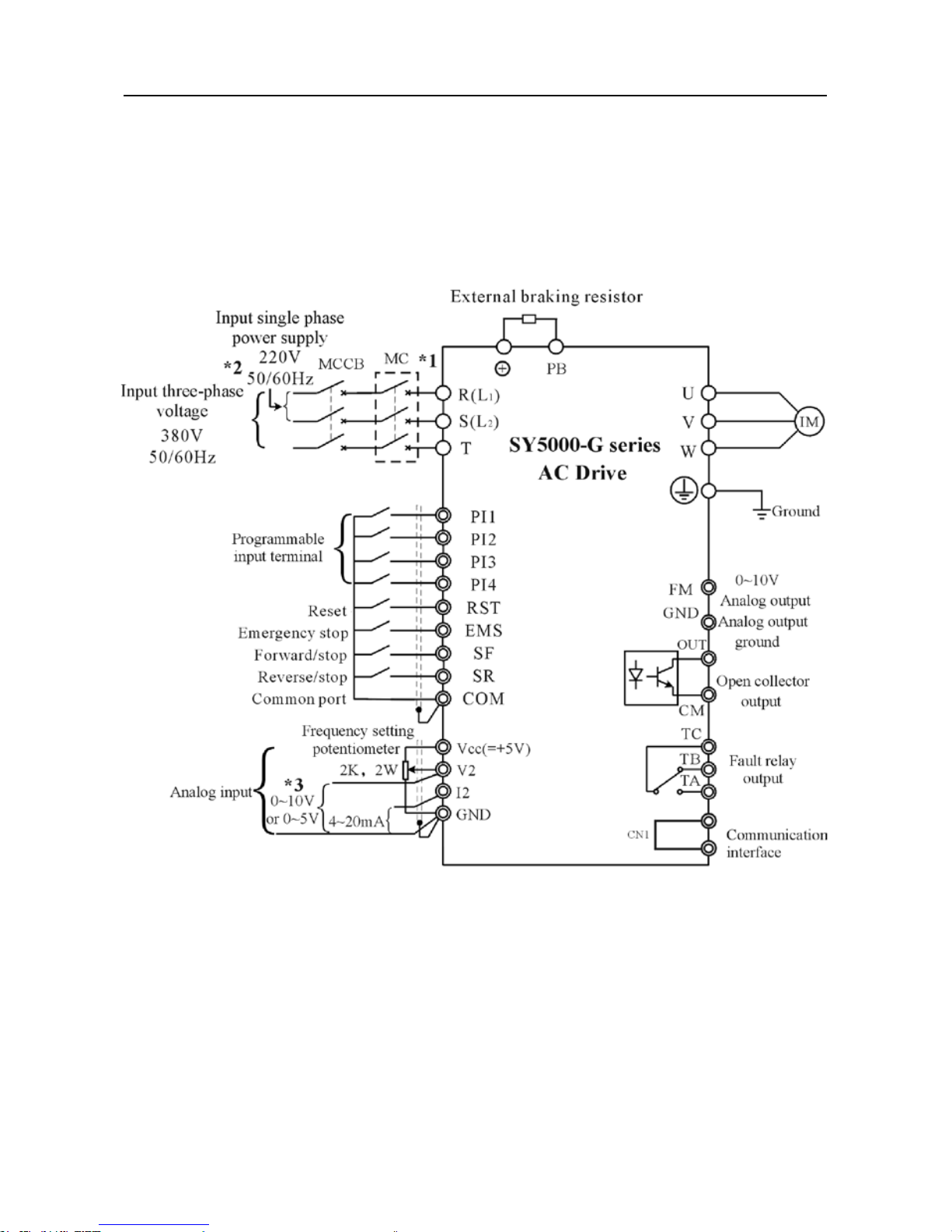
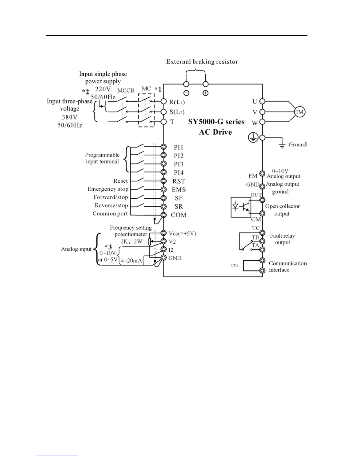
3.2 Connection diagram
Figure 3-2a,3-2b,3-3a,3-3b are connection diagrams of SY5000 series
inverter. When manipulate the inverter by using keyboard of control panel, the electric
motor can work only when connect main circuit.
Figure 3-2a Connection diagram of SY5000-G series (≤15KW)
User Manual of SY5000 series AC Drive Wiring
~19~
Figure 3-2b Connection diagram of SY5000-G series (≥18.5KW)
User Manual of SY5000 series AC Drive Wiring
~20~
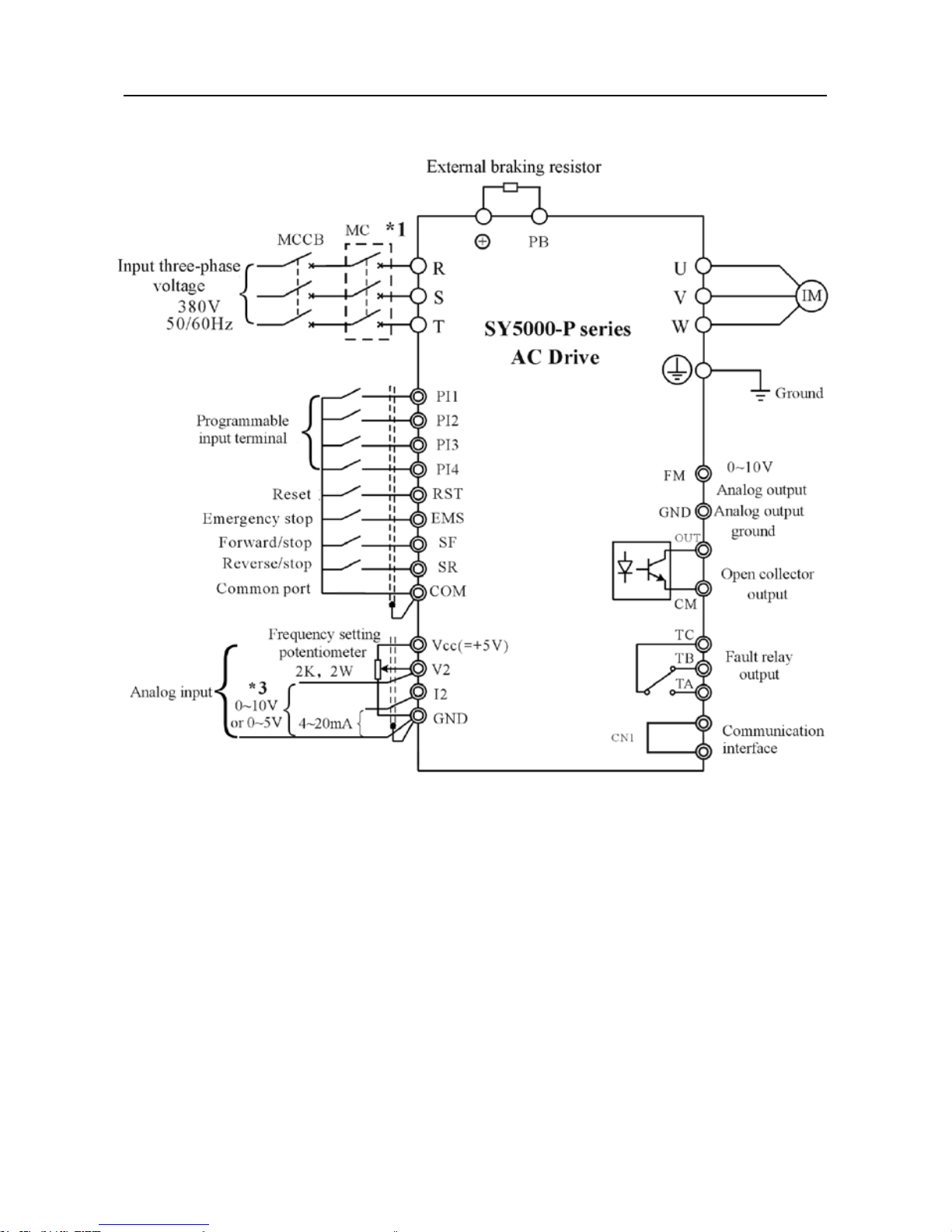
Figure 3-3a Connection diagram of SY5000-P series (≤18.5KW)
User Manual of SY5000 series AC Drive Wiring
~21~
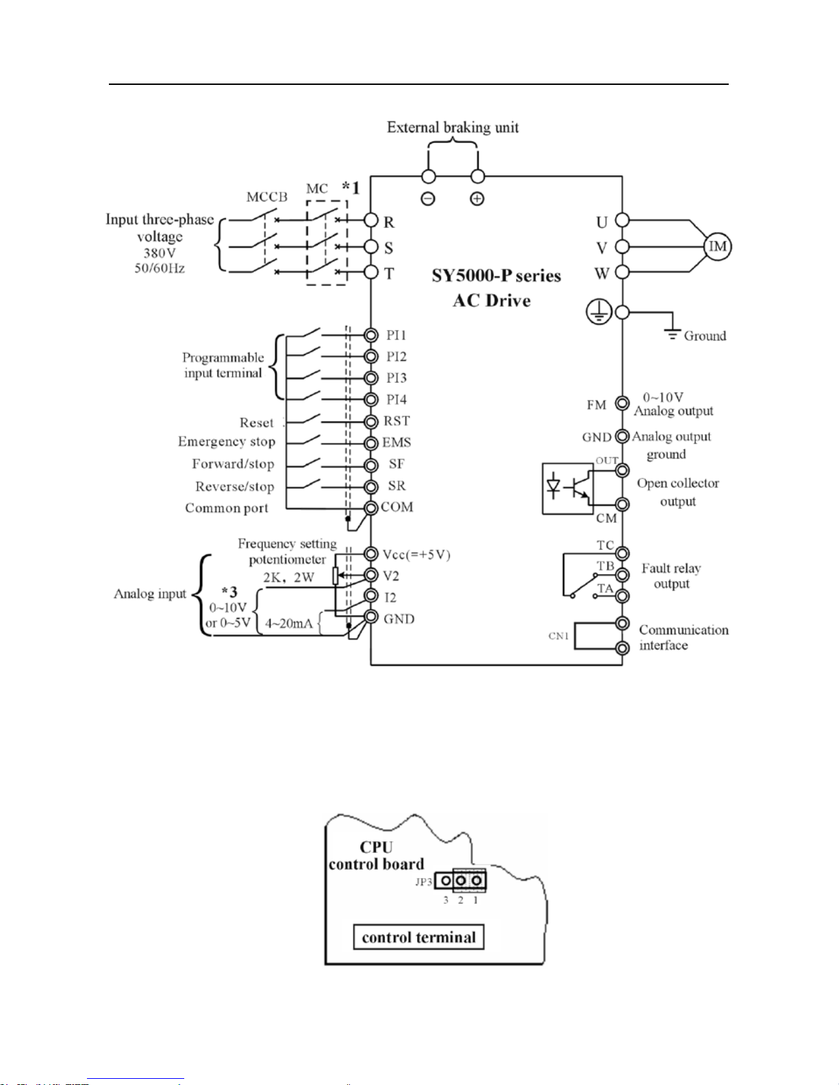
Figure 3-3b Connection diagram of SY5000-P series (≥22KW)
Remark:
*1:MC is mainly used to prevent fault re-start or transcient power-cut re-start;
Resistor overheat protection of external braking unit also should be connected to the
control loop of MC.
*2:For 220V series,input power supply switches in L
1,L2
;for 380V, inputpower
User Manual of SY5000 series AC Drive Wiring
~22~
supply switch in R, S, T;
*3:Be decided by JP3 jumpers of CPU board: Located in position 1, input voltage
range of external analog voltage V2 is 0~5V;located in position 3, input voltage
range of V2 is 0~10V. If no special requirements before delivery, JP3 jumper is locaed
in position 1, namely input voltage range of V2 is 0~5V. See above gure。
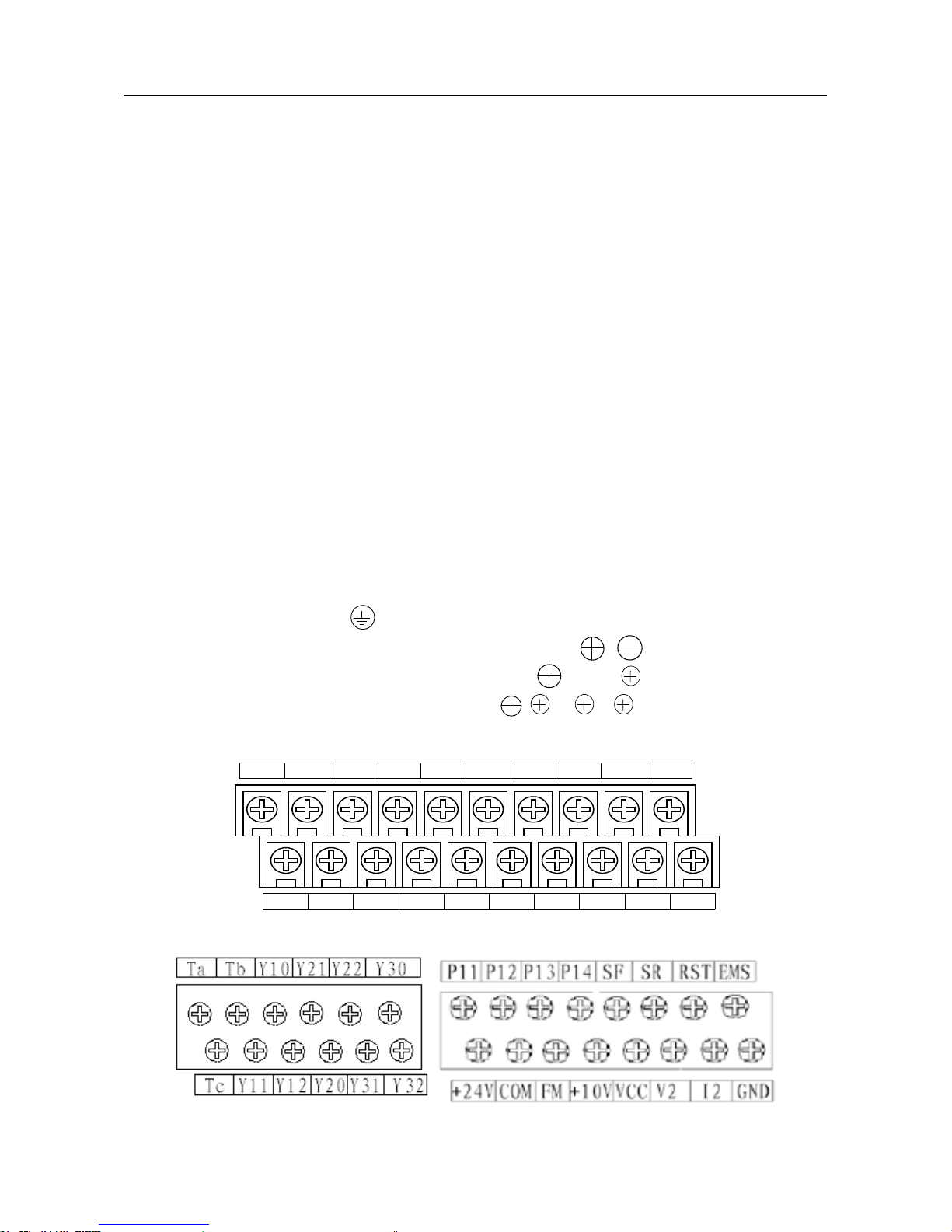
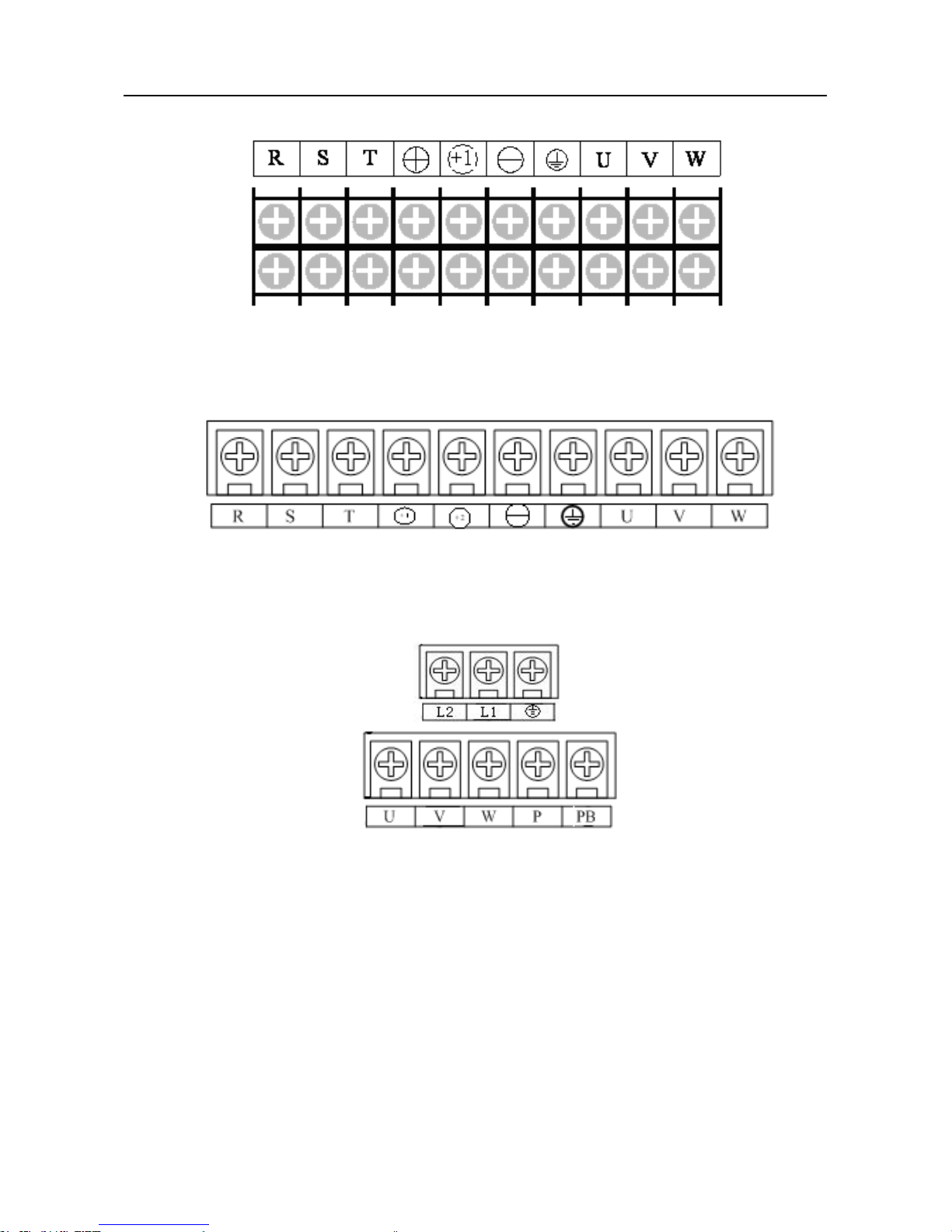
3.3 The composition of terminal blocks
Terminal blocks of SY5000 series inverter include terminal blocks of control
circuit and terminal blocks of main circuit:
Terminal block of general control circuit
1 Analog input:0~5V(0~10V)voltage source V2, 4~20mA current source
I2, GND
2 Digital input:SF, COM, SR, RST, EMS, PI1, PI2, PI3, PI4.
3 Digital output:OUT, TA, TB, TC
4 Analog output:FM
5 Signal of power supply:+5V voltage source Vcc, +24V power supply
Terminal block of main circuit
1 Input power supply
:R(L1), S(L2), T
2 Ground terminal:
3 Connection terminal of external braking unit: ,
4 Connection terminal of braking resistor: , PB和 2, PB
5 Connection terminal of DC reactor
: 1, 1 2
6 Electrical wiring:U, V, W
PI1 PI2 PI3 PI4 SF SR RST EMS FM GND
Ta Tb Tc
COM
OUT VCC V2 I2
GND
+24V
Terminal blocks of SY5000-G series control circuit
Terminal blocks of SY5000-P series control circuit

User Manual of SY5000 series AC Drive Wiring
~23~
R S T PB U V W
1 2
terminal blocks of main circuit (3PH 380V)
5.5, 7.5KW (SY5000-G series)
7.5, 11KW (SY5000-P series)
R S T
U V W PB
terminal blocks of main circuit (3PH 380V)
0.75~2.2KW (SY5000-G series)
3.7KW (SY5000-P series)
U V W
PB
R S T
terminal blocks of main circuit (3PH 380V)
3.7KW (SY5000-G series)
5.5KW (SY5000-P series)
Terminal blocks of main circuit (3PH 380V)
11KW, 15KW (SY5000-G series)
15KW, 18.5KW (SY5000-P series)
User Manual of SY5000 series AC Drive Wiring
~24~
Terminal blocks of main circuit (3PH 380V)
18.5KW~37KW (SY5000-G series)
22KW~45KW (SY5000-P series)
Terminal blocks of main circuit (3PH 380V)
45KW~90KW (SY5000-G series)
55KW~110KW (SY5000-P series)
Terminal blocks of main circuit (1PH 220V)
Figure 3-4 Arrangement of terminal blocks of control circuit and main circuit
3.4 Wiring of terminal blocks of main circuit
3.4.1 Cable size of main circuit and pressure wire terminals
Cable size and terminal screw size of main circuit, as shown in Figure 3-1
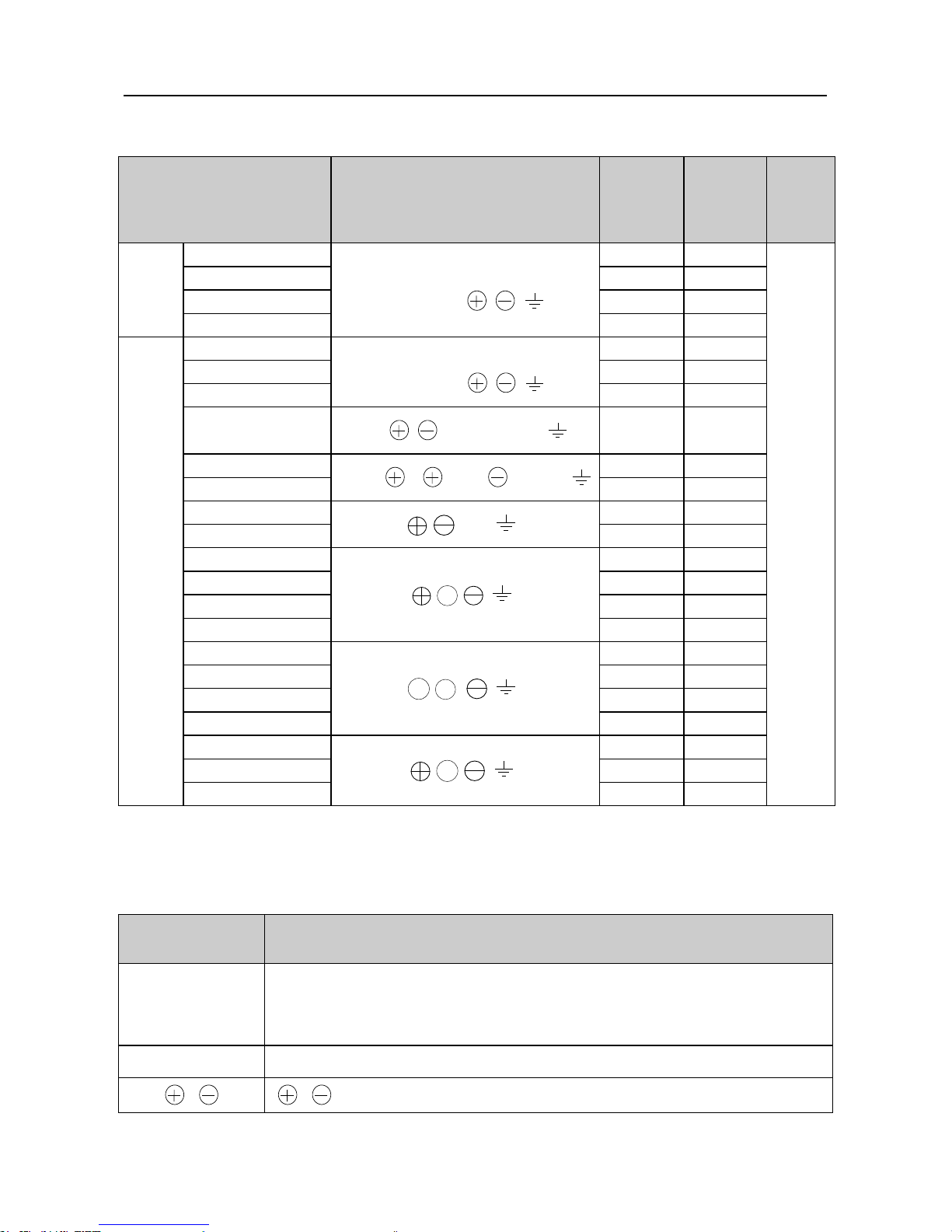
User Manual of SY5000 series AC Drive Wiring
~25~
Figure 3-1 terminal screw size and sectional area of wire
Model no. Terminal symbol
Terminal
screw
Sectional
area of
wire
(mm2)
Wire
species
1PH
220V
SY5000-G0D422
L1,L2
U,V,W,PB, , ,
M2.5 2.5
750V
plastic
cable
SY5000-G0D722
M2.5 2.5
SY5000-G1D522 M4 4
SY5000-G2D222 M4 6
3PH
380V-
440V
SY5000-G0D744
R,S,T,
U,V,W,PB, , ,
M4 2.5
SY5000-G1D544 M4 2.5
SY5000-G2D244 M4 4
SY5000-G3D744
PB, , ,R,S,T,U,V,W,
M4 4
SY5000-G5D544
R,S,T, 1, 2,PB, ,U,V,W,
M5 6
SY5000-G7D544 M5 6
SY5000-G01144
R,S,T, , ,PB , ,U,V,W
M5 8
SY5000-G01544
M5
8
SY5000-G01844
R,S,T, ,+1, , ,U,V,W
M6 16
SY5000-G02244 M6 16
SY5000-G03044
M6 25
SY5000-G03744 M8 25
SY5000-G04544
R,S,T, +1,+2, , ,U,V,W
M8 35
SY5000-G05544
M8 35
SY5000-G07544 M10 60
SY5000-G09044 M10 60
SY5000-G11044
R,S,T, ,+1, , ,U,V,W
M10 60
SY5000-G13244 M12 100
SY5000-G16044 M12 100
3.4.2 Function of main circuit terminal
Terminal function of main circuit, as shown in gure 3-2
Table 3-2 Function of main circuit terminal
Terminal
sign
Function description
R(L1),
S(L2), T
AC power supply input terminal:connect 3PH AC power supply
(R, S, T)(3PH 380V series) or 1PH AC power supply(L1,
L2)(1PH 220V series)
U, V, W Inverter output terminal, which is connected to 3PH AC motor.
, , respectively are anode and cathode of DC bus.
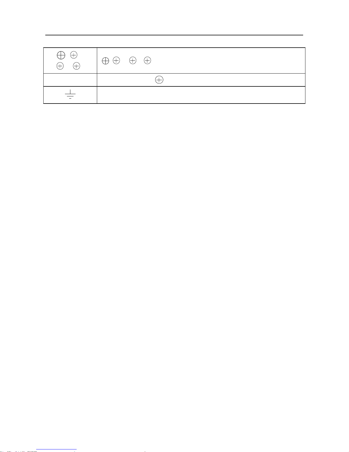
User Manual of SY5000 series AC Drive Wiring
~26~
, 1,
1, 2
1, 1 2 are DC reactor terminals of main circuit
PB
Between PB and is the terminal of built-in braking resistor
Ground terminal,grounding
3.4.3 Precautions of main circuit wiring
1. Installation of ELCB
As the inverter’s output is high-frequency PWM signal, the inverter will generate
high-frequency leakage current, please select Y2 type delay leakage circuit breaker
with above 30mA current sensitivity; if use ordinary ELCB, please select ELCB with
above 200mA current sensitivity.
2. Connection with terminal blocks
The phase sequence of input power supply is irrevelant to R(L1), S(L2), T phase
sequences of terminal block, so it can be any connection.
3. Setting of AC reactor or DC reactor
When the input power is connected with capacitive load, it will generate high peak
current in power grid.
If don’t take appropriate measures, the peak current may damage inverter rectier
and other power modules.
When there is high peak current in power grid, please connect 3PH AC reactor
(optional) on the power input side of inverter, or install DC reactor on the terminal of
DC reactor.
Therefore, it not only suppresses peak current, but also improves power factor.
4. Setting of Surge Protection Device (SPD)
When there is inductive load near the inverter (electromagnetic contactor,
electromagnetic valve, electromagnetic coil, electromagnetic circuit breaker), please
install SPD at two ends of its coil.
5. Wiring of inverter and electric motor
Please check whether rotate forwards when conrm the command of forward.
When the motor is reverse rotation, exchanging any two of U, V, W output
terminals can change rotation direction of the motor.
Use jog function to conrm forward and reverse rotations.
User Manual of SY5000 series AC Drive Wiring
~27~
6. Absolutely prohibit the connection of power supply wire and output terminal
Don’t connect the input power line to the output terminal.
If you input the power at the output terminal, the internal components of inverter
will be damaged.
7. Absolute prohibit short-circuit or grounding of output terminal
Do not directly touch the output terminal. Do not short the output line with inverter
housing. Otherwise, there will be danger of electric shock and short circuit.
In addition, don’t short the output line.
8. Absolutely prohibit the use of phase-shift capacitor
Don’t connect the capacitor in the output circuit. It will cause the damage of the
inverter.
9. Absolutely prohibit the use of electromagnetic switch
Don’t connect electromagnetic switches and electromagnetic contactors.
Otherwise, inverter surge current will cause protection action, and that will damage
interial components when it’s serious.
10. Wiring distance between inverter and motor
The longer wiring distance between the inverter and the motor, the higher high-
harmonic leakage current of the cable.
Leakage current will negatively impack the inverter and near equipments. Then it
should minimize the leakage current.
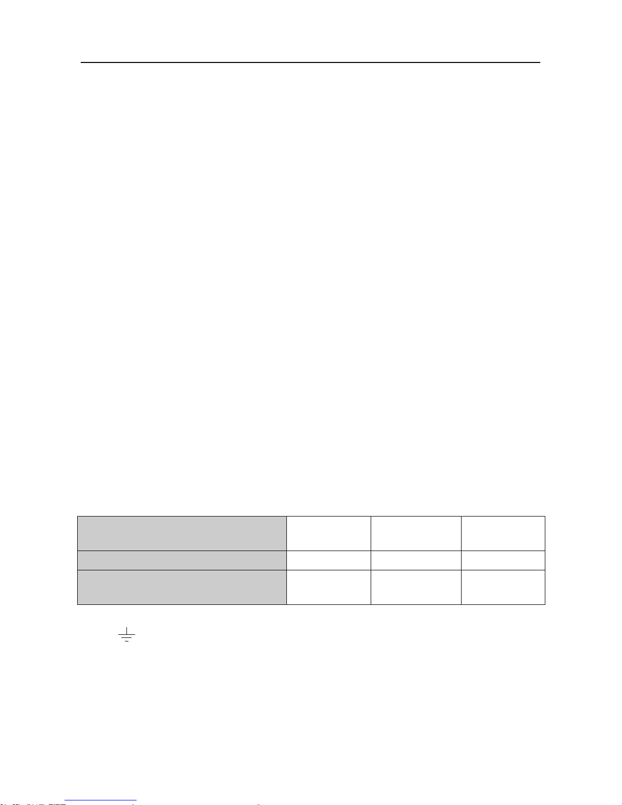
Wiring distance and carrier frequency are as shown in Table 3-3:
Table 3-3 Wiring distance and carrier frequency between inverter and motor
Wiring distance between inverter
and motor
Below 50m Below 100m Above 100m
Carrier frequency Blow 12KHz Below 10KHz Below 5KHz
Function code of parameter b-026
≤12.0 ≤10.0 ≤5.0
11. Ground connection
①
Ground terminal, please connect the ground.
220V series:type 3 ground(grounding resistance is less than 100Ω)
380V series:special type 3 ground(grounding resistance is less than 10Ω)
②
Don’t share the grounding line with welding machines or power equipments.
③
Please use the grounding wire according to electrical equipments technical
standards. And the distance from the ground is as short as possible.

User Manual of SY5000 series AC Drive Wiring
~28~
④
Don’t form the grounding line to a loop in the place when use two or more
inverters. Correct and wrong grounding methods are as shown in Figure 3-5.
Figure 3-5 Grounding comection
3.5 Wiring of control circuit terminal
In order to reduce interference and attenuation of control signal, wire length of
control signal should be less than 20m. The interval distance between wire length
and power line should be more than 30cm. Control signal line should be twisted-pair
shield cable.
3.5.1 Wire size and line terminal of general control circuit
Table 3-4 Size of terminal and wire and tightening torque of screw
Terminal
screw
Sectional area of wire
(mm2)
Wire type
Tightening torque
of screw(N·m)
M3.5 0.5~2
Multi-unit
shield wire
0.8
 Loading...