

Page 1

User manual
Product Name:ESP Module
Model Name:0037
Manufacture:Syrp Limited
Page 1
Page 2

www.Syrp.co.nz
Contents
1, Overview ............................................................................................................................................. 3
2 Pin Definitions ..................................................................................................................................... 4
2.1 Pin Layout ...................................................................................................................................... 4
2.2 Pin Description .............................................................................................................................. 5
2.3 Strapping Pins ............................................................................................................................... 5
3 functional Description ......................................................................................................................... 7
3.1 CPU and Internal Memory ............................................................................................................ 7
3.2 External Flash and SRAM .............................................................................................................. 7
3.3 Crystal Oscillators .......................................................................................................................... 7
3.4 RTC and Low-Power Management ............................................................................................... 7
4. Peripherals and Sensors ..................................................................................................................... 9
4.1 Peripherals and Sensors Description ............................................................................................ 9
5. Electrical Characteristics .................................................................................................................. 14
5.1 Absolute Maximum Ratings ........................................................................................................ 14
5.2 Wi-Fi Radio .................................................................................................................................. 14
5.3 BLE Radio ..................................................................................................................................... 15
5.3.1 Receiver .................................................................................................................................... 15
5.3.2 Transmitter .............................................................................................................................. 15
5.4 Reflow Profile .............................................................................................................................. 16
6. ESP32-PICO-D4 Schematics .............................................................................................................. 17
7. ESP32-0031-7002 Schematics .......................................................................................................... 18
8. Peripheral Schematics ...................................................................................................................... 19
9 Learning Resources ............................................................................................................................ 20
9.1 Must-Read Documents ............................................................................................................... 20
9.2 Must-Have Resources ................................................................................................................. 20
Page 2
Page 3
www.Syrp.co.nz
1, Overview
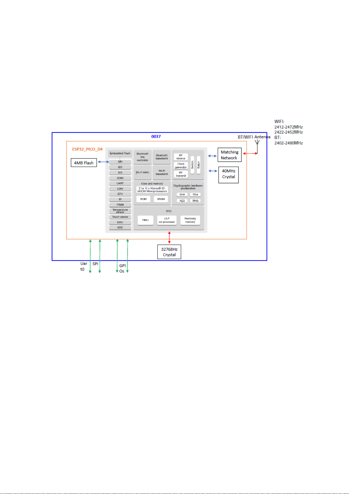
ESP32-0037-7002 is a wireless product, which mainly includes an ESP32-PICO-D4, a 32768Hz
crystal and a 2.4GHz antenna. See the block diagram as Figure 1. 0037-7002 provides the WIFI and
Blue Tooth (BLE) functions.
The ESP32-PICO-D4 is a System-in-Package (SIP) module that is based on ESP32, providing
complete Wi-Fiand Bluetooth functionalities. The module integrates a 4-MB SPI flash.
At the core of this module is the ESP32 chip, which is a single 2.4 GHz Wi-Fi and Bluetooth combo
chip. ESP32-PICO-D4 integrates all peripheral components seamlessly, including a crystal oscillator,
flash, filter capacitors and RF matching links in one single package.
Figure 1 Block diagram of ESP32-0037-7002
Page 3
Page 4
2 Pin Definitions
www.Syrp.co.nz
2.1 Pin Layout
Pin 1
Pin 30
Pin 2
Pin 29
Pin 3
Pin 4
Pin 5
Pin 6
Pin 7
Pin 8
Pin 9
Pin 28
Pin 27
Pin 26
Pin 25
Pin 24
Pin 23
Pin 22
Pi
n
Pi
n
Figure 2 Pin Layout of ESP32-0037-7002
Pi
n
Pin Pi
n
Pi
n
Pi
n
Pi
n
Pi
n
Pi
n
Pi
n
Pi
n
Page 4
Page 5

www.Syrp.co.nz
2.2 Pin Description
Table 2: Pin Description
No. Name Type Function
1
2
3
4
5
6
7
8
9
10 VDD P Power supply (2.3V ~ 3.6V)
11 IO13 I/O GPIO13, ADC2_CH4, TOUCH4, RTC_GPIO14, MTCK, HSPID,
12 IO15 I/O GPIO15, ADC2_CH3, TOUCH3, MTDO, HSPICS0,
13 IO2 I/O GPIO2, ADC2_CH2, TOUCH2, RTC_GPIO12, HSPIWP,
14 IO0 I/O GPIO0, ADC2_CH1, TOUCH1, RTC_GPIO11, CLK_OUT1,
15 IO4 I/O GPIO4, ADC2_CH0, TOUCH0, RTC_GPIO10, HSPIHD,
16 IO21 I/O GPIO21, VSPIHD, EMAC_TX_EN
17 IO22 I/O GPIO22, VSPIWP, U0RTS, EMAC_TXD1
18 IO5 I/O GPIO5, VSPICS0, HS1_DATA6, EMAC_RX_CLK
19 IO18 I/O GPIO18, VSPICLK, HS1_DATA7
20 IO23 I/O GPIO23, VSPID, HS1_STROBE
21 GND P Ground
22 VDD P Power supply (2.3V ~ 3.6V)
23 VDD P Power supply (2.3V ~ 3.6V)
24 IO19 I/O GPIO19, VSPIQ, U0CTS, EMAC_TXD0
25 NC - Not Connected
26 U0RXD I/O GPIO3, U0RXD, CLK_OUT2
27 U0TXD I/O GPIO1, U0TXD, CLK_OUT3, EMAC_RXD2
28 NC - Not connected
29 VDD P Power supply (2.3V ~ 3.6V)
30 GND P Ground
EN I Chip-enable signal. Active high.
IO34 I GPIO34, ADC1_CH6, RTC_GPIO4
IO35 I GPIO35, ADC1_CH7, RTC_GPIO5
IO25 I/O GPIO25, DAC_1, ADC2_CH8, RTC_GPIO6, EMAC_RXD0
IO26 I/O GPIO26, DAC_2, ADC2_CH9, RTC_GPIO7, EMAC_RXD1
IO27 I/O GPIO27, ADC2_CH7, TOUCH7, RTC_GPIO17, EMAC_RX_DV
IO14 I/O GPIO14, ADC2_CH6, TOUCH6, RTC_GPIO16, MTMS,
HSPICLK,HS2_CLK, SD_CLK, EMAC_TXD2
IO12 I/O GPIO12, ADC2_CH5, TOUCH5, RTC_GPIO15, MTDI, HSPIQ,
HS2_DATA2, SD_DATA2, EMAC_TXD3
GND P Ground
HS2_DATA3, SD_DATA3, EMAC_RX_ER
RTC_GPIO13,HS2_CMD, SD_CMD, EMAC_RXD3
HS2_DATA0, SD_DATA0
EMAC_TX_CLK
HS2_DATA1, SD_DATA1, EMAC_TX_ER
2.3 Strapping Pins
ESP32 has five strapping pins, which can be seen in Section 5 Schematics:
• MTDI
• GPIO0
• GPIO2
• MTDO
• GPIO5
Software can read the value of these five bits from the register ”GPIO_STRAPPING”.
During the chip power-on reset, the latches of the strapping pins sample the voltage level as strapping
bits of ”0” or ”1”, and hold these bits until the chip is powered down or shut down. The strapping bits
configure the device boot mode, the operating voltage of VDD_SDIO and other system initial settings.
Page 5
Page 6
www.Syrp.co.nz
Each strapping pin is connected with its internal pull-up/pull-down during the chip reset. Consequently,
if a strapping pin is unconnected or the connected external circuit is high-impendence, the internal
weak pull-up/pull-down will determine the default input level of the strapping pins.
To change the strapping bit values, users can apply the external pull-down/pull-up resistances, or
apply the host
MCU’s GPIOs to control the voltage level of these pins when powering on ESP32.
After reset, the strapping pins work as the normal functions pins.
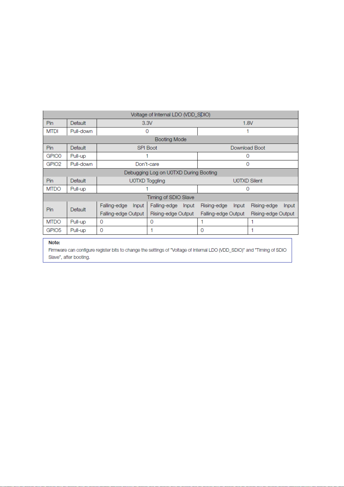
Refer to Table 3 for detailed boot modes’ configuration by strapping pins.
Table 3: Strapping Pins
Page 6
Page 7

www.Syrp.co.nz
3 functionalDescription
This chapter describes the modules integrated in ESP32-0037-7002, and their functions.
3.1 CPU and Internal Memory
ESP32 contains two low-power Xtensa® 32-bit LX6 microprocessors. The internal memory includes:
• 448 KB of ROM for booting and core functions.
• 520 KB (8 KB RTC FAST Memory included) of on-chip SRAM for data and instruction.
– 8 KB of SRAM in RTC, which is called RTC FAST Memory and can be used for data storage; it is
accessed by the main CPU during RTC Boot from the Deep-sleep mode.
• 8 KB of SRAM in RTC, which is called RTC SLOW Memory and can be accessed by the coprocessor during the Deep-sleep mode.
• 1 kbit of eFuse, of which 256 bits are used for the system (MAC address and chip configuration) and
the remaining 768 bits are reserved for customer applications, including Flash-Encryption and Chip-ID.
3.2 External Flash and SRAM
The ESP32-PICO-D4 module integrates 4 MB of external SPI flash. The 4-MB SPI flash can be
memory-mapped onto the CPU code space, supporting 8, 16 and 32-bit access. Code execution is
supported.
3.3 Crystal Oscillators
ESP32-PICO-D4 integrates a 40 MHz crystal oscillator.
3.4 RTC and Low-Power Management
With the use of advanced power-management technologies, ESP32 can switch between different
power modes (see Table 5).
• Power modes
– Active mode: The chip radio is powered on. The chip can receive, transmit, or listen.
– Modem-sleep mode: The CPU is operational and the clock is configurable. The Wi-
Fi/Bluetooth baseband and radio are disabled.
– Light-sleep mode: The CPU is paused. The RTC memory and RTC peripherals, as well as
the ULPcoprocessor are running. Any wake-up events (MAC, host, RTC timer, or external interrupts)
will wake up the chip.
– Deep-sleep mode: Only RTC memory and RTC peripherals are powered on. Wi-Fi and
Bluetooth connection data are stored in RTC memory. The ULP-coprocessor can work.
– Hibernation mode: The internal 8-MHz oscillator and ULP-coprocessor are disabled. The
RTC recovery memory is powered down. Only one RTC timer on the slow clock and some RTC
GPIOs are active. The RTC timer or the RTC GPIOs can wake up the chip from the Hibernation mode.
• Sleep Patterns
– Association sleep pattern: The power mode switches between the Active mode, Modem-
and Lightsleep mode, during this sleep pattern. The CPU, Wi-Fi, Bluetooth, and radio are woken up at
predetermined intervals to keep Wi-Fi/BT connections alive.
– ULP sensor-monitored pattern: The main CPU is in the Deep-sleep mode. The ULP-
coprocessor takes sensor measurements and wakes up the main system, based on the data collected
from sensors.
Page 7
Page 8

www.Syrp.co.nz
The power consumption varies with different power modes/sleep patterns and work statuses of
functional modules.Please see Table 6 for details.
Page 8
Page 9

www.Syrp.co.nz
4. Peripherals and Sensors
4.1 Peripherals and Sensors Description
Table 7: Peripherals and Sensors Description
Page 9
Page 10

www.Syrp.co.nz
Page 10
Page 11

www.Syrp.co.nz
Page 11
Page 12

www.Syrp.co.nz
Page 12
Page 13

www.Syrp.co.nz
Page 13
Page 14

www.Syrp.co.nz
5. Electrical Characteristics
Note: The specifications in this chapter have been tested under the following general condition: VDD = 3.3V, TA =
27°C, unless otherwise specified.
5.1 Absolute Maximum Ratings
Table 8: Absolute Maximum Ratings
5.2 Wi-Fi Radio
Table 9: Wi-Fi Radio Characteristics
Page 14
Page 15

www.Syrp.co.nz
5.3 BLE Radio
5.3.1 Receiver
Table 10: Receiver Characteristics – BLE
5.3.2 Transmitter
Table 11: Transmitter Characteristics – BLE
Page 15
Page 16

5.4 Reflow Profile
www.Syrp.co.nz
Page 16
Page 17

6. ESP32-PICO-D4 Schematics
www.Syrp.co.nz
Page 17
Figure 3: ESP32-PICO-D4 Schematics
Page 18

7. ESP32-0031-7002 Schematics
www.Syrp.co.nz
Page 18
Figure 4: ESP32-0031-7002 Schematics
Page 19

8. Peripheral Schematics
www.Syrp.co.nz
Page 19
Figure 4: ESP32-0031-7002 Peripheral Schematics
Page 20

www.Syrp.co.nz
9 Learning Resources
9.1 Must-Read Documents
The following link provides related documents of ESP32.
• ESP32 Datasheet
This document provides introduction to the specifications of the ESP32 hardware, including overview, pin
definitions, functional description, peripheral interface, electrical characteristics, etc.
• ESP32-PICO-D4 Datasheet
• ESP32 Technical Reference Manual
The manual provides detailed information on how to use the ESP32 memory and peripherals.
• ESP32 Hardware Resources
The zip files include the schematics, PCB layout, Gerber and BOM list of ESP32 modules and development
boards.
• ESP32 Hardware Design Guidelines
The guidelines outline recommended design practices when developing standalone or add-on systems
based on the ESP32 series of products, including ESP32, the ESP-WROOM-32 module, and ESP32DevKitC—the development board.
• ESP32 AT Instruction Set and Examples
This document introduces the ESP32 AT commands, explains how to use them and provides examples of
several common AT commands.
9.2 Must-Have Resources
Here are the ESP32-related must-have resources.
• ESP32 BBS
This is an Engineer-to-Engineer (E2E) Community for ESP32 where you can post questions, share knowledge,
explore ideas, and help solve problems with fellow engineers.
• ESP32 Github
ESP32 development projects are freely distributed under Espressif’s MIT license on Github. It is established
to help developers get started with ESP32 and foster innovation and the growth of general knowledge about
the hardware and software surrounding ESP32 devices.
• ESP32 Tools
This is a web-page where users can download ESP32 Flash Download Tools and the zip file ”ESP32 Certification
and Test”.
• ESP32 IDF
This web-page links users to the official IoT development framework for ESP32.
• ESP32 Resources
This webpage provides the links to all the available ESP32 documents, SDK and tools.
Page 20
Page 21

FCC Statement
This device complies with part 15 of the FCC Rules. Operation is subject to the following two
conditions: (1) This device may not cause harmful interference, and (2) this device must accept
any interference received, including interference that may cause undesired operation.
Any Changes or modifications not expressly approved by the party responsible for compliance
could void the user's authority to operate the equipment.
The modular can be installed or integrated in mobile or fix devices only. This modular cannot be
installed in any portable device.
FCC Radiation Exposure Statement
This modular complies with FCC RF radiation exposure limits set forth for an uncontrolled
environment. This transmitter must not be co-located or operating in conjunction with any other
antenna or transmitter. This modular must be installed and operated with a minimum distance
of 20 cm between the radiator and user body.
If the FCC identification number is not visible when the module is installed inside another device,
then the outside of the device into which the module is installed must also display a label
referring to the enclosed module. This exterior label can use wording such as the following:
“Contains Transmitter Module FCC ID: 2APDW0037 Or ContainsFCC ID: 2APDW0037”
When the module is installed inside another device, the user manual of the host must contain
below warning statements;
1. This device complies with Part 15 of the FCC Rules. Operation is subject to the following two
conditions:
(1) This device may not cause harmful interference.
(2) This device must accept any interference received, including interference that may cause
undesired operation.
2. Changes or modifications not expressly approved by the party responsible for compliance
could void the user's authority to operate the equipment.
The devices must be installed and used in strict accordance with the manufacturer's instructions
as described in the user documentation that comes with the product.
Any company of the host device which install this modular with Single modular approval should
perform the test of radiated emissionand spurious emission according to FCC part 15C : 15.247
requirement,Only if the test result comply with FCC part 15C : 15.247 requirement,then the host
can be sold legally.
Page 22

IC statement
This device complies with Industry Canada’s licence-exempt RSSs. Operation is subject to the
following two conditions:
(1) This device may not cause interference; and
(2) This device must accept any interference, including interference that may cause undesired
operation of the device.
Cet appareil est conforme aux CNR exemptes de licence d'Industrie Canada . Son fonctionnement
est soumis aux deux conditions suivantes :
( 1 ) Ce dispositif ne peut causer d'interférences ; etc
( 2 ) Ce dispositif doit accepter toute interférence , y compris les interférences qui peuvent
causer un mauvais fonctionnement de l'appareil.
A separation distance of at least 20 cm is maintained between the transmitter's radiating
structure(s) and the body of the user or nearby persons.
Une distance de séparation d'au moins 20 cm est maintenue entre l'émetteur rayonnant
structure (s) et le corps de l'utilisateur ou des personnes à proximité.
For a host manufacture's using a certified modular, if (1) the module's IC number is not visible
when installed in the host, or (2) if the host is marketed so that end users do not have
straightforward commonly used methods for access to remove the module so that the IC number
of the module is visible; then an additional permanent label referring to the enclosed module:
"Contains Transmitter Module IC: " 23768-0037" or "Contains IC: 23768-0037" must be used.
 Loading...