

Page 1
CONTROLS CONTROLS
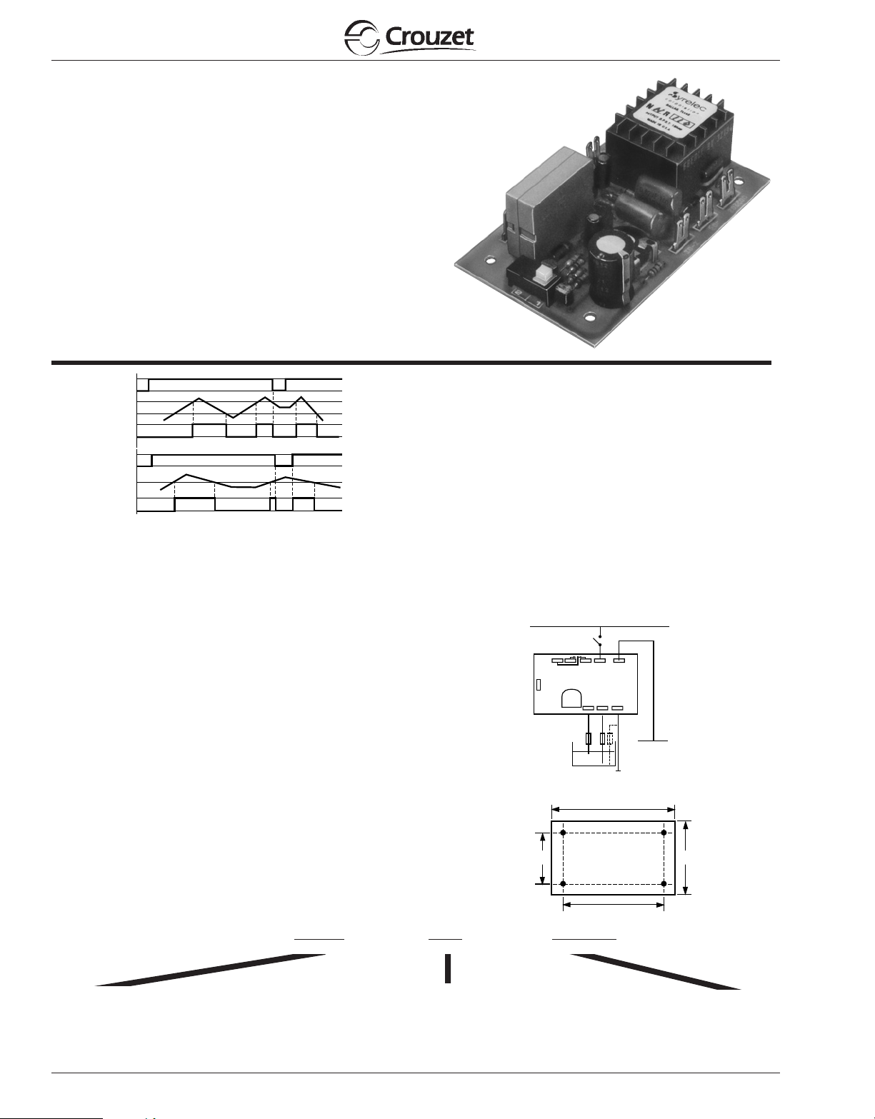
Pump Down (2)
Pump Up (1)
s
AC
AC
MinMax
Common
3
(76.2)
3.62
(92)
1.5
(38.1)
2.16
(55)
NNR SERIES
LIQUID LEVEL CONTROL
PUMP UP OR DOWN
SWITCH SELECTABLE
UL listed CSA recognized
• 10 Amp SPDT Rated
• Sensitivity Adjustment 4.7 kΩ to 47 kΩ
• One, Two or Three Probe Operation
• 24 VAC to 220 VAC Voltages
S
Max
min
LEVEL
R
S
LEVEL
R
t0
SPECIFICATIONS:
Input . . . . . . . . . . . . . . . . . . . . . . 24, 48, 110, 220 VAC
Maximum power consumption . . 24 VAC: 1.5 VA
Output . . . . . . . . . . . . . . . . . . . . . SPDT relay
Contact material . . . . . . . . . . . . . AgCdO (90/10)
Maximum loading . . . . . . . . . . . . 10 A AC resistive 1A DC inductive
Maximum switching voltage . . . . 250 VAC 30 VDC
Relay maximum power rating . . . 2500 VA 30 VDC
Mechanical life of relay . . . . . . . . 3 x 10⁷operations
Electrical life of relay . . . . . . . . . 2 x 10⁵at 2200 VA resistive load
Probe isolation . . . . . . . . . . . . . . . Switching contact: 2000 VA
Probe sensitivity . . . . . . . . . . . . . 4.7 K ohm to 47 K ohm
Probe voltage . . . . . . . . . . . . . . . 24 VAC, 60 Hz
Probe current . . . . . . . . . . . . . . . 2 mA max.
Operating temperature . . . . . . . . +14°F to 140°F -10°C to +60°C
Weight . . . . . . . . . . . . . . . . . . . . . 4.6 oz. (130g)
±15% (50/60 Hz)
48 VAC: 1.7 VA
110 VAC: 2 VA
220 VAC: 2 VA
Electrodes: 2000 VAC
A- Pump down function: the output relay energizes when the liquid level
reaches the high or max. probe. It remains energized until the level is
below the low or min probe. The relay will remain de-energized until the
high level is again reached. This control may also be used with only two
probes by connecting the maximum and common terminals together.
The output is energized when the low probe is in contact with the liquid.
B - Pump up function: when power is supplied to the unit, the output
relay is energized. When the level reaches the high probe the relay is
de-energized. The relay is energized again when the level falls below
the lob probe. The control may also be used with only two probes by
connecting the maximum and common terminals together. The output is
de-energized when the level reaches the low probe.
In both functions, If the container is conductive, It may be used as the
common probe in some applications
WIRING DIAGRAM:
DIMENSIONS:
Note: For best results use shielded cable with the probes and do not run probe
cables with other wires.
ORDERING INFORMATION:
N
MOUNTING
Products and specifications subject to change without notice.
N = Open PC Board
5-6
MOUNTING
NR
SERIES
SERIES
NR
220A
INPUT POWER
INPUT POWER
24A = 24 VAC
48A = 48 VAC
110A = 110 VAC
220A = 220 VAC
 Loading...