

Page 1
CONTROLS CONTROLS
Products and specifications subject to change without notice.
Order/Technical Support – Tel: (800) 677-5311 / FAX: (800) 677-3865 / www.crouzet-usa.com
2/88
IR.T SERIES
CURRENT CONTROL RELAY
UL listed CSA recognized
• Automatic or Manual Control
• Start-up Inhibit
• Adjustable Hysteresis
• Multiple Voltages
• LED Relay Status Indicator
SPECIFICATIONS:
Input . . . . . . . . . . . . . . . . . . . . . . . . 24 VDC, 24, 48, 110, 220 VAC
±15%, 50/60 Hz
Power consumption . . . . . . . . . . . 3 VA maximum
CONTROL RANGE PERMITTED OVERLOAD
DC AC INPUT LESS THAN
CURRENT CURRENT RESISTANCE PERMANENTLY 1 sec Peak
5 to 100 mA 3.5 to 70.7 mA 1 ohm 1.5 V 5 A
0.05 to 1 A 0.035 to 0.707 A 0.1 ohm 5 A 17 A
0.5 to 10 A 0.35 to 7.07 A 0.01 ohm 15 A 55 A
Hysteresis selection . . . . . . . . . . . 5 to 50% of input current
Repeat accuracy . . . . . . . . . . . . . . ±2% at a constant ambient
Response time . . . . . . . . . . . . . . . . 100 ms On Make
200 ms On Break
Output Relay . . . . . . . . . . . . . . . . . SPDT Relay
Contact material . . . . . . . . . . . . . . AgCdO
Maximum loading . . . . . . . . . . . . . 10 A AC resistive 1 A DC inductive
Maximum switching voltage . . . . . 250 VAC or DC
Relay maximum power rating . . . . 2500 VA 30W
Mechanical life of relay . . . . . . . . . 30 x 104operations
Electrical life of relay . . . . . . . . . . . 2 x 10⁵at 2500 VA resistive load
Operating temperature . . . . . . . . . +14°F to + 140°F -10°C to +60°C
Weight . . . . . . . . . . . . . . . . . . . . . . 7 oz. (200g)
Option: 24 VDC power - the voltage and the measured current must be
from separate sources.
Note: It is recommended that the unit be adequately fused.
MOUNTING
D = DIN-rail mounting
L = 11 pin plug-in
SERIES
IR.T
L
MOUNTING
IR.T
SERIES
110A
INPUT POWER
INPUT POWER
24D = 24VDC
24A = 24VAC
48A = 48VAC
110A = 110VAC
220A = 220VAC
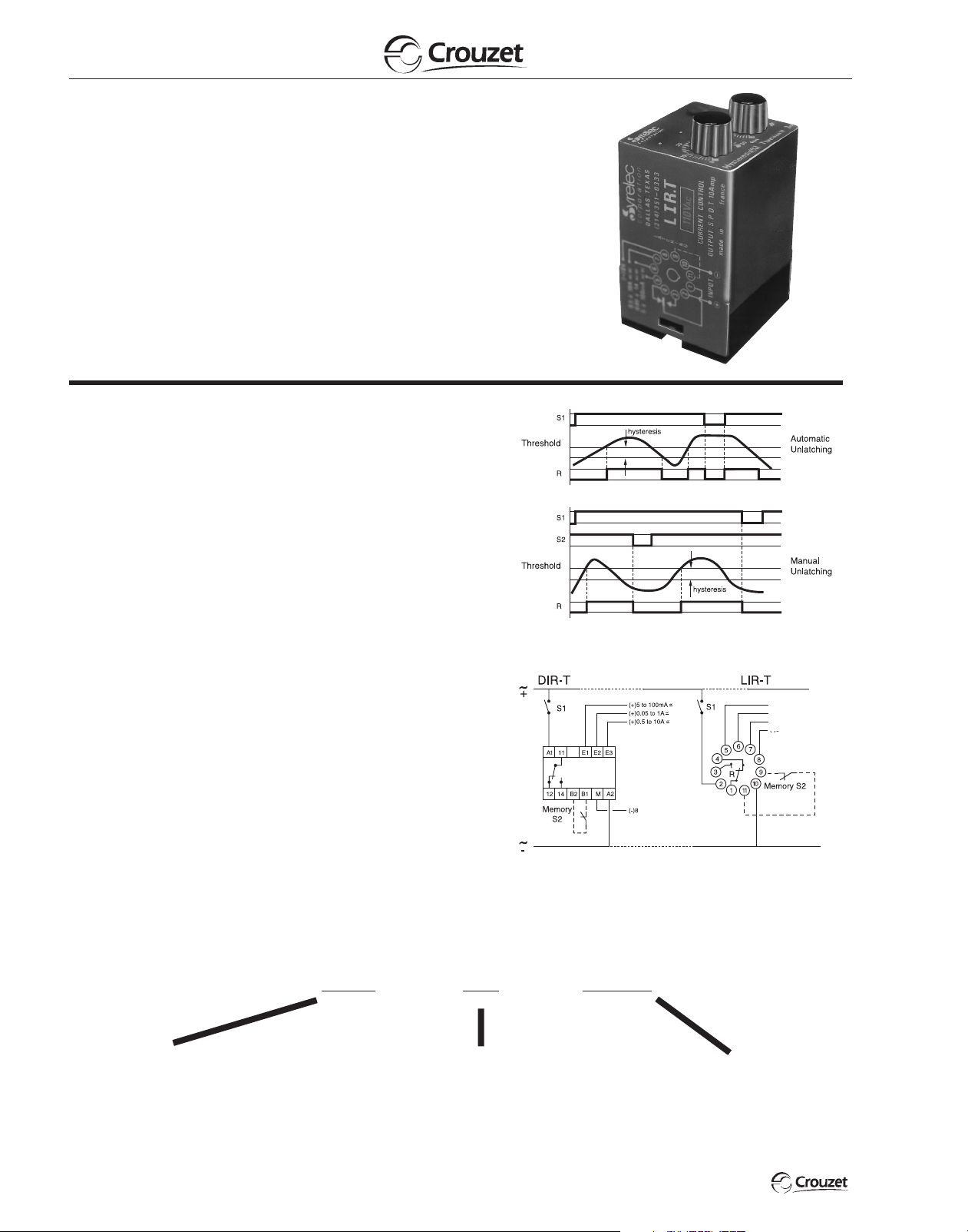
WIRING DIAGRAM:
ORDERING INFORMATION:
1. AC Current Control Without Latching:
The output relay is energized when the current (peak current on AC) overshoots the level selected on the potentiometer. It de-energizes when the
current falls below the normal current by 5 to 50% or when input power
breaks. The hysteresis is controlled by a top mounted potentiometer and
its selection does not change the chosen current level.
2. AC Current Control With Latching:
The output relay is energized when the current reaches the selected value
and stays latched. The contact between terminal B1 and B2 (or 11 and 9)
should be opened or input power to the device interrupted to reset. In this
case, it is preferable to reduce the hysteresis 5%.
Note: Upon energization of the current control IR.T Series Relay,
the time delay, which is adjustable from .1 to 10 seconds, inhibits
the output relay during start-up periods. The delay time is adjustable
via a potentiometer located on the side of the case. Applies to both
versions, with and without latching.
0V
0V
(+)5 to 100mA
~
(+)0.05 to 1A
~
(+)0.5 to 10A
~
(–)0V
–
–
–
 Loading...