


Instructions of use

2
1. Field of application
The SYR-Safe-T is an effective anti-leakage
system in compliance with recognized
international standards. It is adaptable to all
SYR anges from DN 20 to DN 32.
Fully automatic electronic anti-leakage system
with contacts for many different connection possibilities.
With two O-rings, a seal, small hexagonal socket screws for the installation, a mounting key
and a oor sensor.
2. Model
3. Inserting / Exchanging
batteries
Insert the batteries prior to using the Safe-T.
Open the upper battery door and remove the
battery block.
Table of contents
1. Field of application ................................... 2
2. Model ....................................................... 2
3. Inserting / Exchanging batteries ............... 2
3.1 Initial operation ................................ 3
4. General operation .................................... 3
4.1 Unlocking the keyboard ................... 3
5. User menu ................................................ 4
5.1 Leakage protection .......................... 4
5.2 Setting the leakage protection ......... 4
5.3 Deactivating the leak. protection ..... 5
5.4 Vacation leakage protection ............ 5
5.5 Setting the vacation leakage
protection ........................................ 6
5.6 Deactivating the vacation leakage
protection ........................................ 6
5.7 Stop valve ....................................... 7
5.8 Changing the stop valve‘s status .... 7
5.9 Re-opening the stop valve after
leakage ............................................ 7
6. Other settings ........................................... 8
6.1 48h-leakage .................................... 8
6.2 Changing the 48h-leakage mode .... 8
6.3 Time-based leakage (volume) ......... 8
6.4 Time-based leakage (ow rate) ....... 9
6.5 Unlocking the device ....................... 9
6.6 External alarm contact .................... 9
6.7 Buzzer ........................................... 10
6.8 Contact 1 ....................................... 10
6.9 Contact 2 ....................................... 10
6.10 Mounting conditions ...................... 11
7. System information ................................ 11
7.1 Serial number ................................ 11
7.2 Battery power ................................ 11
7.3 Alarm memory ............................... 12
8. Emergency unlock function .................... 12
8.1 Restart ........................................... 13
9. Technical specications .......................... 14
10. Connections ........................................... 14
11. Accessories ............................................ 14
12. Dimensions ............................................ 15
13. Messages ............................................... 16
Insert the battery block or exchange it (4 x LR
06) and put it back into place in the battery compartment.
Warning: The batteries have to be inserted even when using the mains plug!

Symbol Key Meaning
Mode To validate entries
Down To decrease values
Up To increase values
3
Exchange the batteries every two years at
the latest!
Do not use accumulators!
3.1 Initial operation
As soon as the batteries are inserted, the
system rst goes into the closed position.
The display shows the message IO.
When pressing the
- key, the system goes
into the open position.
The system is open when the message 10
ashes in the display. Afterwards, it goes into
the normal operation mode.
Make sure that the battery block is correctly positioned in the compartment against the internal
back wall.
Close the battery door.
As an option, you can also connect the SYR
Safe-T with a mains plug (1100.00.900).
4. General operation
The display consists of two digits and three
press buttons (mode, down and up key).
Use the
or key to adjust the various values.
Use the key to conrm and save the values or
to activate another menu.
4.1 Unlocking the keyboard
When the Safe-T is exclusively batteryoperated, press any key to activate the display.
It will automatically disconnect after 30 seconds.
The device‘s keyboard is locked.

4
5.2 Setting the leakage
protection
When pressing the key, the menu for the vacation leakage protection appears in the display,
provided it is activated.
When pressing the key again, the current
anti-leakage setting is displayed.
When no key is activated within 30 seconds,
the display goes back into the locked position.
5.1 Leakage protection
Unlock the keyboard to change values.
Press simultaneously the and key for
about 3 seconds. The display starts ashing to
signal that the keyboard is unlocked.
5. User menu
When the device is mains-operated, the
display always remains active.
The leakage mode provides for a standard
supervision of the installation.
The system calculates the volume own without
interruption as well as the ow rate.
Should one of the following criteria be exceeded,
the device suspects a leakage problem and
closes the main isolating valve.
• In case the water quantity own without
interruption exceeds the set limit for the
volume-based leakage (100 - 1500 liters) →
Message A3 is displayed.
• In case the ow rate exceeds 3500l/h for one
minute → Message A4 is displayed.
• In case of an uninterrupted ow of water
during 2 hours with a setting of 100 to 400
liters → Message A9 is displayed.
• In case of an uninterrupted ow of water
during 3 hours with a setting of 500 to 700
liters → Message A9 is displayed.
• In case of an uninterrupted ow of water
during 4 hours with a setting of 800 to 1100
liters → Message A9 is displayed.
• In case of an uninterrupted ow of water
during 5 hours with a setting of 1200 to 1500
liters → Message A9 is displayed.
Unlock the keyboard, if needed.
The message „LE“ ashes in the display.
When pressing the
key again, the menu for
the leakage protection displayed.

Menu Values
Leakage protection (LE)
--
(deactivated)
1 - 15 (100 - 1500
liters)
(Factory set to: 4)
Vacation leakage
protection (UL)
--
(deactivated)
1 - 10 (10 - 100 liters)
Factory set to: 10
Stop valve
(AB)
P1 (OPEN), P2 (CLOSED)
Factory setting:
P1 (OPEN)
5
5.3 Deactivating the leakage
protection
To deactivate the leakage protection, unlock the
keyboard, if necessary.
Press the key until reaching the menu „LE“.
Set the desired value by means of the or
key.
The system allows for the following settings:
Press the
key to validate and save the
changes.
Press the
key to display the current setting.
Set the desired value by means of the
- or
key.
Press the
key to save the settings.
Note: The leakage protection system is
automatically reactivated after 8 hours!
Should a tighter supervision be needed for a
certain time, use the vacation leakage protection
mode.
This setting implies that only minor water
quantities between 10 and 100 liters will be
drawn off without interruption.
When the indicated water quantity is exceeded,
a leakage problem is suspected → Message A5
is displayed.
5.4 Vacation leakage
protection

6
In order to change the setting of the vacation
leakage protection, unlock the keyboard, if
necessary.
Press the
key until reaching the „UL“ menu.
5.5 Setting the vacation
leakage protection
Press the key to save the settings.
Press the
key again to display the current
setting of the vacation leakage protection.
Press the
key until the vacation leakage
protection is displayed.
5.6 Deactivating the vacation
leakage protection
In order to deactivate the leakage protection, set
the desired value by means of the or key.
Press the key to save the settings.
Set the desired value by means of the
or
key.

7
I
nformation: When the SYR Safe-T has
recognized a volume-based leakage, it
closes the installation and opens it again
after 30 seconds, in order to check whether
more water is being drawn off.
If this is not the case, the Safe-T remains
open and allows for more water to be drawn
off up to the set volume.
Press the
key again to display the current sta-
tus of the leakage protection‘s stop valve.
Press the
key to display the menu of the lea-
kage protection‘s stop valve.
5.7 Stop valve
In order to change the stop valve‘s position, unlock the keyboard, if necessary.
Set the desired position by means of the or
key.
Press the
key to save the settings.
5.8 Changing the stop valve‘s
position
5.9 Re-opening the stop
valve after leakage
When the SYR Safe-T has isolated the
installation after having recognized a leakage
problem, it can be re-opened by pressing the
key.

8
6. Other settings
In order to get into the menu for other settings,
press the key and simultaneously three times
the key.
Unlock the keyboard (4.1, page 3) if necessary,
prior to changing the values.
6.1 48 hours - anti-leakage
system
Indicate whether the 48 hours anti-leakage
system shall be activated or deactivated.
Set the desired status by means of the
or
key and save the change with the key.
6.3 Time-based leakage
(volume)
Press the key again and use the or key
to adjust the number of hours after which the ow
of water (1-9) has to be stopped, or to deactivate
this function.
This setting is deactivated in the standard setting.
Press the key until the menu of the time-based leakage (volume) is displayed.
Save the change by pressing the key.
In order to also ensure a sufcient leakage
protection in case of a longer absence without
having activated the vacation supervision, use
the following function:
When no water is drawn off during 48 hours,
the main stop valve isolates the system for 3
minutes.
When the stop valve opens again after 3
minutes, the device veries whether water
continues to ow.
If the ow of water exceeds 250 ml, a leakage
problem is suspected → Message A8 is
displayed.
The 48 hours anti-leakage system is deactivated
in the standard setting.
6.2 Activating /deactivating
the 48 h-anti-leakage system
When the time-based leakage protection is
activated, the time set for the standard leakage
supervision is deactivated and replaced by this
time-based protection.
The set volume is not taken into consideration.
Example: When selecting the 600 liters setting,
a leakage problem would be suspected after 3
hours, even if the 600 liters volume has not been
reached.
However, if the time-based leakage supervision
is set to 8 hours, a leakage problem is only
suspected after 8 hours.
In this case, the maximum ow rate shall not
exceed 75 l (600 liters / 8 hours = 75 liters / h) →
Message A9 is displayed.

Value Meaning Symbol
Contact is deactivated
Closing contact
Opening contact
Impulse contact
9
6.4 Time-based leakage
(ow rate)
Press the key until the time-based leakage
(ow rate) menu is displayed.
If the ow rate exceeds 3500 l/h, a leakage
problem is supected → Message
A4 is displayed.
The standard value of 1 minute can be changed
with this parameter.
When the ow rate remains under 3500 l/h before
the time has expired, the time is reset.
When the ow rate has been exceeded, the time
starts again.
Press the key again and use the or key
to set how long (number of minutes) the device
shall wait before closing the water supply when
the ow rate exceeds 3500 l/h.
Save the change by pressing the
key.
6.5 Unlocking the device
The next step leads to the menu allowing to unlock the device.
When the SYR Safe-T has isolated the system
after an unintended volume-based leakage,
the device allows to determine whether it shall
re-open after 30 seconds without water being
drawn off.
Press the or key to activate or deactivate
the function.
Press the
key to save the change.
This parameter cannot be switched off or
reset to „0“.
6.6 External alarm
contact
The menu offers settings for a potential free
contact.
This contact offers various possibilities to display or signal an alarm.
Use the
or key to set how the Safe-T‘s
alarm contact is to be programmed.
Save the change by pressing the key.
This function is only available in conjunction with
the mains plug.

Value Meaning
Contact is deactivated
Value Meaning Closed Open
Impulse
Opening
contact
Closing
contact
key
key
key
10
6.7 Buzzer
The menu Buzzer allows to select an acoustic
signal in addition to the displayed message.
Set the desired status by means of the
or
key and save the change by pressing the key.
6.8 Contact 1
You can register a connected oor sensor in the
Safe-T‘s menu contact 1.
This function is only available in conjunction with
the mains plug.
Set the desired status by means of the
or
key and save the change by pressing the key.
6.9 Contact 2
The contact 2 offers many connection
possibilities.
You can connect for instance oor sensors or
temperature probes.
The Safe-T can also be actuated via switchbuttons, phone impulses, timers, radiocontrolled oor sensors etc.
The system allows for the following settings:
The positions 1 to 3 offer various contact
possibilities able to isolate the installation.
With these settings, press the
key after a
signal to unlock the device again.
Caution: The plug has to be fully inserted
into the socket!
A plausibility test is carried out and a message is
displayed after at least one minute.

Value Meaning Closed Open
Impulse
Opening
contact
Closing
contact
11
The positions 4 to 6 also offer various contact
possibilities able to isolate the installation.
With these settings, the device waits for a signal
from outside to unlock again.
Pressing the
key is not required as the
opening process runs automatically once the
signal is given.
This function is only availble in conjunction with
the mains plug.
6.10 Mounting conditions
Finally, you can select whether the Safe-T shall
supervise the installation with full (Hc) or restricted (only oor sensor) (Hd) supervision.
Save the change by pressing the
key.
Press the
or key to dene the conditions.
When selecting the restricted supervision,
the leakage potection is only ensured by
the oor sensor.
All other supervising functions are
deactivated!
7. System information
Press the key and once the key at the
same time in order to get into the menu for the
system information.
7.1 Serial number
The menu allowing to read the serial number is
displayed.
N
ote: This level only allows reading
data. They cannot be changed.
Press the
key to display the serial number.
Press the
key to continue.
Example of installation in an apartment house:

12
Press the
key to display the battery power.
Press the
key to continue.
7.3 Alarm memory
The SYR Safe-T has 8 memory spaces designed to save alarm messages.
Press the key several times to read these
messages.
When no message has been saved yet, the
following appears in the display:
8. Emergency unlock
function
The emergency unlock function is designed to
unlock the system manually in case the SYR
Safe-T isolates the installation and a power failure occurs at the same time.
The emergency unlock function is located on the
back side of the leakage protection module.
Remove the two cover parts sideways.
The key for the manual opening is located on
the inner side of the left cover.
7.2 Battery power
The menu for the battery power is displayed.

13
Remove the clamp from the control unit so that
it can be lifted and taken off.
Put the key in the required position and turn it
in the direction of the arrow until the water ows
again.
Remove the key and follow the instructions to
restart the device (8.1, page 11).
Mount the control unit and secure it with the
clamp.
Put the two insulating covers back into place.
As the position has been changed manually
with the emergency unlock function, the SYR
Safe-T should be restarted.
Unlock the keyboard.
Press the
key until reaching the menu „AB“.
8.1 Restart
Press the or key to set the status „P1“.
Caution: Do not t the control unit on the
Safe-T to restart the system!

DN 20 DN 25 DN 32
Dp 0.2 bar 2.0 m³/h 2.3 m³/h 2.5 m³/h
Dp 0.5 bar 3.5 m³/h 3.8 m³/h 4.0 m³/h
Dp 1.0 bar 5.2 m³/h 5.7 m³/h 6.0 m³/h
14
9. Technical specications
Service temperature: max. 30°C
Ambient temperature: 10 - 60°C
Nominal pressure: 16 bar
Type of protection: IP 21
Batteries: 4 x LR06
Power mains plug: 9V DC
Max. load of external
potential free contact
IN2: min. 12V / 20mA
Out: max. 24V / 2A
Flow rate:
10. Connections
OUT Relais output
IN2 external contact
Mains 9V DC
IN1 Floor sensor
Only qualied installers are authorised
to install and service the device. Do not
clean synthetic parts with solvent-based
detergents. Protect the device and the
electronic system against frost. When
submitted to hard shocks, the synthetic part concerned shall be exchanged
(even when no damages are visible).
Avoid strong water hammers caused for
instance by downstream solenoid valves
(danger of burst).
The packaging serves as transport protection. Should it be severely damaged,
do not install the device!
The device is now ready for operation.
Press the
key to save the settings.
More information available under
export@syr.de
11. Accessories
Mains power adapter: 1100.00.900
Plug: 2320.00.901
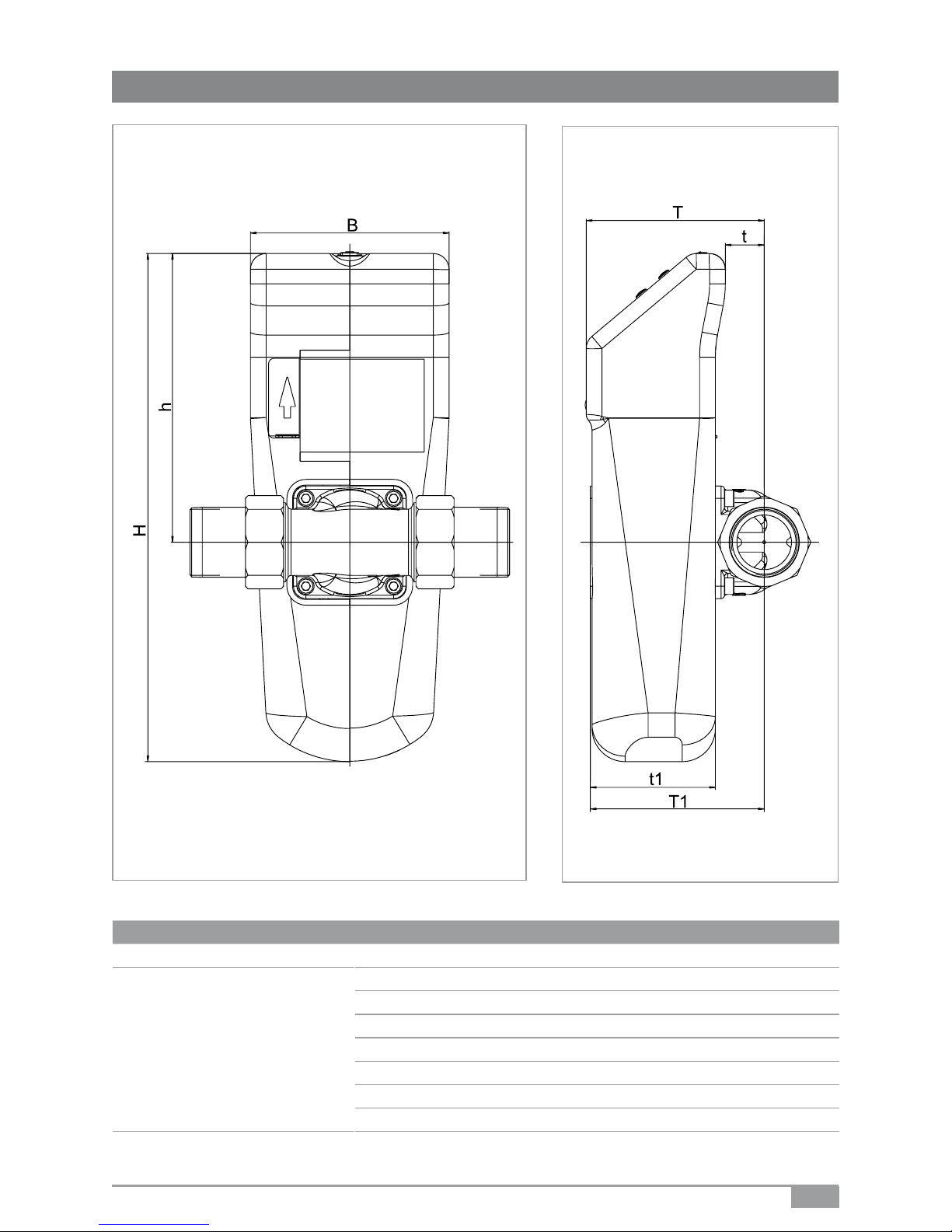
Type SYR Safe-T Leakage protection module
Nominal size DN 20 - 32
Dimensions
T 108 (mm)
t 24 (mm)
T1 105 (mm)
t1 76 (mm)
H 307 (mm)
h 174 (mm)
B 120 (mm)
15
12. Dimensions
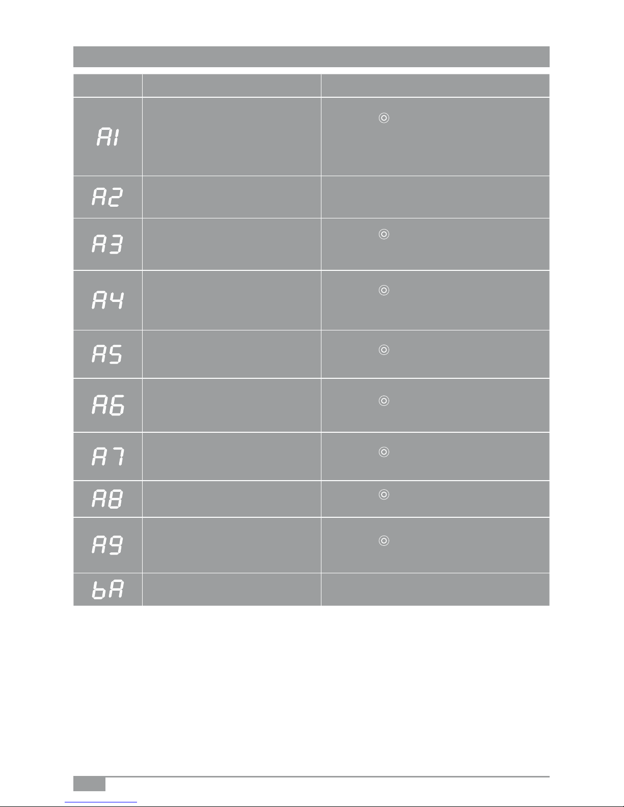
Display Cause Solution
- The stop valve cannot be operated.
Probably caused by dirt.
- Defective motor.
- Press the
key. The system tries again to reach
the position.
- Contact your local dealer.
- The turbine is blocked. - Contact your local dealer.
- A volume-based leakage problem
has been identied. The set or
admissible volume ow has been
exceeded.
- Press the
key to open the stop valve. Adjust
the protection level and eliminate the leakage
problem.
- A contineous volume ow
> 3500l/h within one minute has been
identied (for instance burst pipes).
- Press the
key to open the stop valve. Adjust
the protection level and eliminate the leakage
problem.
- The system has identied a vacation
leakage problem. The set or admissible volume ow has been exceeded.
- Press the
key to open the stop valve and
eliminate the leakage problem.
- The system has identied a leakage
problem at contact IN1 (oor sensor).
- Press the
key to open the stop valve and
eliminate the leakage problem.
- The system has identied a leakage
problem at contact IN2.
- Press the
key to open the stop valve and
eliminate the leakage problem.
- A 48h - leakage problem (for instance
toilet ush) has been identied.
- Press the
key to open the stop valve and
eliminate the leakage problem.
- The ow rate time criterion has been
exceeded. The set or admissible ow
time has been exceeded.
- Press the
key to open the stop valve and
eliminate the leakage problem.
- The batteries are empty. - Replace the batteries (4 x LR06).
16
13. Messages
printed in Germany - 9.2421.07 1050 - Subject to alteration
Hans Sasserath & Co. KG • Tel.: +49 2161 6105-0 • Fax: +49 2161 6105-20
Mühlenstraße 62 • D-41352 Korschenbroich • info@SYR.de • www.SYR.de
 Loading...