

Page 1
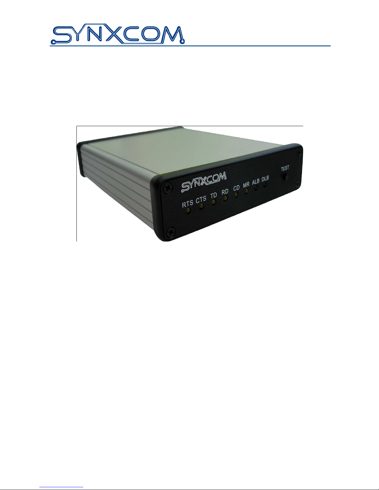
User’s Manual
For Models
SM19202FP, SM19202FP-K
SM96202FP, SM96202FP-K
Fast Poll Modems
Document Number 520-01014-001 Rev. C
Page 2

Copyright © 2012 Synxcom, Incorporated.
All Rights Reserved.
Web site: www.synxcom.com
The products and programs described in this User’s Manual are licensed products of Synxcom Inc.
This User’s Manual contains proprietary information protected by copyright, and this User’s Guide and
all accompanying hardware and documentation are copyrighted.
Synxcom Inc. does not warrant that the product will work in all environments and applications, and
makes no warranty and representation, either implied or expressed, with respect to the quality,
performance, merchantability, or fitness for a particular purpose.
Information in this User’s Guide is subject to change without notice and does not represent a
commitment on the part of Synxcom Inc. Synxcom Inc. assumes no responsibility for any
inaccuracies that may be contained in this User’s Manual.
No part of this manual may be reproduced or transmitted in any form or by any means, electronic or
mechanical, including photocopying, recording, or information storage and retrieval systems, for any
purpose other than the purchaser's personal use, without the express written permission of Synxcom
Inc.
How to obtain Technical Supports
e-mail: [email protected]
Phone: (949) 390-8236
Fax : (949) 872-2889
Technical Support is available from 8:00 am to 5:00 pm PST, weekdays except major holidays.
e-mail support is 7-day a week excluding major holidays.
SM19202FP Fast Poll Modem User’s Manual
520-01014-001 Rev. C
March 15, 2012
Page 3

Contents
Chapter 1 Introduction ............................................................................................ 6
Features .................................................................................................................... 7
Applications ............................................................................................................... 8
Chapter 2 Installation .............................................................................................. 9
Unpacking Your Hardware ......................................................................................... 9
Additional Items You Need to Complete Your Installation .......................................... 9
Hardware Overview ................................................................................................. 10
Front View ............................................................................................................... 10
Back View ................................................................................................................ 10
Rack-Mount View..................................................................................................... 11
Installation Summary ............................................................................................... 11
Configuring the Stand-alone Modem........................................................................ 12
Setting the DIP Switches ......................................................................................... 14
S1-1, S1-2, S1-3 − Modem Data Rate ................................................................ 15
S1-4 − Async Character (Fast-Poll Mode Only) .................................................. 16
S1-5 − Auto RTS ................................................................................................ 16
S1-6 − Transmit Carrier Control (For SM19202FP-K only) ............................... 16
S1-7 − 2-/4-Wire Leased Line Operation ............................................................ 17
S1-8 − Transmitter Impedance ........................................................................... 17
S1-9 − Remote Loopback Enable ...................................................................... 18
S1-10 − Reserved (Test Only) ............................................................................ 18
S2-1 through S2-3 − Transmit Level................................................................... 18
S2-4 − Receiver Dynamic Range ....................................................................... 19
S2-5 and S2-6 − Cable Equalizer (Fast-Poll Mode Only) .................................... 19
S2-7 − Anti-streaming ........................................................................................ 19
S2-8 − RTS-CTS Delay (Bell 202 Mode Only) .................................................... 19
S2- 9− Forced RTS ON (Constant RTS) ........................................................... 20
S2- 10− Re-Train Request Enabled ......................................................................... 20
S3- 1 and S3-2− RS-232 or RS-485 Interface Select .............................................. 20
S3-3 RS-485 Receiver Termination ........................................................................ 21
S3-4- Not Used .................................................................................................. 21
S-3-5 Leased Line Receiver Termination ........................................................... 21
S3-6- Common Signal Ground and Chassis Ground ......................................... 21
Configuring the Jumper Blocks ................................................................................ 21
For Stand-alone Units ........................................................................................ 21
For Rack-Mount Plug-in Modules ....................................................................... 21
iii User’s Manual - SM19202 Fast Poll Modem
Page 4

Contents
Connecting to a Transmission Line .......................................................................... 22
Connecting to a Voltage Source .............................................................................. 23
Connecting to an RS-232 Device ............................................................................. 24
Connecting to an RS-485 Device ............................................................................. 24
LEDs........................................................................................................................ 26
Loopback Control Switch ......................................................................................... 26
Appendix A Troubleshooting................................................................................ 28
Problem Solving ...................................................................................................... 28
Appendix B Specifications ................................................................................... 29
General Specifications ............................................................................................. 29
Mechanical Specifications ........................................................................................ 30
Interface Connector Pin Assignments ...................................................................... 30
RS-232 (DTE) Interface ........................................................................................... 31
RS-485 (DTE) Interface ........................................................................................... 31
Environmental Specifications ................................................................................... 31
Appendix C Limited Product Warranty ................................................................ 32
Appendix D RMA Procedure ................................................................................. 33
iv User’s Manual - SM19202 Fast Poll Modem
Page 5

Contents
Figures
Figure 1-1. Point-to-Point Network Using the SM19202FP Modem ....................................... 8
Figure 1-2. Multipoint Polling Network Using the SM19202FP Modem .................................. 8
Figure 2-1. Front View of the SM19202FP Modem .............................................................. 10
Figure 2-2. Back View of SM19202FP Modem .................................................................... 10
Figure 2-3. Rack-Mount Module for the SM19202FP-RM Modem Board ............................. 11
Figure 2-4. SM19202 Fast-Poll Stand-alone Modem Switches ............................................ 13
Figure 2-5. SM19202 Fast-Poll Rack-mount Modem Board ................................................. 14
Figure 2-6. SM19202FP Modem Transmission Line Interface ............................................. 22
Figure 2-7. Pin Locations on the Modem’s RJ-11C Jack ..................................................... 24
Figure 2-8. Loopback Diagnostic Modes ............................................................................. 27
Figure 2-9. Back-to-Back Connection to a Second Modem ................................................. 30
Tables
Table 2-1. Modem Switch Settings ...................................................................................... 14
Table 2-2. Modem Operating Speed ................................................................................... 16
Table 2-3. Transmit Levels .................................................................................................. 18
Table 2-4. Transmission Line Connector Pin Assignments .................................................. 22
Table 2-5. RJ-11C Modular Jack Pin Assignments .............................................................. 24
Table 2-6. Modem LEDs ..................................................................................................... 26
Table A-1 Problem Solving ................................................................................................. 28
Table B-1. Leased Line Terminal Block Pin Assignments .................................................... 30
Table B-2. RS-232 (DTE) Interface ..................................................................................... 31
Table B-3. RS-485 (DTE) Interface ..................................................................................... 31
v User’s Manual - SM19202 Fast Poll Modem
Page 6

Chapter 1
Introduction
Thank you for purchasing Synxcom’s SM19202FP fast poll modem, the finest industrialgrade fast-poll modem available.
The Synxcom modem is a 19200/9600/4800/2400/1200 bps modem designed for 4-wire,
full-duplex or 2-wire, half-duplex operation over a voice-band leased line or private line. The
modem is designed utilizing the latest digital-signal processing (DSP) technology to achieve
high performance. The modem employs efficient modulation and encoding scheme to
achieve fast modem training time. The modem is also backward compatible with Bell 202
and ITU-T V.23 modems.
The SM19202FP is the most technologically advanced modem on the market. Boasting a
fast DSP processor and automatic adaptive equalizer, the SM19202FP modem is ideally
suited for multi-point communication systems that require fast response time, short training
time, and low throughput delay.
This User’s Guide describes the SM19202FP (AC-powered) and SM19202FP-DC (DCpowered) stand-alone modems, as well as the rack-mount SM19202FP-RM plug-in module
for the Motorola/UDS RM16M. This manual is designed to get your modem “up and running”
as quickly as possible. It contains all the information you need to configure and install your
modem. It also contains troubleshooting information in the unlikely event you encounter a
problem with your modem.
6 User’s Manual - SM19202 Fast Poll Modem
Page 7

Introduction
Features
The SM19202FP modem is specifically designed for harsh environments typically
associated in utility substations and industrial facilities. Though functionally similar to
commercial modems, the SM19202FP provides the following unique features that make it
well suited for utility and industrial applications.
Packaged in a rugged, compact enclosure for industrial applications.
Leased-line interface protected with heavy-duty surge protection devices.
Built-in hardware watchdog timer for software lock-up prevention without requiring
human intervention, making it ideal for unmanned locations.
Works within an extended temperature range of -40ºC to +85ºC.
Designed with coupling transformers for high-voltage isolation and common mode
noise rejection in industrial and commercial environments.
Operate over voice-band conditioned or unconditioned leased-line and pilot wires.
Accepts power from a wide range of AC and DC power supplies:
– SM19202FP: 90 to 265 VAC or 100 to 400 VDC
– SM19202FP-DC: 10 to 60 VDC
– SM19202FP-RM: Plug-in module for the Motorola/UDS RM16M modem nest
Standard industrial connectors for data, analog, and power interfaces allow reliable
interconnection to other industrial equipment.
Asynchronous data rates (selectable) of 19200, 9600, 4800, 2400, and 0-1800
bps.
Easily accessible DIP switches for user configuration and option selection.
DB9-F connector for RS-232/V.24 interface, and RJ-11 for RS-485.
Local analog, local digital, and remote digital loopback diagnostics.
7 User’s Manual - SM19202 Fast Poll Modem
Page 8
Introduction
Applications
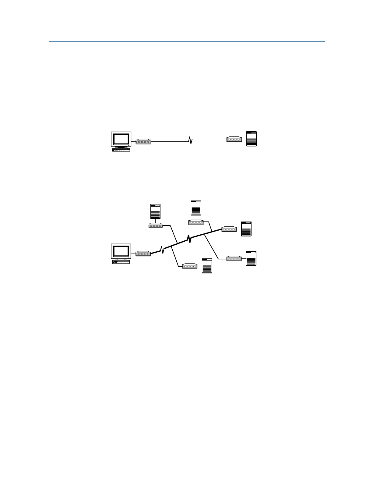
The SM19202FP modem is designed for point-to-point and multipoint data communications.
Figure 1-1 shows a typical point-to-point configuration using the SM19202FP modem and
Figure 1-2 shows a typical multipoint configuration using the SM19202FP modem.
Modem
Workstation
Modem
Remote Terminal
Figure 1-1. Point-to-Point Network Using the SM19202FP Modem
Modem
Modem
Workstation
Modem
Modem
Modem
Remote Terminal
Modem
Remote Terminal
Figure 1-2. Multipoint Polling Network Using the SM19202FP Modem
There are a number of factors that can affect the modem’s operation and performance.
These include:
Modem speed (i.e. bit error rate, transmission line distance)
2-wire or 4-wire configuration
Transmission line characteristics, noise, and line impairments
Network configuration (point-to-point or multipoint)
8 User’s Manual - SM19202 Fast Poll Modem
Page 9

Chapter 2
Installation
This chapter describes how to configure and install the modem to maximize the performance
and to match with your Data Terminal Equipment (DTE) or Remote Terminal Unit (RTU).
Unpacking Your Hardware
Your package should include:
At least one of the following SM19202FP modems:
– Model SM19202FP for 90 to 265 VAC
– Model SM19202FP-DC for 10 to 60 VDC
– Model SM19202FP-RM for RM16M plug-in module
A switching power supply module for 90-265VAC input (model SM19202FP only)
A leased-line cable with optional earth ground conductor (for stand-alone units
only)
A DC power cable (model SM19202FP-DC modem only)
This User’s Manual or CD-ROM
If your package contents are damaged or missing, contact your place of purchase.
Additional Items You Need to Complete Your Installation
To complete your installation and operate your modem, you need these additional items:
Two- or four-wire transmission line or leased line
A DB-9 data cable for your RS-232 interface Data Terminal Equipment (DTE) port,
or a RJ-11C data cable for your RS-485 DTE.
Power supply that provides either:
– 90 to 265 Volts AC, 50 to 60 Hz, single phase or 100 to 400 VDC (if you have
the model SM19202FP modem), or
– 10 to 60 Volts DC (if you have the model SM19202FP-DC modem)
– For the SM19202FP-RM, consult the documentation for your Motorola/UDS
RM16M
9 User’s Manual - SM19202 Fast Poll Modem
Page 10
Installation
Hardware Overview
Front View
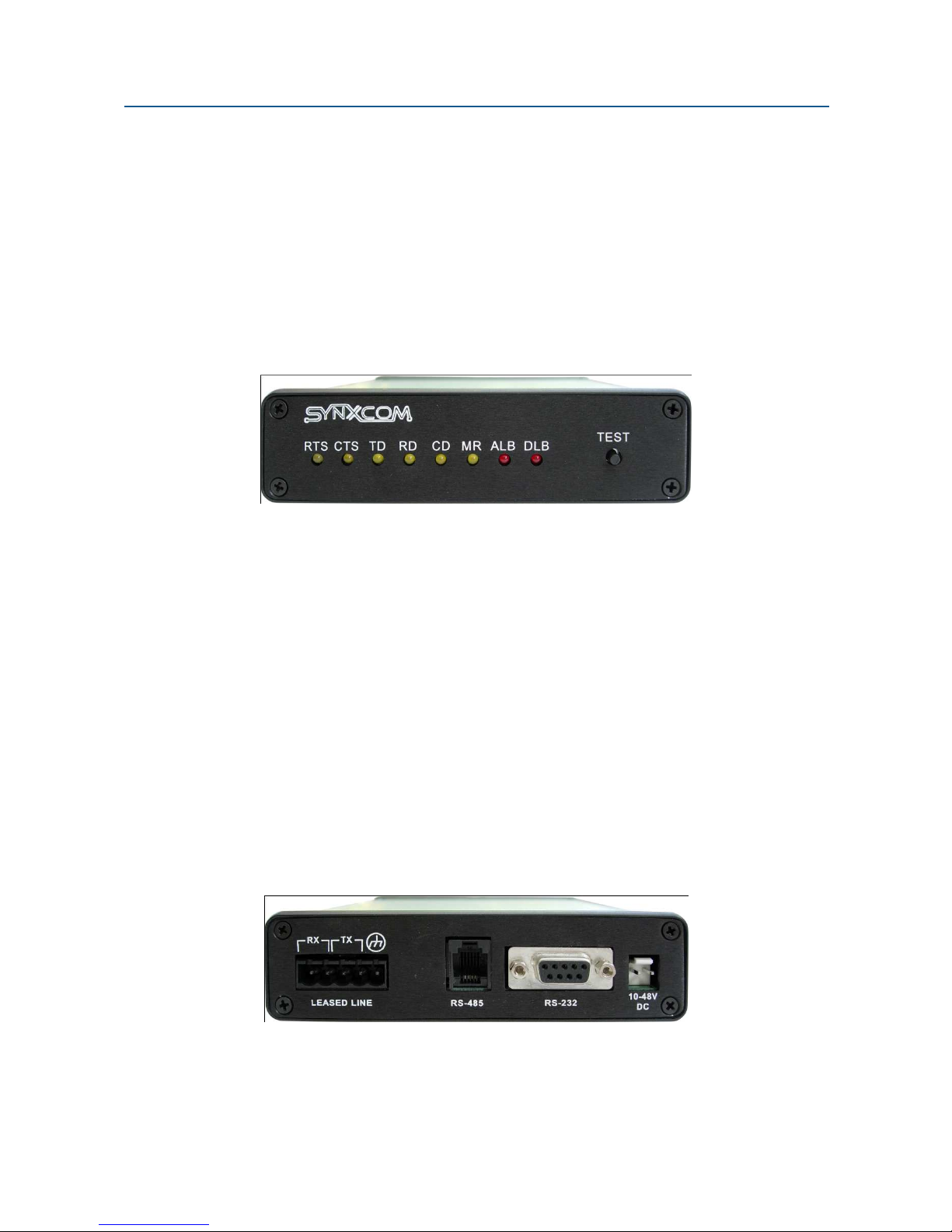
Figure 2-1 shows the front view of the SM19202FP stand-alone modem. Starting from the
left side, this view shows:
A set of eight LEDs for modem interface status (see Table 2-6 on page 26)
A loopback control push-button switch (see Loopback Control Switch on page 26)
Figure 2-1. Front View of the SM19202FP Modem
Back View
Figure 2-2 shows the back view of the SM19202FP stand-alone modem. Starting from the
left side, this view shows:
A 4-wire/2-wire configuration block labeled LEASED LINE
An RJ-11 modular jack labeled RS-485 for connecting the modem to an RS-485
RTU
A female, 9-pin RS-232 connector labeled RS-232 for connecting the modem to a
standard DTE (RTU)
A power connector labeled 10-48V DC
Figure 2-2. Back View of SM19202FP Modem
10 User’s Manual - SM19202 Fast Poll Modem
Page 11
Installation
Rack-Mount View
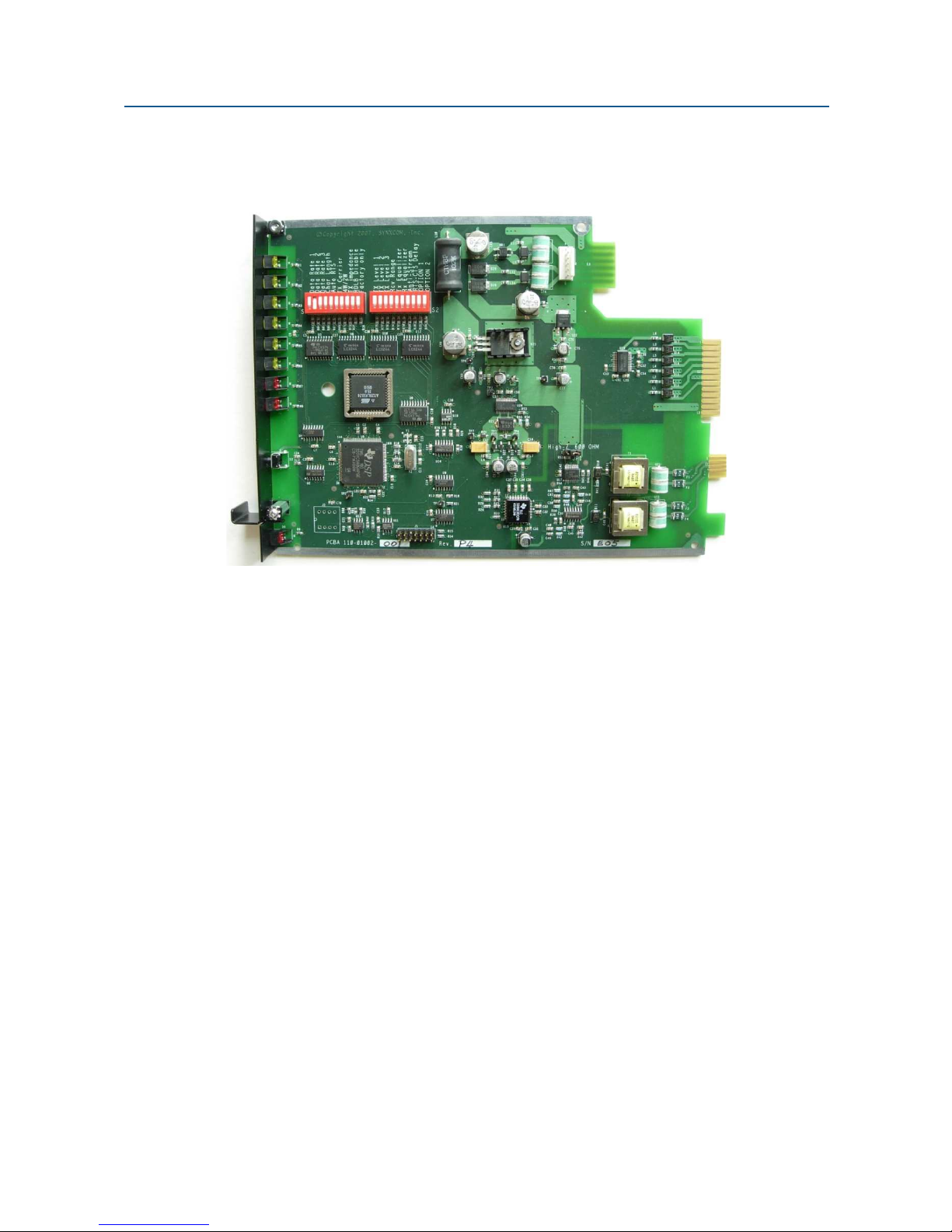
Figure 2-3 shows the rack-mount plug-in module.
Figure 2-3. Rack-Mount Module for the SM19202FP-RM Modem Board
Installation Summary
This section describes the steps for installing the modem.
NOTE:
1. Configure the modem using the DIP switches and jumpers. See pages 14 and 20.
2. Connect to a transmission line. See page 22.
3. Connect to a voltage source. See page 23.
4. Connect a DTE device. See page 24.
It is important to follow the steps below to configure the modem’s DIP
switches to match your DTE/RTU interface requirement and the transmission
line characteristics. If you are not certain about your system’s parameters or
the leased-line configuration, please contact your network administrator for
assistance.
11 User’s Manual - SM19202 Fast Poll Modem
Page 12

Installation
Configuring the Stand-alone Modem
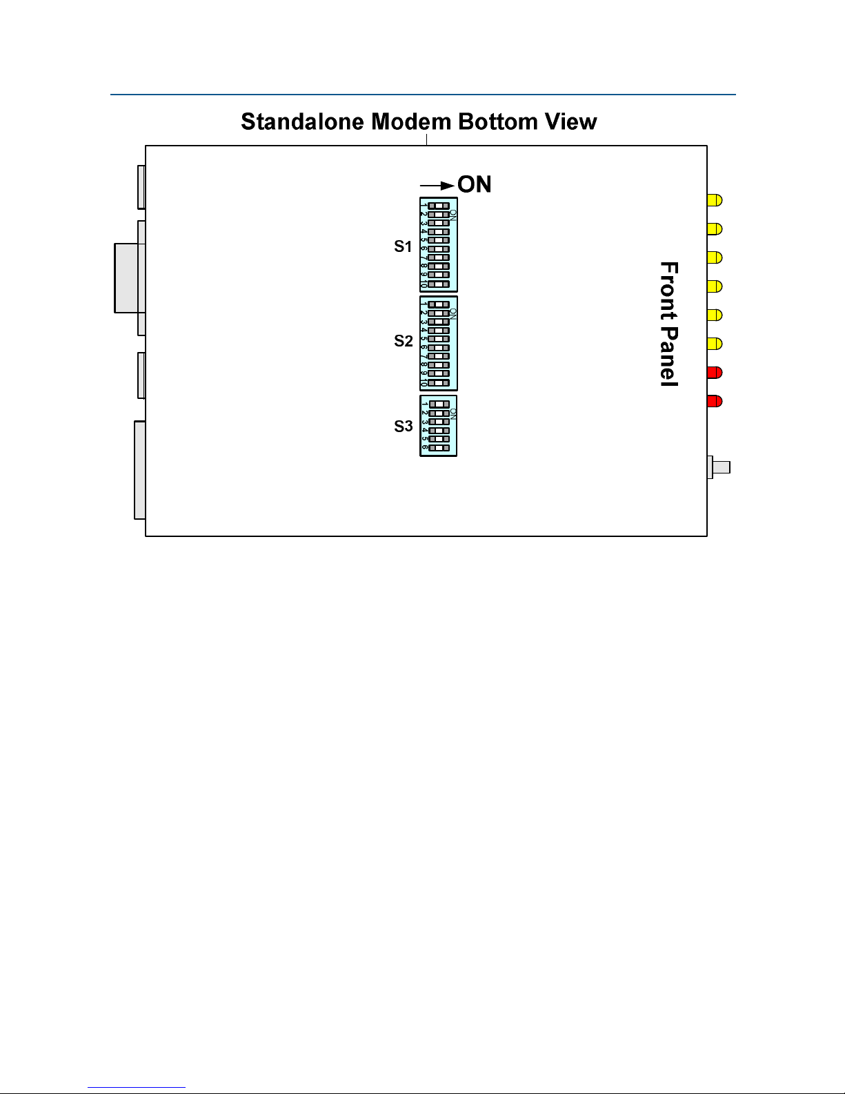
You configure the modem using the three sets of DIP switches located at the bottom of the
modem box S1 and S2, and S3.
Configuration DIP switches S1 and S2 for the stand-alone and rack-mount modems are
identical. Their descriptions in this user’s manual apply to both modem versions.
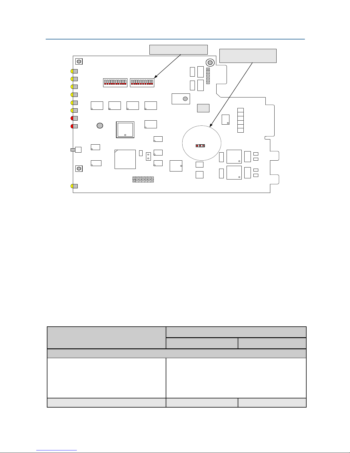
Configuration jumper JP1 for the rack-mount modem card is used to select receiver
termination impedance.
It is important to follow the steps described below, in the order shown, to ensure that you
configure your modem properly using the modem DIP switches:
1. Use DIP switch 1 (S1) to configure the modem for your host DTE interface and
network topology. Using S1, you select the modem’s operating speed to match
you host computer or RTU devices, and other DTE specific operating
parameters.
2. Use DIP switch 2 (S2) to select the modem’s transmitter output level and receiver
dynamic range specific leased line conditions. The S2 settings apply for both
high-speed fast-poll (QAM) and low-speed (FSK) modes.
3. After you change the DIP switch settings, recycle power to the modem to have
the settings take effect.
NOTE:
The DIP switch settings may not take effect until you recycle power to the
modem.
To access the configuration DIP switches on the stand-alone modem:
1. Ground yourself to discharge any ESD, which might cause damage to the
sensitive devices on the modem board.
2. Due to re-designing of the modem’s main assembly circuit board and the chassis,
you do not need to open the enclosure to get access to the DIP switches . Place
the modem on a flat surface with the bottom up. The locations of the DIP
switches for the stand-alone modem are shown in Figure 2-4 on the next page.
To set the configuration for the modem, use a sharp pin or small screw driver to
slide the switch lever to the ON or OFF positions as shown in Table 2-1.
For DIP switches and jumpers on the rack-mount plug-in module, see Figure 2-5.
***IMPORTANT***
Carefully check the DIP switches for the ON (close) or OFF (open) positions
according to your RTU interface specifications and to match the data rate and
other control inputs to the modem.
12 User’s Manual - SM19202 Fast Poll Modem
Page 13
Installation
Figure 2-4. SM19202 Fast-Poll Stand-alone Modem Switches
13 User’s Manual - SM19202 Fast Poll Modem
Page 14
Installation
Configuration DIP Switches
y
a
l
r
r
e
e
e
m
D
e
z
z
1
2
3
i
i
a
g
l
l
l
l
l
e
S
1
2
a
n
a
r
e
e
e
T
t
a
u
u
v
v
v
n
n
C
S
q
q
e
e
e
R
-
o
o
-
i
i
i
E
L
L
L
E
t
S
t
t
v
p
p
c
x
n
T
x
x
x
Data Rate 1
Data Rate 2
Data Rate 3
Char Length
Auto RTS
Tx Carrier
4W/2W
Tx Impedance
D2 D1D3D4D5D6D7D8D9
U3
S3
U4
U2
RDLB Disable
10
S1 S2
U8
U1
U5
x
Factory only
T
T
T
R
R
T
A
R
O
O
11
10
U21
U10
U12
U6
U14
Y1
Y2
U9
U7
U15
U15
2
1
J1
13 14
D27 D25
GT4 GT3
J2
U22
600 ohmHigh-Z
31
JP1
U17
U18
Configuration Jumper
for Receiver Termination
E3
U19
D11 D10
Figure 2-5. SM19202 Fast-Poll Rack-mount Modem Board
E2
T1
T2
F1
F2
F3
GT2 GT1
F4
E1
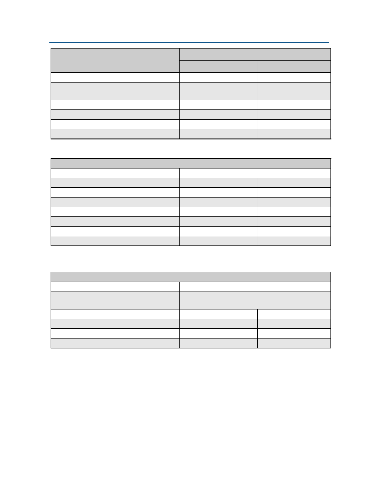
Setting the DIP Switches
S1, S2 and S3 are miniature switches used to configure all the options and features of the
modem. Table 2-1 shows the setting of the switches.
NOTE:
S1-1 to S1-3: Modem Data Rate
S1-4: DTE Async Character 11 bit 10 bit
Switches S1 to S3 are slide switches. To configure the switches, use a small
sharp pin or small screw driver to push the handle to turn ON or to turn OFF
each switch. Never leave any switch in half way ON or OFF. When the switch
is slide to the ON position, it is referring to as CLOSE condition. When the
switch is in the OFF position, it is in the OPEN state.
Table 2-1. Modem Switch Settings
Switch Settings
DIP Switches
ON OFF (Default)
DIP Switch S1
19200: SW1=OFF, SW2=OFF, SW3=OFF
9600: SW1=ON, SW2=OFF, SW3=OFF
4800: SW1=ON, SW2= ON, SW3=OFF
2400: SW1=OFF, SW2=ON, SW3=OFF
Bell 202T: SW1=OFF, SW2= OFF, SW3=ON
V.23: SW1=ON, SW2=ON, SW3=ON
14 User’s Manual - SM19202 Fast Poll Modem
Page 15
Installation
DIP Switches
Switch Settings
ON OFF (Default)
S1-5: Auto RTS Enabled Disabled
S1-6: Transmit Carrier Control
(SM19202FP-K only)
S1-7: 2- or 4-wire leased line 2-wire half duplex 4-wire full duplex
S1-8: Transmitter Impedance Controlled by RTS 600 ohms
S1-9: Remote Digital Loopback Enabled Disabled
S1-10: Test Only (Reserved) Factory Test only Normal Operation
S2-1 to S2-3: Transmit Output Level From -14 to 0 dBm (see Table 2-5)
S2-4: Modem Receive Dynamic Range -10 to -43dBm 0 to -30dBm
S2-5: TX Cable Equalizer Enabled Disabled
S2-6: RX Cable Equalizer Enabled Disabled
S2-7: Anti-streaming Active Inactive
S2-8: RTS-CTS Delay (Bell 202T only) 33 msec 8 msec
S2-9: Forced RTS ON Force RTS & Carrier to ON Controlled by RTS signal
S2-10: Re-Train Enabled (19200 bps only) Enabled Disabled
S3-1: RS-232 Interface operation Both S3-1 and S3-2 are set to OFF
S3-2: RS-485, 4-wire interface
2-wire interface
S3-3: RS-485, Receiver Termination High Impedance 120 Ohms
S3-4: Not Used
S3-5: Receiver Termination 600 Ohms (Default) High Impedance
S3-6: Signal Ground and Chassis Ground Connected Together Open
Radio Push-to-Talk option Normal Leased Line
DIP Switch S2
DIP Switch S3
S3-1 = ON, S3-2 = OFF
S3-1 = OFF, S3-2 = ON
S1-1, S1-2, S1-3 −−−− Modem Data Rate
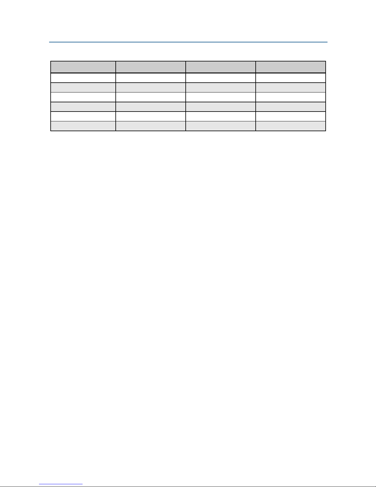
S1-1, S1-2, S1-3: Select the modem speed per Table 2-2
15 User’s Manual - SM19202 Fast Poll Modem
Page 16
Installation
Table 2-2. Modem Operating Speed
To Select… Set Switch S1-1 to… Set Switch S1-2 to… Set Switch S1-3 to…
19,200 bps (Note) OFF OFF OFF
9600 bps ON OFF OFF
4800 bps ON ON OFF
2400 bps OFF ON OFF
Bell 202T OFF OFF ON
V.23/1200 ON ON ON
For modem speeds of 2400 bps or higher, the modem uses QAM modulation automatically.
When the modem is operating at 1200 bps either in Bell202T or ITU-V.23 mode, the modem
uses FSK modulation.
Note: Leased lines with a relatively flat 300-3400Hz bandwidth is required to support
19,200 bps operation.
S1-4 −−−− Async Character (Fast-Poll Mode Only)
S1-4 ON = 11 bits
S1-4 OFF = 10 bits (default)
Switch S1-4 selects whether the async character is 10 or 11 bits long.
10 bits character: 1 start, 1 stop bit, 7 data + 1 parity(&-E-1), or 8 data with no parity(8-N-1).
11 bits character: 1 start, 1 stop bit, 8 data + 1 parity (8-E-1)
This switch setting is ignored when the modem set at 1200 bps or less (FSK modulation).
S1-5 −−−− Auto RTS
S1-5 ON = Enable Auto RTS
S1-5 OFF = Disable Auto RTS (default)
For data terminals that do not provide hardware Request To Send (RTS), i.e. only provide
TXD, RXD, SG connections, set the modem’s switch S1-5 to ON to enable auto RTS mode.
In this mode, the modem does not require RTS input from the DTE or RTU. If TXD is
detected at the modem, the modem turns on its internal RTS and carrier signals at the
transmitter. After training completes, the TXD is transmitted to the remote modem. The
transmitter turns itself off if no TXD is detected after some length of idle time (approx 2
characters).
S1-6 −−−− Transmit Carrier Control (For SM19202FP-K only)
S1-6 ON = Enable transmit carrier control for radio push-to-talk
16 User’s Manual - SM19202 Fast Poll Modem
Page 17

Installation
S1-6 OFF = Normal Leased Line operation (default)
When DIP switch SW1-6 is ON, the modem will activate its Push-To-Talk feature. The
main theory of operation of this feature is for the modem to turn on the radio as soon as
RTS is asserted by the RTU to the SM19202FP-K modem. The modem will use the
delayed Clear-To-Send (CTS) as the indicator to the RTU to signal the start of sending data
to the host end. When the modem turns on the radio by way of a TTL logic low signal (Keyon), the modem will wait for 30 msec before start sending any analog signal to the radio
and the master modem end. This timing is critical and is required by the radio and the
modem to ensure the training pattern of the modem is fully transmitted without distortion.
For RTUs that only provide the 3-wire RS-232 interface, or using the RS-485 interface, the
modem will not receive the RTS signal for the key-on function. As such, the modem must
be configured to enable the “Auto-RTS” option (SW1-5 to ON). With this option, the
modem will generate its internal RTS when data is detected from the RTU and turn on the
“Push-To-Talk” signal to the radio.
Note: Please refer to switch setting S2-9; forced RTS ON for other applications.
S1-7 −−−− 2-/4-Wire Leased Line Operation
S1-7 ON = 2-Wire, Half-Duplex Mode
S1-7 OFF = 4-Wire, Full-Duplex Mode (default)
Switch S1-7 configures the modem for either 4-wire full-duplex or 2-wire half-duplex leased
line operation.
S1-8 −−−− Transmitter Impedance
S1-8 ON = Transmitter termination is controlled by RTS
S1-8 OFF = Transmitter always terminated with 600 Ω (default)
Switch S1-8 is used for multi-point configuration networks. When multiple modems are
connected on the same metallic circuit:
The transmitter termination should be of high impedance if the modem is not
transmitting in order not to put a load on the transmission line.
The transmitter is only terminated with 600 ohms when RTS is asserted.
This configuration should be used for all slave modems to prevent the transmitting modem
from being unnecessarily burdened. To select this configuration, set switch S1-8 ON for the
slave modems such that the slave modem is in high impedance when not transmitting.
17 User’s Manual - SM19202 Fast Poll Modem
Page 18
Installation
If you use the modem with transmission lines that are transformer-coupled or with an
impedance-isolated network (such as a transformer bridge), set switch S1-8 OFF for proper
operation.
S1-9 −−−− Remote Loopback Enable
S1-9 ON = Loopback enabled
S1-9 OFF = Loopback disabled (default)
During instances of channel noise, the modem may mistake a received preamble as a
request to go into remote digital loopback. Setting switch S1-9 to OFF prevents the modem
from participating in a remote digital loopback with another modem. Switch S1-9 does not
prevent the modem from sending a remote digital loopback request to a remote modem.
S1-10 −−−− Reserved (Test Only)
S1-10 = must be OFF for normal modem opertation
Switch S1-10 must be in the OFF position for normal operation. It is reserved for factory
testing only.
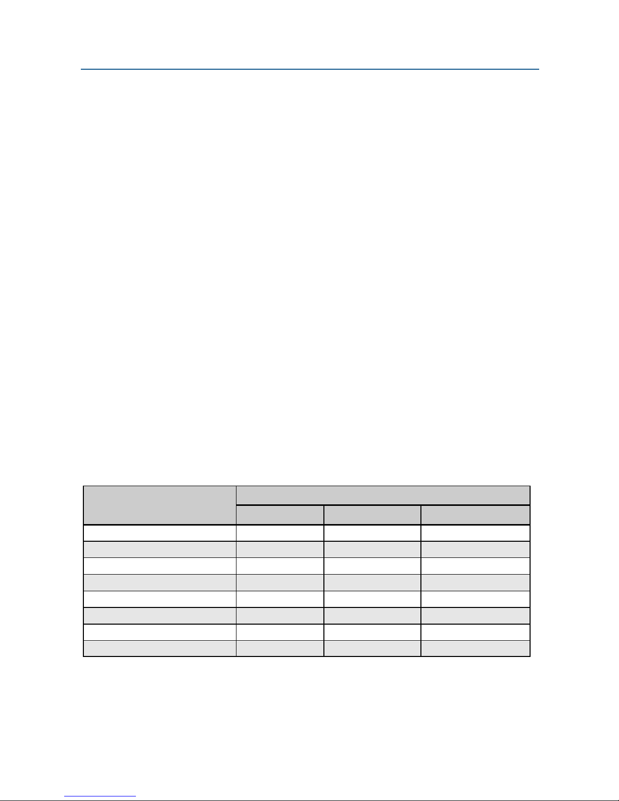
S2-1 through S2-3 −−−− Transmit Level
Switches S2-1 through S2-3 are used to adjust the modem’s transmit level. Table 2-5 shows
the transmit levels you can select using these switches.
Table 2-3. Transmit Levels
Transmit Level
0 dBm OFF OFF OFF
−2 dBm
−4 dBm
−6 dBm
−8 dBm
−10 dBm
−12 dBm
-14 dBm ON ON ON
S2-1 S2-2 S2-3
OFF OFF ON
OFF ON OFF
OFF ON ON
S2-1 through S2-3 Switch Settings
ON OFF OFF
ON OFF ON
ON ON OFF
18 User’s Manual - SM19202 Fast Poll Modem
Page 19

Installation
S2-4 −−−− Receiver Dynamic Range
S2-4 ON = −10 to −43 dBm
S2-4 OFF = 0 to −30 dBm (default)
For short distances or to select a strong receive signal, set S2-4 to OFF. For a long-distance
cable or low receive signal level, set S2-4 to ON (−43 dBm).
S2-5 and S2-6 −−−− Cable Equalizer (Fast-Poll Mode Only)
S2-5 ON = Enable TX Cable Equalizer
S2-5 OFF = Disable TX Cable Equalizer (default)
S2-6 ON = Enable RX Cable Equalizer
S2-6 OFF = Disable RX Cable Equalizer (default)
If you use the SM19202FP as a limited-distance modem over pilot wire or unloaded cables,
you may need to improve or extend the modem’s polling performance on long transmission
lines by using the modem’s internal fixed Compromise Cable Equalizer when polling on long
metallic circuits when the cable exceeds 4 to 5 miles long. The cable equalizer is active only
when the modem is in QAM fast-poll mode (2400 bps or higher).
S2-7 −−−− Anti-streaming
S2-7 ON = Anti-streaming is active
S2-7 OFF = Anti-stream is inactive (default)
Typically, anti-streaming is used in multi-point applications to prevent a malfunctioning slave
data terminal or RTU from occupying the line indefinitely. When anti-streaming is active, the
modem can transmit data for a maximum of 27 seconds before the transmitter turns off
automatically. The modem then looks for an ON-to-OFF RTS transition before proceeding
with normal operation. Anti-streaming can be selected in either high-speed or low-speed
mode.
S2-8 −−−− RTS-CTS Delay (Bell 202 Mode Only)
S2-8 ON = 33.0 ms delay
S2-8 OFF = 8.0 ms delay (default)
Switches S2-8 determines the duration of the RTS-CTS delay in Bell 202 mode.
For V.23 mode, the RTS-CTS delay is fixed at 33 ms.
19 User’s Manual - SM19202 Fast Poll Modem
Page 20

Installation
S2- 9−−−− Forced RTS ON (Constant RTS)
S2-9 ON = Force the modem’s internal RTS to on. It also force the modem to turn
on CTS and the transmit carrier.
S2-9 OFF = Internal RTS is controlled by the RTU (default)
Switch 2-9 will force the modem to turn on its internal RTS, CTS and transmit carrier
continuously, allowing the RTU and DTE to operate with the modem without supplying RTS
signal. This is primary used by DTE’s or RTU’s that support only TD, RD and SG signals.
Forced RTS on option is typically used for point-to-point connections between two RTUs or
modems. For multi-point applications, the salve modems should not use this option.
S2- 10−
− Re-Train Request Enabled
−−
When the SM19202FP modems are operating in high-speed polling modes, the modem’s
receivers require a special training pattern from the remote transmit modem to synchronize
the receive timing before data can be received. The SM19202FP will only send out a training
pattern when the transmit modem’s RTS is raised from the OFF to ON state (i.e. Switched
Carrier mode). However, if the modems are configured in Constant Carrier mode, or the
RTS is ON continuously by the DIP switches, no training pattern will be sent from the
transmit modems. When in configurations where constant carrier is received at the
modem’s receiver, there is a possibility that the modem might lose synchronization due to
transmission line interferences such as line hits, line drop-outs, or power outage conditions.
In order to regain synchronization at the receiver, the SM19202FP modem implements a retrain algorithm which allows the receiving modem to send out a re-train request to the
remote modem for re-train and re-gain synchronization. This option is most useful for the
modem to operate at 19200 bps and constant carrier or constant RTS modes.
S2-10 ON = Re-Train Request is Enabled (for 19,200 bps only)
S2-10 OFF = Re-Train Request is Disabled (default)
S3- 1 and S3-2−−−− RS-232 or RS-485 Interface Select
The SM19202FP standalone modem support either RS-232/V24 or RS-485 4-wire or RS485 2-wire operation. To select the interface standards to match you RTU, configure S3-1
and S3-2 as following:
• RS-232/V.24: S3-1 = OFF, S3-2 = OFF
• RS-485, 4-wire: S3-1 = ON, S3-2 = OFF
• RS-485, 2-wire: S3-1 = OFF, S3-2 = ON
20 User’s Manual - SM19202 Fast Poll Modem
Page 21

Installation
S3-3 RS-485 Receiver Termination
When RS-485 is used, a 120 ohm receiver termination may be used to terminate the
receiver.
• S3-3 ON, a 120 ohms load is placed across the RX+ and RX- signal
• S3-3: OFF, no termination is connected to the receiver
S3-4- Not Used
S-3-5 Leased Line Receiver Termination
S3-5 ON: The modem leased line receiver is terminated with 600 ohms (default)
S3-5 OFF: The modem’s line receiver is set high input impedance (multi-point)
S3-6- Common Signal Ground and Chassis Ground
S3-6 ON: The modem chassis ground and signal ground are connected
S3-6 OFF: The modem chassis ground and signal ground are not connected.
Configuring the Jumper Blocks
For Stand-alone Units
No internal jumper block is required.
For Rack-Mount Plug-in Modules
Jumper block JP1 is used to set the modem’s receiver termination impedance
• 600 ohms: A shorting jumper is placed over pin 2 & 3 (default)
• High impedance: A shorting jumper is placed over pin 1 & 2
Select high receiver impedance (Hi-Z) if multiple modems are connected in a multipoint configuration but without an impedance matching bridged such as private
metallic circuit environment. In this configuration, only one receiver should be
configured for 600 ohms.
21 User’s Manual - SM19202 Fast Poll Modem
Page 22
Installation
Connecting to a Transmission Line
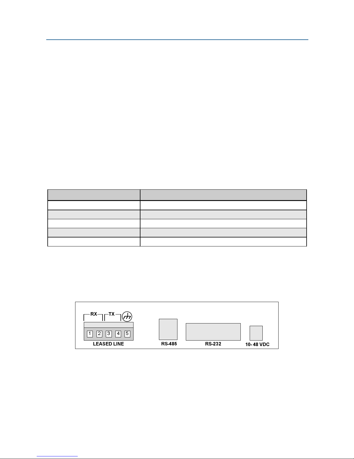
The modem has a transmission line interface that can be configured for 2- or 4-wire analog
connection, where one pair (Tx-A and Tx-B) is used to transmit data and the other pair (Rx-A
and Rx-B) is used to receive data. The transmit pair and receive pair are non-polarized.
Table 2-4 shows the pin numbers and corresponding signals for the modem. Figure 2-6
shows the transmission line interface.
NOTE:
For communication to occur, the Rx line of one modem must connect to the Tx
line of the other modem. The modem’s Tx/Rx pair are non-polarized.
NOTE:
The modem does not support leased-line operation with DC shielding current.
Leased-line connector pin assignments for the rack-mount module can be
found in the documentation for your Motorola/UDS RM16M.
Table 2-4. Transmission Line Connector Pin Assignments
This Pin Number… Corresponds to This Signal…
1 Rx (4-wire only)
2 Rx (4-wire only)
3 Tx (Tx/Rx-2-wire)
4 Tx (Tx/Rx-4-wire)
5 Earth Ground (optional)
NOTE:
When 2-wire half duplex is used, the TX pair must be used for both transmit
and receive.
Figure 2-6. SM19202FP Modem Transmission Line Interface
22 User’s Manual - SM19202 Fast Poll Modem
Page 23

Installation
Connecting to a Voltage Source
The back panel of the modem provides a 2-position screw terminal power interface
connector. For your convenience, the DC voltage of the input power is non-polarized. To
meet your specific application, the modems can be powered from the following power
sources:
Model SM19202FP (with AC-DC power converter): 90 to 265 Volts AC, 50 to 60
Hz, single phase or 100 to 400 VDC. The output of the converter is a 12 VDC
source that will power the modem.
Model SM19202FP-DC (DC version): 10 to 60 Volts DC. The model SM19202FP-
DC comes with a power cord for making this connection.
Figure 2-2 on page 10 shows the connection to the Model SM1920FP’s power interface
shows the connection to the Model SM19202FP-DC’s power interface.
WARNING:
Before you connect a voltage source, observe the following power supply
voltage guidelines. Otherwise, you will void your warranty if the wrong voltage
is applied.
Be sure the voltage source is within the permitted ranges shown
above. Otherwise, your modem and any attached devices may be
damaged.
Customer-supplied cables must be suitable for the site
environmental conditions.
Screw terminals on the power interface accept 24 to 16 AWG.
However, surge protection is effective only if there is a solidly
earthed ground connection greater than 18 AWG.
Be sure the power source is not controlled by a wall switch, which
can be inadvertently turned off, shutting off power to the modem.
23 User’s Manual - SM19202 Fast Poll Modem
Page 24
Installation
Connecting to an RS-232 Device
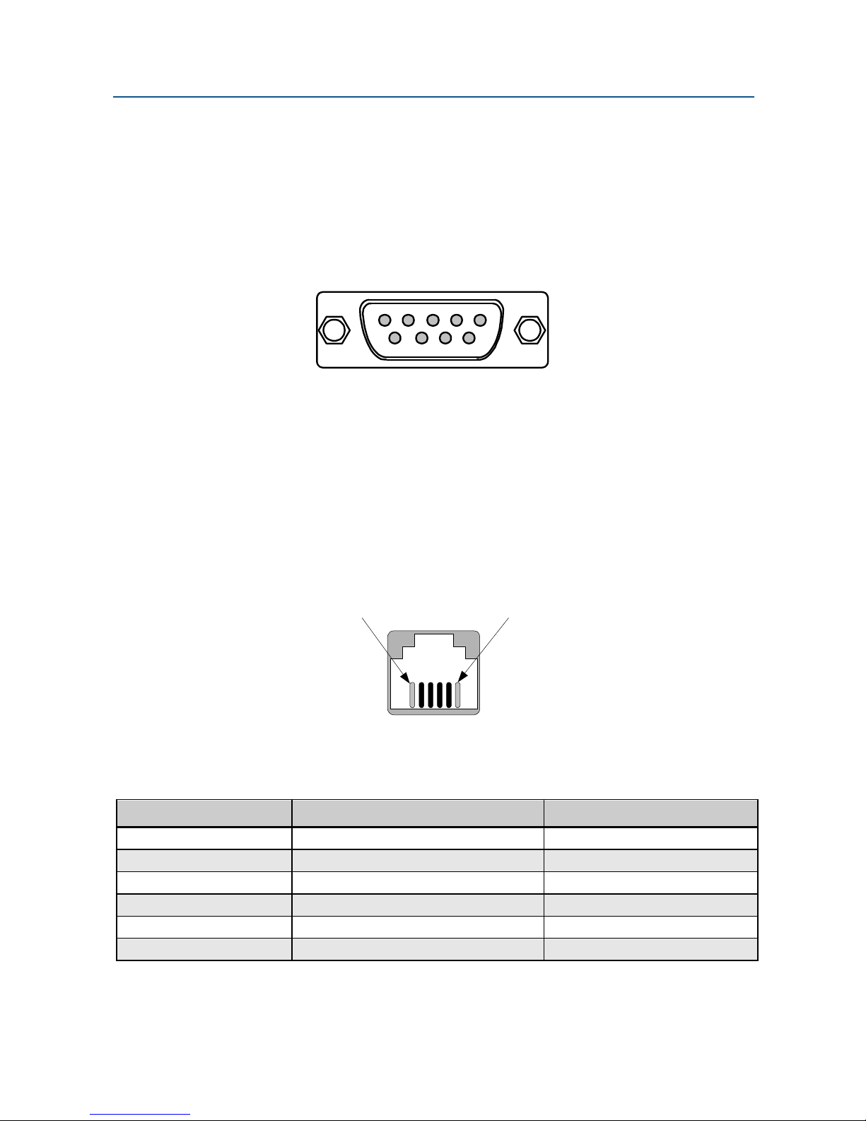
The modem back panel provides a female, 9-pin RS-232 connector that accepts an attached
RS-232 device (see Figure 2-2 on page 10). This connector accepts a standard connection
to a DTE (RTU) that conforms to the pin assignments shown under Table B-2 “RS-232
(DTE) Interface” in Appendix B.
3
45
12
6789
Connecting to an RS-485 Device
The modem rear panel provide an RJ-11C module jack connector for a 4-pin RS-485 or RS422 interface in the event that your DTE or RTU does not support the RS-232 interface (see
Figure 2-2 on page 10 and Figure 2-7). The RS-485 interface supports 4-wire full duplex or
2-wire half duplex.
The pin assignments for the RS-485 interface are listed in Table 2-5.
Pin #6 Pin #1
Figure 2-7. Pin Locations on the Modem’s RJ-11C Jack
Table 2-5. RJ-11C Modular Jack Pin Assignments
RJ-11 Pin Number… Corresponds to Signal Name Modem Input or Output
1 Not Used NA
2 RxD+ Output
3 RxD- Output
4 TxD+ Input
5 TxD- Input
6 Not Used NA
24 User’s Manual - SM19202 Fast Poll Modem
Page 25
Installation
Modem
RJ-11C
Modem
RJ-11C
DTE / RTU
RxD+
2
RxD-
3
TxD+
4
TxD-
5
4 wire RS-485 Connection
DTE / RTU
RxD+ / TxD+
2
RxD- / TxD-
3
4
Not Used
5
2 wire RS-485 Connection
25 User’s Manual - SM19202 Fast Poll Modem
Page 26
Installation
LEDs
The front panel of the modem provides the LEDs shown in Table 2-5.
Table 2-6. Modem LEDs
LED Color Description
RTS Yellow Request To Send
CTS Yellow Clear To Send
TD Yellow Transmit Data
RD Yellow Receive Data
CD Yellow Carrier Detect
MR Yellow Modem Ready
ALB Red* Analog Loopback
DLB Red* Digital Loopback
* When the modem is in remote loopback, both the ALB and DLB LEDs go ON.
Loopback Control Switch
The front panel of the modem has a push button for initiating the following loopback
diagnostic tests:
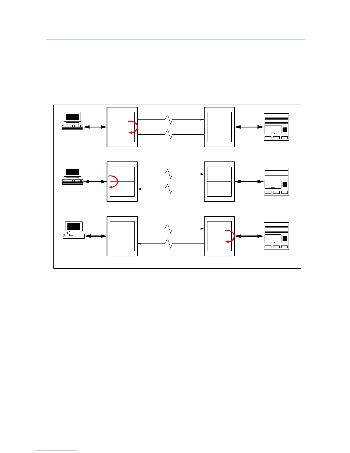
Local analog loopback started by pressing the button one time. The ALB LED
should be ON. When a DTE is connected to the RS-232 port of the modem, the
transmit data is loop back to the DTE as receive data. This test will verify the
modem transmitter, receiver, and its RS-232 interface along with the connecting
cable.
Local digital loopback started by pressing the button two times. The DLB LED
should be ON. When a DTE is connected to the RS-232 port of the modem, the
transmit data is loop back to the DTE as receive data. This test will verify the
modem’s RS-232 interface along with the cable attached.
Remote digital loopback set the local modem’s RTS signal to low. Press the
local modem’s diagnostics test button three times. Both the ALB and DLB LEDs
should be ON. Then raise the local modem’s RTS signal to start the test. The ALB
and DLB LEDs of the remote modem should go ON when the modem is
responded to remote digital loopback. This test will verify both modems’
transmitters, receivers, and the leased line
26 User’s Manual - SM19202 Fast Poll Modem
Page 27
Installation
NOTE:
Be sure switch S1-9 is set to the ON position to enable the remote modem to
respond to remote digital loopback requests. This test is only available in fast-
poll mode at 2400 bps or higher.
Figure 2-8 shows these three loopback diagnostics.
Transmitter
HOST
HOST
Receiver
Local (Host) Analog Loop Back
Transmitter
Receiver
Local (Host) Digital Loop Back
Leased Line
Leased Line
Receiver
Transmitter
RTU
Receiver
Transmitter
RTU
HOST
Transmitter
Leased Line
Receiver Transmitter
Remote (RTU) Digital Loop Back
Receiver
RTU
Figure 2-8. Loopback Diagnostic Modes
27 User’s Manual - SM19202 Fast Poll Modem
Page 28
Appendix A
Troubleshoot
In the event you encounter a problem using your Synxcom modem, refer to the
troubleshooting information in this appendix.
ing
IMPORTANT:
If you encounter a problem with your modem, be sure the switches on the
modem are set to the appropriate positions (see Table 2-1 on page 14). If
a switch is halfway between an on and off setting, the modem will not
operate properly.
Problem Solving
Table A-1 offers troubleshooting solutions for modem problems.
Table A-1 Problem Solving
If… Perform These Procedures…
No LEDs are ON at the front
panel
Modem does not respond to the
attached DTE and the all LEDs
are off.
Modem does not receive data,
and the DCD and RxD LEDs are
off.
The RTS, CTS, and TxD LEDs
do not blink.
Check the power supply source. Be sure the input power to the
modem’s power connector is between 10 to 60VDC .
The MR LED should be on if the modem is powered up properly and
when it is not in any loopback test mode.
Check the connecting RS-232 or RS-485 cable between the DTE and
the modem. The MR/DSR LED (Modem Ready/Data Set Ready) on
the front panel should be ON when the modem is idle.
Check the DIP switches of both modems to make sure that the same
data rate and operating parameters are identical on both modems.
The receive line pair may be disconnected from the modem. Make
sure the transmission line connection to the modem is accurate and
secure.
The receive signal level may be below the CD threshold. Set switch
S1-5 ON to see whether configuring the modem for a −43 dBm
threshold resolves the problem.
If this problem remains unresolved, perform a local ALB loopback
test to determine if the modem’s receiver is functioning correctly.
The attached terminal or DTE may not be sending data to the
modem. Verify that data is being transmitted. If data is being
transmitted, make sure the RS-232 cable is sound and securely
connected to the modem and terminal or DTE.
28 User’s Manual - SM19202 Fast Poll Modem
Page 29

Appendix B
Specification
General Specifications
Data rate: 19200, 9600, 4800, 2400, 0-1800 (Bell 202T), or 0-1200 bps (V.23)
asynchronous
s
Modem Training Time:
(RTS-CTS Delay)
Data format: 8 or 9 data bits with 1 or more stop bits, or 7 data bit with parity bit
DTE interface: EIA RS-232/V.24, or RS-485 (2-wire HD or 4-wire FD) compatible
Line conditions: TELCO voice band 4- or 2-wire leased line, conditioned or unconditioned
Operating modes: 2-wire half-duplex or 4-wire full-duplex over leased or private line
Modulation: QAM High-speed fast poll mode
Equalizer Automatic, adaptive
Receiver dynamic range: 0 to –30 dBm or –10 to –43 dBm
Operating temperature:
17.4 ms. (fast poll at 19200 bps)
23 ms. (fast poll at 2400/4800/9600 bps )
8 or 33 ms (Bell 202T)
33 ms (V.23)
Private metallic circuits up to 9.5 miles at 9600 bps (24 AWG) without cable
equalizer. Up to 15.0 miles (24 AWG) with TX and RX cable equalizer. Up
to 25 miles for FSK modes.
FSK, Bell 202T or V.23 compatible
• Mark = 1200 Hz (1300 Hz, V.23)
• Space = 2200 Hz (2100 Hz, V.23)
• Soft Carrier = 900 Hz (Bell 202T only)
-40°C to +85°C
Power supply: Wide range switching power supply:
Surge protection: Leased line, up to 15KV
Carrier control: Constant or switched, DIP switch selectable
Carrier loss recovery: Train on data automatically
Throughput delay: Less than 10 milliseconds for fast polling
Auto RTS: Support DTE without hardware RTS
29 User’s Manual - SM19202 Fast Poll Modem
• SM19202FP (AC version): 90 to 265 Volts AC, 50/60 Hz, single
phase or 90 to 400 VDC
• SM19202FP-DC (DC version):10 to 60 Volts DC
Page 30
Specifications
Anti-streaming: 27-second timer to prevent transmitter lock-up network
Mechanical Specifications
Enclosure: Aluminum with removable front and rear panels
Dimensions: 5.0” wide x 6.5” long x 1.30” high
Weight: 1.0 lbs without AC to DC power converter module
Interface connectors
Leased Line: 5-position screw terminal (includes earth ground)
Data Terminal Equipment: DB-9 female connector (for RS-232)
RJ-11C modular jack (for RS-485)
Interface Connector Pin Assignments
Table B-1. Leased Line Terminal Block Pin Assignments
This Pin Number… Corresponds to This Signal…
1 Rx
2 Rx
3 Tx
4 Tx
5 Earth Ground (optional)
NOTE:
When 2-wire half-duplex is used, the TX pair must be used for both transmit
and receive.
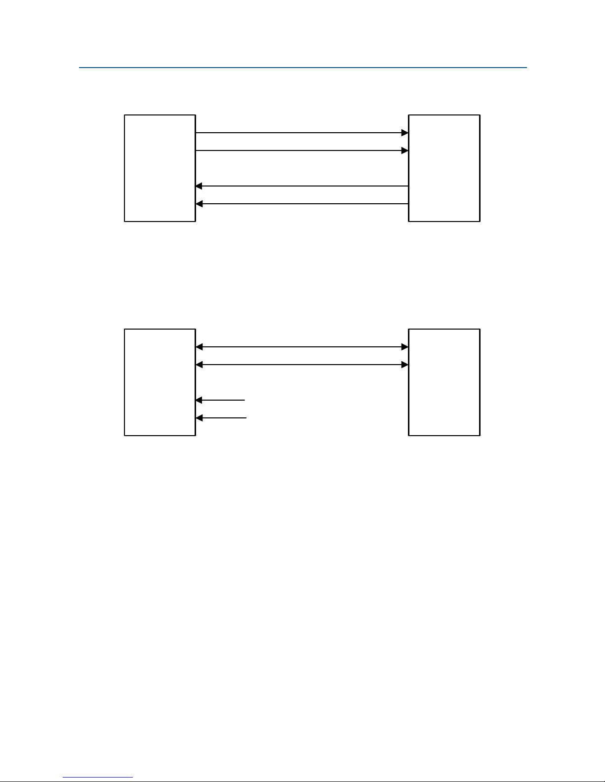
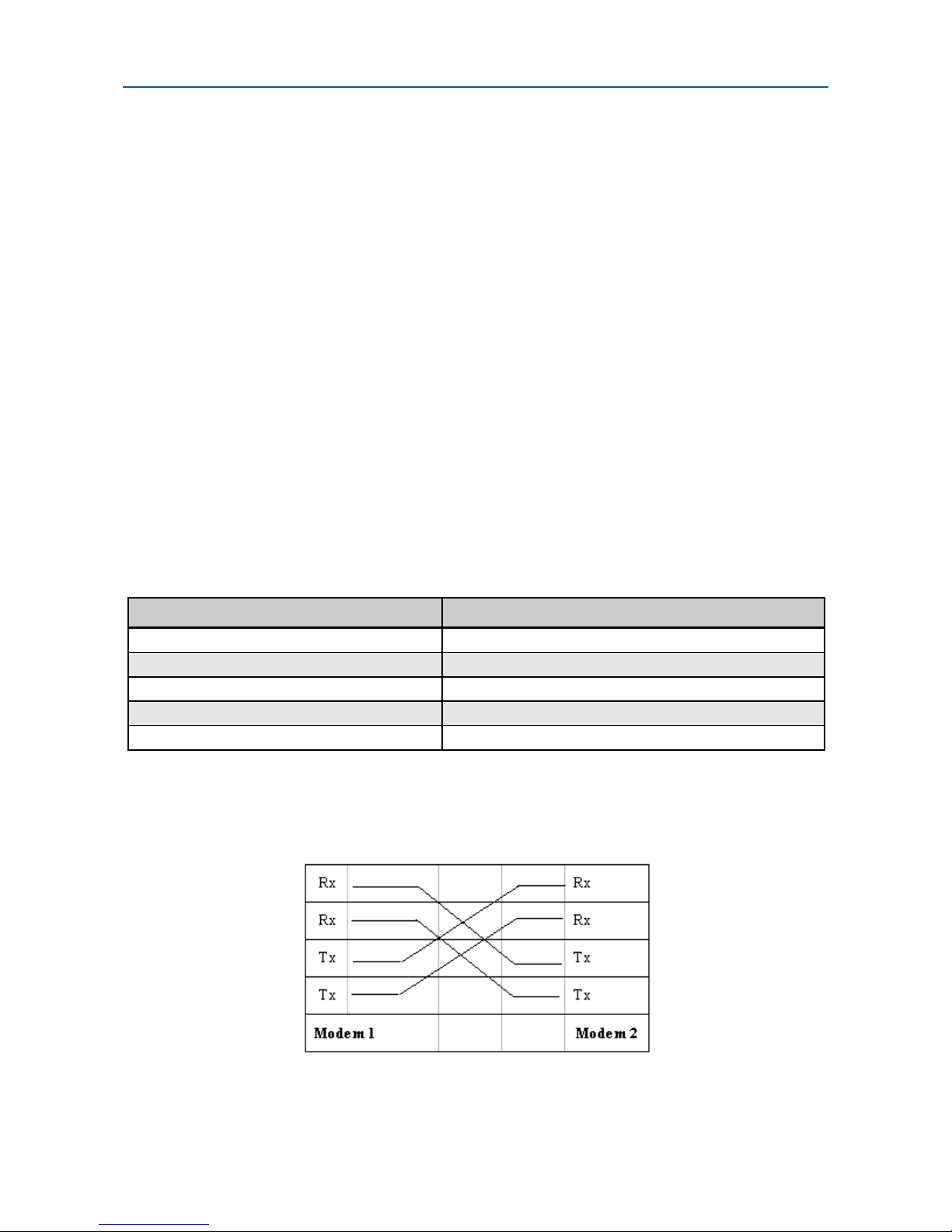
Figure 2-9. Back-to-Back Connection to a Second Modem
30 User’s Manual - SM19202 Fast Poll Modem
Page 31
Specifications
RS-232 (DTE) Interface
Table B-2. RS-232 (DTE) Interface
Signal Name Modem Input/Output DB-9 Pin Description
DCD Output 1 Data Carrier Detected
RXD Output 2 Receive Data
TXD Input 3 Transmit Data
SG
DSR Output 6
RTS Input 7 Request To Send
CTS Output 8 Clear To Send
5 Signal Ground
Data Set Ready
(Modem Ready)
RS-485 (DTE) Interface
Table B-3. RS-485 (DTE) Interface
RJ-11 Pin Number… Corresponds to Signal Name Modem Input or Output
1 Not Used NA
2 RxD+ Output
3 RxD- Output
4 TxD+ Input
5 TxD- Input
6 Not Used NA
Environmental Specifications
Operating temperature: -40 to + 85o C
Storage temperature: -40 to +125o C
Operating humidity: 5 to 95 %, non-condensing
Line isolation: 3750 V RMS
Surge protection: Leased line up to 15K VA
31 User’s Manual - SM19202 Fast Poll Modem
Page 32

Appendix C
Limited
Product
Warranty
Synxcom warrants that the Product sold will be free from defects in material and
workmanship and perform to Synxcom' applicable published specifications for a period of 24
months from the date of delivery to Customer. The liability of Synxcom hereunder shall be
limited to replacing or repairing, at its option, any defective Products that are returned F.O.B.
to Synxcom's Irvine, California facility (or, at Synxcom's option, refunding the purchase price
of such products). In no case are Products to be returned without first obtaining permission
and a customer return order number from Synxcom. In no event shall Synxcom be liable for
any consequential or incidental damages.
Products that have been subject to abuse, misuse, accident, alteration, neglect,
unauthorized repair or installation are not covered by the warranty. Synxcom shall make the
final determination as to the existence and cause of any alleged defect. No liability is
assumed for expendable items such as lamps and fuses. No warranty is made with respect
to custom products or Products produced to Customer's specifications except as specifically
stated in writing by Synxcom in the agreement for such custom products.
Warranty is voided if the serial number label on the printed
circuit assembly of returned modems is removed, defaced,
or destroyed. This label contains the serial number that
will provide proof of the date of manufacturing.
This warranty is the only warranty made by Synxcom with respect to the goods delivered
hereunder, and may be modified or amended only by a written instrument signed by a duly
authorized officer or Synxcom and accepted by Customer.
This warranty and limitation extends to customer and to users of the product and is in lieu of
all warranties with respect to the product whether express, implied, or statutory, including
without limitation the implied warranties of merchantability and fitness for a particular
purpose.
32 User’s Manual - SM19202 Fast Poll Modem
Page 33

Appendix D
RMA
Procedure
Before returning any Synxcom product, an RMA number must be obtained. Before asking for an
RMA number, ascertain that the product was purchased from Synxcom. If you bought the
product from a Distributor or Systems Integrator, the product should be returned to that vendor.
The most convenient method to obtain an RMA number for a product purchased from Synxcom
is to fill out and submit the RMA form on-line, or send an email to [email protected].
Information required must include:
Company name
Address (including any Mail Stop or specific delivery information)
Name, contact information, and e-mail address for the technical contact(s) at your company
If the above information is on your letterhead, that format is acceptable.
For each item you wish to return, please include:
The product model number (usually found on the serial number tag)
The serial number for each item you wish to return
A description of the problem you are encountering
The cause of the problem (if known)
A product support specialist may call to verify that the product is properly installed or may ask
you to perform tests to insure that the product has actually failed. After reviewing the problem,
Synxcom will assign an RMA number and you will be notified by email or FAX.
The product must be properly packed and returned to:
Synxcom Inc.
10 Lee
Irvine, CA 92620
Attn: Technical Support
The RMA number must be legibly displayed on the shipping carton. No RMAs will be
issued without a product review. Synxcom will not be responsible for any product
returned without an RMA number.
If you believe the product may be out of warranty, include a method of payment for repairs (either
a Purchase Order number or credit card number), card holder name, date of expiration on the
RMA request. Repairs currently require 5 working days and are returned UPS second day air.
Contact us by e-mail [email protected] or Fax: (949) 872-2889 if you should have any
questions.
33 User’s Manual - SM19202 Fast Poll Modem
Page 34

RMA Procedure
34 User’s Manual - SM19202 Fast Poll Modem
 Loading...