

Page 1
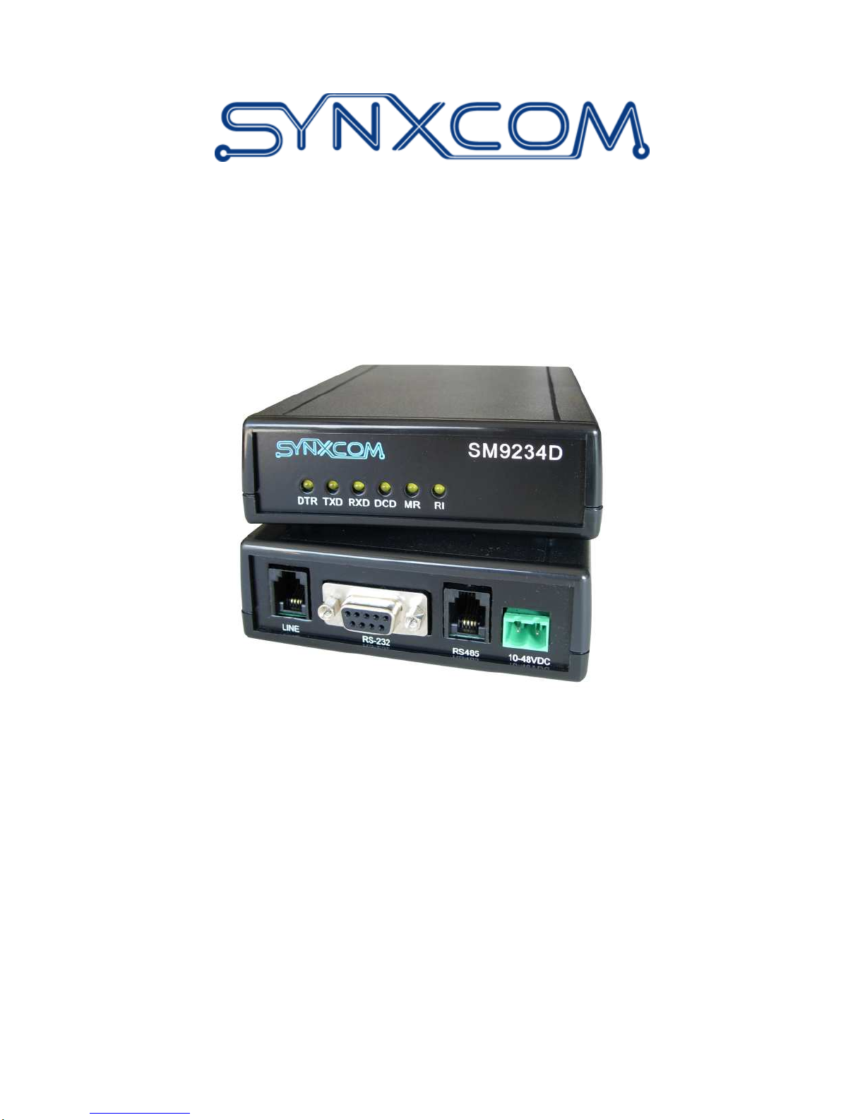
SM9256D and SM9234D Modems
User’s Guide
0049-2500-001 Rev B
Page 2

The products and programs described in this User’s Guide are licensed products of Synxcom
Corporation. This User’s Guide contains proprietary information protected by copyright, and this
User’s Guide and all accompanying hardware and documentation are copyrighted.
Synxcom Corporation does not warrant that the hardware will work properly in all environments
and applications, and makes no warranty and representation, either implied or expressed, with
respect to the quality, performance, merchantability, or fitness for a particular purpose.
Synxcom Corporation will makes best efforts to update or keep current the information in this
User’s Guide, and reserves the right to make changes to this User’s Guide and/or product without
notice.
No part of this manual may be reproduced or transmitted in any form or by any means, electronic
or mechanical, including photocopying, recording, or information storage and retrieval systems,
for any purpose other than the purchaser's personal use, without the express written permission of
Synxcom Corporation.
Copyright 2010 Synxcom Corporation.
1000 Dove Street, Suite 305
Newport Beach, California 92660
Tel: (949) 390-8236
Fax: (949) 872-2889
Web site: www.Synxcom.com
Page 3

FCC Requirements
This device complies with Part 15 Class A of the FCC Rules. Operation is subject to the following
two conditions: (1) this device may not cause harmful interference, and (2) this device must
accept any interference received, including interference that may cause undesired operation.
This equipment has been tested and found to comply with the limits for a Class A digital device,
pursuant to Part 15 Class A of the FCC Rules. These limits are designed to provide reasonable
protection against harmful interference in a residential installation. This equipment generates,
uses, and can radiate radio frequency energy and, if not installed and used in accordance with the
instructions, may cause harmful interference to radio communications. However, there is no
guarantee that interference will not occur in a particular installation. If this equipment does cause
harmful interference to radio or television reception, which can be determined by turning the
equipment off and on, the user is encouraged to try to correct the interference by one or more of
the following measures:
Reorient or relocate the receiving antenna.
Increase the separation between the equipment and the receiver.
Connect the equipment to an outlet on a circuit other than the one to which the receiver is
connected.
Consult the dealer or an experienced radio/TV technician for help.
If none of these actions resolves the problem, consult your distributor or an experienced
radio/television technician for additional suggestions.
Additionally, Section 15.838, paragraph d), of the FCC Rules and Regulations states: “Where
special accessories, such as shielded cables, are required in order to meet FCC regulations,
shielded cables must be used with this equipment. Operation with non-approved equipment or
unshielded cables is likely to result in interference to radio and TV reception. The user is
cautioned that changes and modifications to this equipment without the approval of the
manufacturer could void the user’s authority to operate this equipment.
Department of Canada Statement
This Class A digital apparatus meets all requirements of the Canadian Interference-Causing
Equipment Regulations.
Cet appareil numerique de la classe A respecte toutes les exigences du Reglement sur le materiel
brouilleur du Canada.
Page iii
Page 4

FCC Part 68 Statement
This equipment complies with the Federal Communications Commission’s (FCC) Rules and Regulations
47 CFR Part 68 and the Administrative Council on Terminal Attachments (ACTA) adopted technical
criteria TIA/EIA/IS-968, Telecommunications – Telephone Terminal Equipment – Technical Requirements
for Connection of Terminal Equipment To the Telephone Network, July 2001. On the plastic enclosure of
this equipment is a label that contains the ACTA Registration number. You must, upon request, provide
this information to your telephone company.
This equipment uses USOCs RJ11 connector.
A telephone cord and modular plug compliant with TIA/EIA/IS-968 are provided with this equipment. This
equipment is designed to be connected to the telephone network or premises wiring using a compatible
modular jack, which is Part 68 compliant. See installation instructions for details.
The REN is useful to determine the quantity of devices you may connect to your telephone line and still
have all those devices ring when your telephone number is called. In most, but not all areas, the sum of the
REN's of all devices connected to one line should not exceed five (5.0). To be certain of the number of
devices you may connect to your line, as determined by the REN, you should contact your local telephone
company to determine the maximum REN for your calling area. (NOTE: REN are associated with loopstart and ground-start ports. Do not use for E&M or digital ports).
If your telephone equipment causes harm to the telephone network, the Telephone Company may
discontinue your service temporarily. If possible, they will notify you in advance. But if advance notice is
not practical, you will be notified as soon as possible. You will be informed of your right to file a complaint
with the FCC.
Your telephone company may make changes in its facilities, equipment, operations or procedures that could
affect the proper functioning of your equipment. If they do, you will be notified in advance to give you an
opportunity to maintain uninterrupted telephone service.
If you experience trouble with this telephone equipment, please contact Synxcom Corporation, 1000 Dove
Street, Newport Beach, CA 92660, Phone (949) 677-6204 for information on obtaining service or repairs.
The telephone company may ask that you disconnect this equipment from the network until the problem has
been corrected or until you are sure that the equipment is not malfunctioning.
Please note: No user serviceable parts contains in this equipment.
This equipment may not be used on coin service provided by the telephone company. Connection to party
lines is subject to state tariffs.
The Telephone Consumer Protection Act of 1991 makes it unlawful for any person to use a computer or
other electronic device, including fax machines, to send any message unless such message clearly contains
in a margin at the top or bottom of each transmitted page or on the first page of the Transmission, the date
and time it is sent and an identification of the business or other entity, or other individual sending the
message and the telephone number of the sending machine or such business, other entity, or individual.
(The telephone number provided may not be a 900 number or any other number for which charges exceeds
Page iv
Page 5

local or long-distance transmission charges.)
Page v
Page 6

Page 7

Contents
FEATURES........................................................................................................................................................15
MODEL NUMBERS AND ORDER INFORMATION..................................................................................... 16
UNPACKING YOUR MODEM........................................................................................................................19
ADDITIONAL ITEMS YOU NEED.................................................................................................................19
SETTING-UP AND INSTALLING YOUR MODEM ......................................................................................19
INSTALLING THE DRIVER...........................................................................................................................22
WINDOWS XP...................................................................................................................................................22
WINDOWS 2000................................................................................................................................................ 22
LEDS ..................................................................................................................................................................23
MODEM OPERATION..................................................................................................................................... 23
SERIAL PORT DATA SPEED ................................................................................................................................23
AUTO-ANSWER MODE...................................................................................................................................... 23
CALL ANSWER TESTING..............................................................................................................................25
CALL ORIGINATING TESTING....................................................................................................................25
STORING TELEPHONE NUMBERS..............................................................................................................29
CONFIGURING THE $DL TIMEOUT............................................................................................................30
ENABLING THE AUTO-CONNECT FEATURE ...........................................................................................30
VIEWING THE CURRENT $DL SETTING....................................................................................................30
SYNTAX AND PROCEDURES........................................................................................................................31
ALPHABET........................................................................................................................................................ 31
DTE COMMANDS LINES....................................................................................................................................31
Command Line General Format..................................................................................................................32
Command Line Editing ...............................................................................................................................32
Command Line Echo...................................................................................................................................32
Repeating a Command Line ........................................................................................................................ 33
Types of DTE Commands............................................................................................................................33
BASIC SYNTAX COMMANDS ..............................................................................................................................33
Basic Syntax Command Format .................................................................................................................. 33
S Parameters............................................................................................................................................... 34
EXTENDED SYNTAX COMMANDS....................................................................................................................... 35
Command Naming Rules.............................................................................................................................35
Values.........................................................................................................................................................35
Action Commands....................................................................................................................................... 37
Parameter Commands................................................................................................................................. 38
Page vii
Page 8

Additional Syntax Rules.............................................................................................................................. 40
ISSUING COMMANDS.........................................................................................................................................40
EXECUTING COMMANDS ...................................................................................................................................40
Aborting Commands ................................................................................................................................... 41
Handling of Invalid Numbers and S-Parameter Values................................................................................41
MODEM RESPONSES.......................................................................................................................................... 41
Responses ...................................................................................................................................................42
Extended Syntax Result Codes ....................................................................................................................43
+<name>: <compound_value>Information Text Formats for Test Commands........................................... 45
DATA COMMAND SET...................................................................................................................................47
COMMAND GUIDELINES.................................................................................................................................... 47
Escape Code Sequence ............................................................................................................................... 47
DATA COMMANDS............................................................................................................................................47
Generic Modem Control .............................................................................................................................47
Z - Soft Reset and Restore Profile ............................................................................................................... 47
+FCLASS - Select Active Service Class ...................................................................................................... 48
+VCID - Caller ID (CID)............................................................................................................................49
+VRID - Report Retrieved Caller ID (CID)................................................................................................. 49
\N - Operating Mode................................................................................................................................... 50
I - Identification..........................................................................................................................................50
+GMI - Request Manufacturer Identification..............................................................................................51
+GMI9 - Request Conexant Identification...................................................................................................51
+GMM - Request Model Identification ....................................................................................................... 52
+GMR - Request Revision Identification..................................................................................................... 52
+GCAP - Request Complete Capabilities List.............................................................................................52
+GCI - Country of Installation....................................................................................................................52
&F - Restore Factory Configuration (Profile) ............................................................................................. 53
&T - Local Analog Loopback Test............................................................................................................... 54
&Y - Designate a Default Reset Profile....................................................................................................... 54
&W - Store Current Configuration.............................................................................................................. 54
&Zn=x - Store Telephone Number ..............................................................................................................54
%7 - Plug and Play Serial Number..............................................................................................................55
%8 - Plug and Play Vendor ID and Product Number................................................................................... 55
**- Load Flash Memory..............................................................................................................................55
DTE-Modem Interface Commands .............................................................................................................. 58
E - Command Echo..................................................................................................................................... 58
Q - Quiet Results Codes Control.................................................................................................................58
V - Result Code Form.................................................................................................................................. 58
W - Connect Message Control..................................................................................................................... 59
X - Extended Result Codes.......................................................................................................................... 59
&C - RLSD (DCD) Option .......................................................................................................................... 63
&D - DTR Option........................................................................................................................................64
&K - Flow Control...................................................................................................................................... 65
&M - Asynchronous/Synchronous Mode Selection.......................................................................................65
&Q - Sync/Async Mode............................................................................................................................... 66
&R - RTS/CTS Option................................................................................................................................. 67
&S - DSR Override ..................................................................................................................................... 67
&X - Select Synchronous Clock Source....................................................................................................... 67
+IPR - Fixed DTE Rate ..............................................................................................................................68
+IFC - DTE-Modem Local Flow Control....................................................................................................69
+ILRR - DTE-Modem Local Rate Reporting ............................................................................................... 69
Call Control................................................................................................................................................ 70
T - Set Tone Dial Default .....................................................................................................................................72
Page viii
Page 9

P - Set Pulse Dial Default........................................................................................................................... 72
A - Answer..................................................................................................................................................73
H - Disconnect (Hang-Up).......................................................................................................................... 73
O - Return to On-Line Data Mode...............................................................................................................74
L - Speaker Volume..................................................................................................................................... 74
M - Speaker Control ...................................................................................................................................74
&G - Select Guard Tone..............................................................................................................................75
&P - Select Pulse Dial Make/Break Ratio ................................................................................................... 75
&V - Display Current Configuration and Stored Profiles ............................................................................ 75
&V1 - Display Last Connection Statistics....................................................................................................76
\V - Single Line Connect Message Enable ................................................................................................... 77
%L - Report Line Signal Level .................................................................................................................... 78
%Q - Report Line Signal Quality................................................................................................................. 78
*B - Display Blacklisted Numbers............................................................................................................... 79
–PPD= - Extension Pickup Notification through 16550 UART.................................................................... 79
–STE= - Set Telephony Extension ............................................................................................................... 79
Modulation Control Commands ..................................................................................................................86
+MS - Modulation Selection ....................................................................................................................... 86
+MR - Modulation Reporting Control.........................................................................................................89
+MCR: Report Syntax.................................................................................................................................89
+MRR: Report Syntax.................................................................................................................................90
%E - Enable/Disable Line Quality Monitor and Auto-Retrain or Fallback/Fall........................................... 90
%U - Select µ-Law or A-Law Codec Type.................................................................................................... 91
B - CCITT or Bell ....................................................................................................................................... 91
Error Control Command.............................................................................................................................92
+ES - Error Control and Synchronous Mode Selection ............................................................................... 92
+EB - Break Handling in Error Control Operation.....................................................................................93
+ESR - Selective Repeat .............................................................................................................................94
+EFCS - 32-bit Frame Check Sequence......................................................................................................94
+ER - Error Control Reporting................................................................................................................... 94
+ER: <value> ............................................................................................................................................95
+ER: <type>..............................................................................................................................................95
+ETBM - Call Termination Buffer Management .........................................................................................95
\B - Transmit Break to Remote.................................................................................................................... 96
\K - Break Control...................................................................................................................................... 96
-K - MNP Extended Services.......................................................................................................................97
3.2.6 Data Compression Commands.......................................................................................................98
+DS - Data Compression............................................................................................................................98
+DS44 - V.44 Compression Select .............................................................................................................. 98
+DR - Data Compression Reporting ......................................................................................................... 100
+DR: <type> Intermediate Result Code ................................................................................................... 100
%C - Enable/Disable Data Compression................................................................................................... 101
V.8/V.8bis Commands............................................................................................................................... 101
+A8E - V.8 and V.8bis Operation Controls............................................................................................... 101
+A8I: - CI Signal Indication.....................................................................................................................102
Synchronous Access Mode Commands ...................................................................................................... 103
+ESA - Configure Synchronous Access Submode...................................................................................... 103
+H - Enable/Disable RPI.......................................................................................................................... 104
+ITF - Transmit Flow Control Thresholds................................................................................................. 105
Diagnostic Commands .............................................................................................................................. 106
#UD – Last Call Status Report.................................................................................................................. 106
Compatibility Commands.......................................................................................................................... 115
&L - Leased Line Operation......................................................................................................................115
)M - Enable Cellular Power Level Adjustment .......................................................................................... 115
Page ix
Page 10

@M - Initial Cellular Power Level Setting ................................................................................................115
:E - Compromise Equalizer Enable Command .......................................................................................... 116
FastConnect Commands............................................................................................................................ 116
$F – FastConnect Control......................................................................................................................... 116
V.92 +P and –Q Commands...................................................................................................................... 117
+PCW - Call Waiting Enable.................................................................................................................... 117
+PMH - Modem-on-Hold Enable.............................................................................................................. 117
+PMHT – Modem-on-Hold Timer............................................................................................................. 118
+PMHR - Initiate Modem-on-Hold ........................................................................................................... 118
+PIG - PCM Upstream Ignore.................................................................................................................. 119
+PMHF - V.92 Modem-on-Hold Hook Flash ............................................................................................ 119
+PQC - V.92 Phase 1 and Phase 2 Control............................................................................................... 120
+PSS - Use Short Sequence....................................................................................................................... 120
-QCPC - Force Full Startup Procedure Next Connection..........................................................................121
-QCPS - Enable Quick Connect Profile Save ............................................................................................ 121
S-PARAMETERS ..............................................................................................................................................122
FACTORY DEFAULTS............................................................................................................................. 123
S-PARAMETER DEFINITIONS ................................................................................................................ 125
S0 - Number of Rings to Auto-Answer....................................................................................................... 125
S1 - Ring Counter..................................................................................................................................... 125
S2 - Escape Character.............................................................................................................................. 125
S3 - Carriage Return Character................................................................................................................ 125
S4 - Line Feed Character.......................................................................................................................... 125
S5 - Backspace Character......................................................................................................................... 126
S6 - Wait Time before Blind Dialing or for Dial Tone............................................................................... 126
S7 - Wait Time for Carrier, Silence, or Dial Tone..................................................................................... 126
S8 - Pause Time For Dial Delay................................................................................................................ 127
S9 - Carrier Detect Response Time ...........................................................................................................127
S10 - Lost Carrier To Hang Up Delay....................................................................................................... 127
S11 - DTMF Tone Duration ...................................................................................................................... 128
S12 - Escape Prompt Delay (EPD)............................................................................................................ 128
S14 - General Bit Mapped Options Status ................................................................................................. 128
S16 - Test Mode Bit Mapped Options Status.............................................................................................. 129
S19 – Reserved ......................................................................................................................................... 129
S20 – Reserved ......................................................................................................................................... 129
S21 - V.24/General Bit Mapped Options Status......................................................................................... 129
S22 - Speaker/Results Bit Mapped Options Status..................................................................................... 130
S23 - General Bit Mapped Options Status ................................................................................................. 130
S24 - Sleep Inactivity Timer ...................................................................................................................... 130
S25 - Delay To DTR Off............................................................................................................................ 130
S26 - RTS to CTS Delay............................................................................................................................ 131
S27 - Bit Mapped Options Status...............................................................................................................131
S28 - Bit Mapped Options Status...............................................................................................................131
S29 - Flash Dial Modifier Time.................................................................................................................132
S30 - Disconnect Inactivity Timer ............................................................................................................. 132
S31 - Bit Mapped Options Status...............................................................................................................132
S36 - LAPM Failure Control..................................................................................................................... 133
S38 – Delay Before Forced Hang up......................................................................................................... 133
S39 - Flow Control Bit Mapped Options Status......................................................................................... 133
S40 - General Bit Mapped Options Status ................................................................................................. 134
S41 - General Bit Mapped Options Status ................................................................................................. 134
S46 - Data Compression Control............................................................................................................... 134
S48 - V.42 Negotiation Control................................................................................................................. 135
S48=7 Enable negotiation. (Default.)................................................................................................. 135
Page x
Page 11

S86 - Call Failure Reason Code................................................................................................................ 135
S86=11 No sync information from the remote modem. ......................................................................... 135
S86=26 Remote hangup detected. ........................................................................................................ 136
S91 - PSTN Transmit Attenuation Level .................................................................................................... 137
S92 - Fax Transmit Attenuation Level ....................................................................................................... 137
S95 - Extended Result Codes Control........................................................................................................ 137
S210 – V.34 Symbol Rates......................................................................................................................... 138
CELLULAR COMMANDS...................................................................................................................................138
Cellular Phone Drivers............................................................................................................................. 139
Cellular Commands .................................................................................................................................. 139
^C2 - Download Cellular Phone Driver .................................................................................................... 139
^I - Identify Cellular Phone Driver ........................................................................................................... 139
^T6 - Indicate Status of Cellular Phone..................................................................................................... 140
Operation ................................................................................................................................................. 140
RESULT CODES............................................................................................................................................... 144
FAX CLASS 1 AND FAX CLASS 1.0 COMMANDS ..................................................................................... 149
FAX I/O PROCESSING ...................................................................................................................................... 149
DTE-to-Modem Transmit Data Stream...................................................................................................... 149
Modem-to-DTE Receive Data Stream ....................................................................................................... 149
Fax Mode Selection .................................................................................................................................. 149
Fax Origination ........................................................................................................................................ 150
Fax Answering.......................................................................................................................................... 151
Fax Control Transmission......................................................................................................................... 151
Fax Control Reception.............................................................................................................................. 151
Fax Data Transmission............................................................................................................................. 153
Fax Data Reception .................................................................................................................................. 153
COMMANDS AND PARAMETERS........................................................................................................................ 154
Mode Entry Commands.............................................................................................................................154
+FCLASS=1 - Select Facsimile Class 1 Mode .......................................................................................... 154
+FCLASS=1.0 - Select Facsimile Class 1.0 Mode..................................................................................... 154
Mode Commands ...................................................................................................................................... 155
+FAA - Auto Answer Enable.....................................................................................................................155
+FAE - Auto Answer Enable.....................................................................................................................155
+FTS - Transmit Silence ........................................................................................................................... 155
+FRS - Receive Silence............................................................................................................................. 156
+FTM – Transmit Facsimile ..................................................................................................................... 156
+FRM - Receive Facsimile ....................................................................................................................... 158
+FTH - Transmit Data with HDLC Framing............................................................................................. 158
+FRH - Receive Data with HDLC Framing .............................................................................................. 159
Service Class 1 Parameters....................................................................................................................... 160
+FAR - Adaptive Reception Control ......................................................................................................... 160
+FCL - Carrier Loss Timeout ................................................................................................................... 160
+FDD - Double Escape Character Replacement.......................................................................................161
+FIT - DTE Inactivity Timeout ................................................................................................................. 161
+FPR - Fixed DTE Rate ........................................................................................................................... 162
+FMI? - Request Manufacturer Identification .......................................................................................... 163
+FMM? - Request Model Identification.................................................................................................... 163
+FMR? - Request Revision Identification ................................................................................................. 163
+FLO - Flow Control................................................................................................................................ 163
EXAMPLES...................................................................................................................................................... 164
FAX CLASS 2 COMMANDS.......................................................................................................................... 167
COMMAND AND SYNTAX GUIDELINES.............................................................................................................. 168
Page xi
Page 12

Mode Entry Commands.............................................................................................................................168
+FCLASS=2 - Select Facsimile Class 2 Mode .......................................................................................... 168
DTE Commands........................................................................................................................................ 168
Serial Port Speed and Flow Control.......................................................................................................... 170
Auto Answer.............................................................................................................................................. 171
Identification of T.30 Options ................................................................................................................... 171
Session Status Reporting........................................................................................................................... 171
Procedure Interrupt Negotiation ............................................................................................................... 172
SERVICE CLASS 2 IDENTIFICATION AND SELECTION.......................................................................................... 172
+FMFR? - Request Manufacturer Identification ....................................................................................... 172
+FMDL? - Identify Product Model ........................................................................................................... 172
+FREV? - Identify Product Revision......................................................................................................... 172
SERVICE CLASS 2 ACTION COMMANDS ............................................................................................................ 173
ATD - Originate a Call ............................................................................................................................. 173
ATA - Answer a Call ................................................................................................................................. 174
+FDT - Data Transmission....................................................................................................................... 175
+FET - Transmit Page Punctuation .......................................................................................................... 178
+FDR - Begin or Continue Phase C Receive Data.................................................................................... 179
+FK - Session Termination ....................................................................................................................... 181
+FCIG - Set Polling ID.............................................................................................................................181
+FLPL - Indicate a Document for Polling................................................................................................. 181
+FSPL - Enable Polling............................................................................................................................182
SERVICE CLASS 2 DCE RESPONSES.................................................................................................................. 183
+FCON - Facsimile Connection Response................................................................................................ 183
+FDCS: - Report Current Session Capabilities......................................................................................... 183
+FDIS: - Report Remote Station Capabilities........................................................................................... 183
+FCFR - Indicate Confirmation to Receive............................................................................................... 184
+FTSI: - Report the Transmit Station ID...................................................................................................184
+FCSI: - Report the Called Station ID...................................................................................................... 184
+FPTS: - Receive Page Transfer Status ....................................................................................................184
+FET: - Post Page Message Response...................................................................................................... 185
+FPTS: - Transmit Page Transfer Status...................................................................................................185
+FHNG: - Call Termination with Status ................................................................................................... 185
+FCIG: - Report the Polled Station ID ..................................................................................................... 185
+FDTC: - Report the Polled Station Capabilities......................................................................................186
+FPOLL - Indicate Polling Request.......................................................................................................... 186
SERVICE CLASS 2 PARAMETERS....................................................................................................................... 186
+FDCC - DCE Capabilities Parameters................................................................................................... 186
+FDIS - Current Sessions Capabilities Parameters................................................................................... 186
+FDCS - Current Session Results Parameters........................................................................................... 187
+FLID= - Local ID String ........................................................................................................................ 188
+FCR - Capability to Receive................................................................................................................... 188
+FPTS= - Page Transfer Status................................................................................................................ 188
+FCQ - Copy Quality Checking................................................................................................................ 190
+FPHCTO - DTE Phase C Response Time-out ......................................................................................... 190
+FAXERR - T.30 Session Error Report..................................................................................................... 190
+FBOR - Data Bit Order .......................................................................................................................... 190
+FAA - Answer Parameter........................................................................................................................ 191
+FBUF? - Buffer Size............................................................................................................................... 191
EXAMPLE SESSIONS ........................................................................................................................................192
VOICE COMMANDS...................................................................................................................................... 194
VOICE COMMANDS OVERVIEW........................................................................................................................ 194
<DLE> Shielded Event Codes Sent to the DTE.................................................................................................. 195
Page xii
Page 13

<DLE> Shielded Codes Sent to the Modem (DCE) ................................................................................... 196
VOICE COMMANDS......................................................................................................................................... 196
Configuration Commands ......................................................................................................................... 196
+FCLASS=8 - Select Voice Mode ............................................................................................................. 196
+VNH - Automatic Hang-up Control.........................................................................................................196
Voice Commands ...................................................................................................................................... 197
+VIP - Voice Initialize All Parameters...................................................................................................... 197
+VRX - Start Modem Receive (Record)..................................................................................................... 197
+VTS - Send Voice Tone(s) ....................................................................................................................... 199
+VTX - Start Modem Transmit (Playback) ................................................................................................ 201
+VGR - Voice Gain Receive (Record Gain) .............................................................................................. 201
+VGT - Voice Gain Transmit (Playback Volume)...................................................................................... 202
+VIT - Voice Inactivity Timer (DTE/Modem)............................................................................................202
+VLS - Analog Source/Destination Selection ............................................................................................ 202
+VRA - Ringback Goes Away Timer..........................................................................................................206
+VRN - Ringback Never Appeared Timer ................................................................................................. 206
+VSD - Silence Detection (Quiet and Silence) .......................................................................................... 207
+VSM - Compression Method Selection.................................................................................................... 208
+VTD - Beep Tone Duration Timer........................................................................................................... 209
+VDR - Distinctive Ring...........................................................................................................................209
+VDT - Control Tone Cadence Reporting................................................................................................. 210
+VPR - Select DTE/Modem Interface Rate (Turn Off Autobaud)............................................................... 210
Speakerphone Commands ......................................................................................................................... 211
+VSP - Speakerphone ON/OFF................................................................................................................. 211
+VDX - Speakerphone Duplex Mode ........................................................................................................ 211
+VGM - Microphone Gain........................................................................................................................ 212
+VGS - Speaker Gain ...............................................................................................................................212
Page xiii
Page 14

Page 15

Chapter 1
Introduction
he Synxcom SM9256D and SM9234D are industrial grade standalone data/fax modem that
deliver outstanding performance, transmitting data at the highest rates available over the
T
public switched telephone networks (PSTN) today. The SM9256D, supports V.92 & V34
standards, offers asynchronous line speeds of up to 56kbps. The SM9234D supports V.34 and
line speeds of up to 33.6kbps. Both modems incorporate the latest data compression and error
correction standards and are capable of providing data throughput up to 230.4 kbps. The
SM9256D and SM9234D incorporate advanced technology that enhances operation on less-thanideal transmission lines. Both modems also offer optional security features ideal for personal and
corporate applications. The SM9256D easily handles tasks such as remote LAN access,
telecommuting, remote file transfer, access to the Internet, and any other applications that require
fast, reliable transmission speeds.
Features
2-wire unconditioned dial-up telephone line
Build with industrial grade components to meet and operate under harsh environment
ITU-V.92 capabilities, (model SM9256D)
Compatible with ITU V.34, V.32bis, V.32, V.29, V.27ter, V.23, V.22bis, V.21, and V.17
Maximum throughput may be up to 230.4KBPS using data compression
Supports industry-standard AT command set
Supports V.42 and MNP 2-4 error correction and V.42bis and MNP5 data compression
Support RS-232 and RS-485 serial interface (user selectable)
Support DC or battery powered operation by an isolated 10 to 60 VDC power supply
Optional mounting kits for DIN rail mounting and wall/panel mounting
Page 15
Page 16
Model Numbers and Order Information
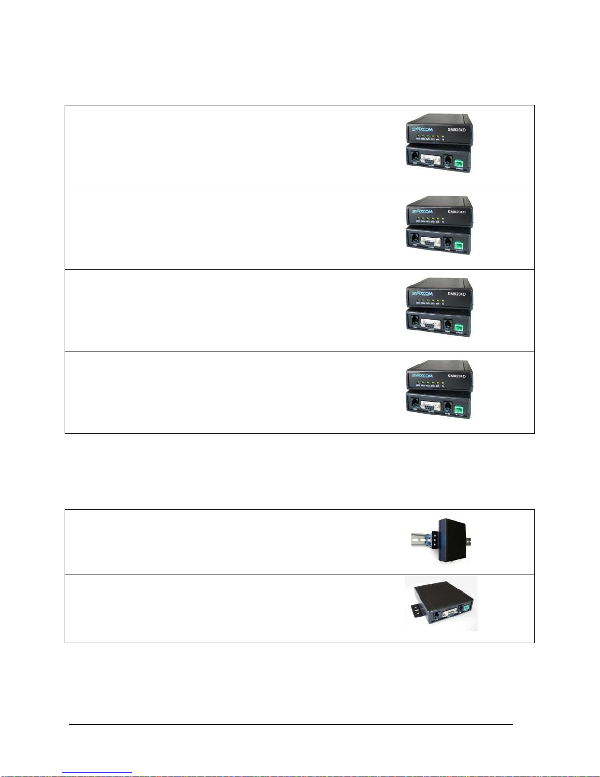
Model SM9256D:
V92/V34/V32bis/V32/V22bis (56K)
Stand-alone with AC power module
90 to 264 VAC or 100-400 VDC
Model SM9256D-DC:
V92/56K/V34/V32bis/V32/V22bis
Stand-alone, DC power, 10-48 VDC
Model SM9234D:
V34/V32bis/V32/V22bis (33.6K)
Stand-alone with AC power module
90 to 264 VAC or 100-400 VDC
Introduction
Model SM9234D-DC:
V34/V32bis/V32/V22bis (33.6K)
Stand-alone, DC power, 10-48 VDC
Mounting kit Accessories
EN2-KIT-DIN:
DIN Rail Mounting Kit for S/A units
EN2-KIT-WMB:
Wall-Panel mounting kit for S/A units
Page 16
Page 17

Introduction
Page 17
Page 18

Page 19

Chapter 2
Installation
Unpacking Your Modem
Your SM9256D/SM9234D modem package includes the following items:
One Synxcom SM9256D or SM9234D standalone modem
An RJ-11 telephone cable
An 115/230VAC AC to DC power supply converter (for SM9256D and SM9234D)
A DC power cable (for the SM9256D-DC and SM9234D-DC versions)
A CD containing the modem User’s Guide
Additional Items You Need
To install the SM9256D/SM9234D modems, you need the following additional items:
The power source that matches the model you order, AC power module or 10-48VDC.
A standard wall-mounted telephone jack (RJ-11C) located within 6 feet of your computer
For RS-232 interface, a shielded serial cable with a 9-pin male connector for connecting to
your SM9256D/SM9234D. The connector on the other end of the cable should match the
requirements of your computer or Data Terminal Equipment (DTE).
For RS-485/RS-422 interface, a RJ-11 serial cable connected to your RTU or DTE is required
Note: If you use fax software, be sure it supports Class 1 fax operation.
Setting-up and Installing Your Modem
Configuring Your Modem’s DTE/RTU Interface.
Page 19
Page 20
Installation
Your SM9256D and SM9234D support RTU/DTE with either RS-232 or RS-485 interface for
communications. The modem is set to use the RS-232 interface (DB-9 connector) as the default
interface from the factory. If you do not use RS-485/RS-422 option of the modem, skip this
section and continue the installation with the “Installing Your Modem” section below.
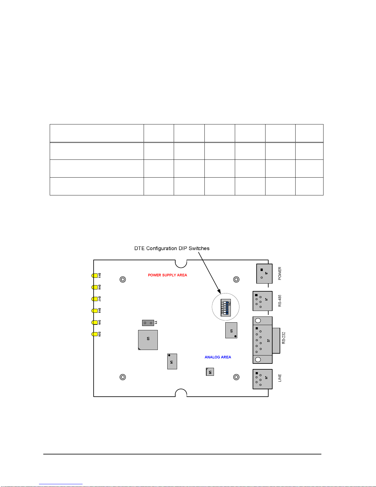
To configure the modem for RS-485/RS-422 interface, you will need to connect your DTE/RTU
to the RJ-11 connector as shown in Fig. 1 below and set up the DTE configuration DIP switches
(SW1) provided on the modem PCB as indicated in the table below.
DTE/RTU Interface SW-1 SW-2 SW-3 SW-4 SW-5 SW-6
RS-232 (DB-9) (default)
RS-485 4-wire full duplex
RS-485 2-wire half duplex
OFF OFF OFF OFF OFF OFF
ON ON ON OFF OFF ON
OFF ON OFF ON ON OFF
Note: Use a sharp pin to push and slide the DIP switches to the side labeled “ON” on the DIP
switch is equivalent to CLOSE the switch.
Figure 1 Configuration DIP Switch
Page 20
Page 21
Installation
Installing Your Modem
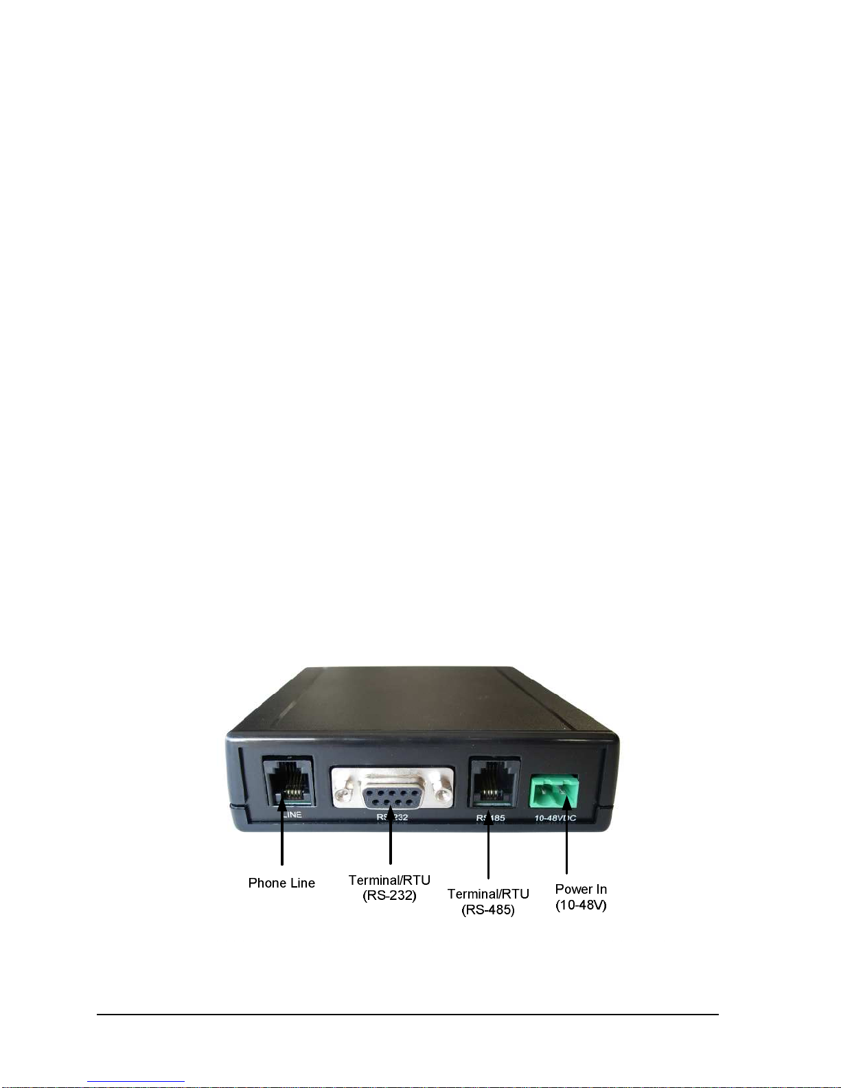
The following procedure describes how to install your SM9256D modem. You perform these
procedures using the connectors and jacks on the back of your SM9256D modem (see Fig. 2 on
page 17).
1. Turn off your computer.
2. Disconnect the power connector on the back of your SM9256D modem.
3. Connect one end of the DTE-DCE cable (no cross over cable) to your computer. Connect the
other end of the cable to the DB-9 female connector on the back of your SM9256D modem.
4. Connect either end of the supplied RJ-11 cable to a telephone wall jack. Connect the other
end of the cable to the WALL jack on the back of your SM9256D modem.
5. Connect the AC to DC power supply module to the modem. If DC power source is used,
make sure the voltage range is within 10 to 48VDC.
6. Proceed to “Installing the Driver ” on the next page.
Figure 2. SM9256D Modem Back Panel
Page 21
Page 22

Installation
Installing the Driver
After you install your SM9256D, use the appropriate procedure to install the modem driver. The
driver is supplied on the CD that came with your SM9256D modem.
Windows XP
If your computer contains the Microsoft Windows XP operating system, use the following
procedure to install the modem driver.
1. Windows detects your SM9256D modem automatically.
2. In your computer’s CD-ROM drive, insert the supplied driver CD.
3. Click Install the software automatically [Recommended] if it’s not selected and click Next.
4. If a window tells you that the software you are installing for this hardware has not passed
Windows Logo testing, click Continue Anyway. Windows installs the modem driver.
5. When the Completing the Found New Hardware Wizard appears, click Finish to complete the
driver-installation procedure.
Windows 2000
If your computer contains the Microsoft Windows 2000 operating system, use the following
procedure to install the modem driver.
1. Windows detects your SM9256D modem automatically.
2. In your computer’s CD-ROM drive, insert the supplied driver CD.
3. Click Search for a suitable driver for my device [recommended] if it’s not selected and
click Next.
4. Under Optional Search Locations, check CD-ROM drives if it is not checked and click
Next. The Found New Hardware Wizard finds the driver for your modem.
5. Click Next to start the driver installation.
6. If a window tells you that the software you are installing for this hardware has not passed
Windows Logo testing, click Yes to continue the installation. Windows installs the modem
driver.
7. When the Completing the Found New Hardware Wizard appears, click Finish to complete the
driver-installation procedure.
Page 22
Page 23

Installation
LEDs
The SM9256D modem provides six LED indicators. Table 2-6 lists the modem LED indicators.
Table 2-6. LEDs Indicating Modem Control Signals
LED DTE Signal
DTR
TD
RD
DCD
MR
RI
Data Terminal Ready
Transmitted Data
Received Data
Data Carrier Detect
Modem Ready
Ring Indicator
Modem Operation
Before you start using the modem, you must set up the modem to match your DTE&RTU
configurations. Parameters such as the following are important to consider:
• Serial port data speed when originate a connection or answering a call
• Method for the DTE to originate a call (AT dial string or DTR signaling, etc,)
• Enable or disable the auto-answer mode when a ring signal is received
• Flow control for your DTE or RTU, if any is used
Serial Port Data Speed
The modem is set to auto-speed detect (auto baud) in default mode. When a AT string is
received, it will set its speed and character format automatically to match the terminal speed until
the power is recycled or reset. If the modem is in answering mode only, it is necessary to
configure the DTE speed to match with the connected DTE such that proper communications will
take place once it auto-answer an incoming call. Please refer to commands for AT+IPR for
further details.
Auto-Answer Mode
By default, the SM9256D modem is set up to not auto-answer incoming calls. If you want the
modem to answer calls automatically, set the S0 register to a value other than its default value of
zero. For example, issuing the AT command ATS0=1 configures the modem to auto-answer
Page 23
Page 24

Installation
calls after the first ring. These commands are typed from your computer or DTE keyboard using
terminal-emulation software such as HyperTerminal.
If you change the auto-answer parameter, the new setting remains in effect until your modem is
powered-off. The next time your modem is powered-up, auto-answer is disabled again. To keep
auto-answer enabled each time the modem is powered-up, use the AT&W command to save your
changes in the modem’s nonvolatile memory. For more information about using this command to
store AT commands in nonvolatile memory, refer to the &W command on page 54.
Page 24
Page 25

Installation
Call Answer Testing
After powering-on the SM9256D modem, use the following procedure to test the modem’s ability
to answer a call.
1. Configure your SM9256D modem to auto-answer incoming calls, as described under “Modem
Operation” on page 13.
2. Use a telephone to call the SM9256D modem. Listen to the call to verify that the SM9256D
modem answers the call with its answer tone and performs its handshaking sequence in an
attempt to make a data connection. Hang up the handset of the telephone that originated the
call.
3. Use another modem to call the SM9256D modem. Verify that the SM9256D modem answers
the call, makes a data connection, and turns on the MR and DCD LEDs.
Call Originating Testing
Use the following procedure to test the modem’s ability to place a call.
1. Using terminal-emulation software such as HyperTerminal, issue the AT command
ATD<your number> where <your number> is the telephone number your modem is
connected to. For example, if your modem is connected to the line 555-1212, type
ATD5551212.
2. You should hear the modem originate the call followed by a busy signal (since the modem is
dialing its own number). In addition, a BUSY result code should appear on the computer or
DTE monitor.
If you do not hear the modem placing the call, use the ATL and ATM commands to adjust the
volume and status of the modem speaker. For more information about these commands, refer to
page 74.
Note: If you try to establish a V.90 or V.92 connection, be sure the remote modem also
supports V.90 or V.92. Otherwise, you will not be able to establish the connection.
Page 25
Page 26

Page 27

Using the Modem’s Auto-Connect Feature
Chapter 3
Using the Modem’s Security Features
This section is available with the security modems only
Page 27
Page 28

Using the Modem’s Auto-Connect Feature
Page 28
Page 29

Using the Modem’s Auto-Connect Feature
Chapter 4
Using the Modem’s Auto-Connect
Feature
Your SM9256D modem can emulate a leased-line connection over the Public Switched
Telephone Network (PSTN). Using the $DL command, you can configure the modem to work
similarly to the “always connected” functionality used with leased lines. This feature is useful in
environments where a leased line is not available or is cost prohibitive. In certain environments,
this feature is more robust in recovering from network failures.
When the $DL command is used, your SM9256D modem automatically dials the first of four
telephone numbers you have stored using the &Zn=x command. If the call fails or is
disconnected, your modem waits a user-defined number of seconds before redialing the number. If
the redialing attempt fails to make a connection (for example, if the number dialed is busy or the
called modem does not answer), your modem automatically dials the next number stored with the
&Zn=x command. The modem repeats this round-robin method until a dialed number results in a
data connection.
Storing Telephone Numbers
Before you use the &Zn=x command, store up to four telephone numbers in your modem’s
nonvolatile memory. These are the telephone numbers your modem automatically dials when it
executes an $DL command.
In the command &Zn=x, n is a decimal number from 0 to 3 that corresponds to a location in the
modem’s nonvolatile memory and x is a dial string up to 31 characters long. The following
examples show how to store sample dial strings in the modem’s nonvolatile memory.
Example Description
AT&Z0=5551212 Stores dial string 5551212 in nonvolatile memory location 0.
AT&Z1=9,19495551234 Stores dial string 9,19495551234 in nonvolatile memory location 1.
AT&Z2=T9,P5552468 Stores dial string AT&Z2=T9,P5552468 in nonvolatile memory
location 2.
Page 29
Page 30

Using the Modem’s Auto-Connect Feature
AT&Z3=9,5552468 Stores dial string AT&Z3=9,5552468 in nonvolatile memory
location 2.
Configuring the $DL Timeout
The $DL timeout determines how long your modem waits between dialing attempts when a call
dialed with the $DL command does not establish a data connection with the remote modem. This
timeout value is controlled by Register S32. By default, Register S32 is set to 30 seconds. If
desired, you can increase or shorten this timeout value. To change this default value, type the
following command line and press the Enter key.
ATS32=n where n is the number of seconds the modem is to wait, from 1 to 255. Entering a
value of 0 specifies the default timeout value of 30 seconds.
Enabling the Auto-Connect Feature
To enable the auto-connect feature, type AT$DLON and press Enter. When you enable this
feature, your modem automatically dials the dial string in nonvolatile memory position 0. If your
modem fails to make a data connection, it waits the $DL timeout time specified by Register S32,
then automatically dials the dial string stored in the next nonvolatile memory position. Your
modem continues this round-robin s until it makes a data connection with a remote modem.
If the remote modem disconnects, your modem automatically redials the number of the previous
connection. If that dialing attempt fails to make a connection, your modem dials the dial string
stored in the next nonvolatile memory positions until it makes a data connection with a remote
modem. The modem repeats this round-robin method until a dialed number results in a data
connection.
To disable the auto-connect feature, type AT$DLOFF and press Enter.
Viewing the Current $DL Setting
To view the current setting of the $DL command, type AT$DL? And press Enter.
If auto-connect is enabled, your modem responds with: ON
If auto-connect is disabled, your modem responds with: OFF
Page 30
Page 31

AT Commands
Appendix A
AT Commands
Syntax and Procedures
The command and response syntax and procedures generally conform to referenced
recommendations and standards. Since these recommendations and standards describe
characteristics universal to a large installed base of modems to a maximum degree, there may be
syntax and procedural differences due to extensions and behavioral differences in implemented
commands, parameters, and responses beyond that described in these recommendations and
standards.
The syntax and procedures described in this appendix are based on V.250 and V.253 with
additional information included for implemented extensions, behavioral differences beyond V.250,
and legacy commands.
Alphabet
The T.50 International Alphabet 5 (IA5) is used in this document. Only the low-order seven bits
of each character are significant to the modem; any eighth or higher-order bit(s), if present, are
ignored for the purpose of identifying commands and parameters. Lower-case characters are
considered identical to their upper-case equivalents when received by the modem from the DTE.
Result codes from the modem are in upper case.
DTE Commands Lines
Words enclosed in <angle brackets> are references to syntactical elements. The brackets are not
used when the words appear in a command line, the brackets are not used. Words enclosed in
[square brackets] represent optional items which may be omitted from the command line at the
specified point. The square brackets are not used when the words appear in the command line.
Other characters that appear in syntax descriptions must as included as shown. Any modem
responses are mentioned in terms of their alphabetic format; the actual response issued will
depend on the setting of parameters that affect response formats, e.g., Q and V commands (see
2.7).
Page 31
Page 32

Command Line General Format
A command line is made up of three elements: the prefix, the body, and the
termination character.
The command line prefix consists of the characters "AT" or "at". To repeat the
execution of the previous command line, the characters "A/" or "a/" are used
without typing the command line prefix.
The body is made up of individual commands described in this document. Space
characters (IA5 2/0) are ignored and may be used freely for formatting purposes,
unless they are embedded in numeric or string constants. The termination character
may not appear in the body. The modem can accept at least 50 characters in the
body.
The termination character may be selected by a user option (parameter S3), the
default being CR.
Command Line Editing
AT Commands
The character defined by parameter S5 (default, BS) is interpreted as a request
from the DTE to the modem to delete the previous character. Any control
characters (IA5 0/0 through 1/15, inclusive) that remain in the command line after
receipt of the termination character are ignored by the modem.
The modem checks characters from the DTE first to see if they match the
termination character (S3), then the editing character (S5), before checking for
other characters. This ensures that these characters will be properly recognized
even if they are set to values that the modem uses for other purposes. If S3 and S5
are set to the same value, a matching character will be treated as matching S3 (S3
is checked before S5).
Command Line Echo
The modem may echo characters received from the DTE during command state
and online command state back to the DTE, depending on the setting of the E
command. If enabled, characters received from the DTE are echoed in the same
format as received. Invalid characters in the command line or incomplete or
improperly formed command line prefixes may not be echoed.
Page 32
Page 33

Repeating a Command Line
If the prefix "A/" or "a/" is received, the modem immediately executes once again
the body of the preceding command line. No editing is possible, and no termination
character is necessary. A command line may be repeated multiple times in this
manner.
Responses to the repeated command line are issued using format of the original
command line. If "A/" is received before any command line has been executed, the
preceding command line is assumed to have been empty (that results in an OK
result code).
Types of DTE Commands
There are two types of commands: action commands and parameter commands.
Commands of either type may be included in command lines, in any order.
AT Commands
Action commands may be "executed" (to invoke a particular function of the
equipment, which generally involves more than the simple storage of a value for
later use), or "tested" (to determine whether or not the equipment implements the
action command, and, if sub parameters are associated with the action, the ranges
of sub parameter values that are supported).
Parameters may be "set" (to store a value or values for later use), "read" (to
determine the current value or values stored), or "tested" (to determine whether or
not the equipment implements the parameter, and the ranges of values supported).
Basic Syntax Commands
Basic Syntax Command Format
The format of Basic Syntax commands, except for the D and S commands, is as
follows:
<command>[<number>]
where <command> is either a single character, or the "&" character followed by a
single character per V.250. In addition, <command> can be the "%" character
followed by a single character, the "*" character followed by a single character, or
the "^" character followed by a single character.
Page 33
Page 34

<number> may be a string of one or more characters from "0" through "9"
representing a decimal integer value. Commands that expect a <number> are
noted in the description of the command. If a command expects <number>and it is
missing (<command> is immediately followed in the command line by another
<command> or the termination character), the value "0" is assumed. If a
command does not expect a <number> and a number is present, an ERROR is
generated. All leading "0"s in <number> are ignored by the modem.
Additional commands may follow a command (and associated parameter, if any)
on the same command line without any character required for separation. The
actions of some commands cause the remainder of the command line to be ignored
(e.g., A).
See the D command for details on the format of the information that follows it.
S Parameters
Commands that begin with the letter "S" are known as "S-parameters". The
number following the "S" indicates the "parameter number" being referenced. If
the number is not recognized as a valid parameter number, an ERROR result code
is issued.
AT Commands
Immediately following this number, either a "?" or "=" character must appear. "?"
is used to read the current value of the indicated S-parameter; "=" is used to set
the S-parameter to a new value.
S<parameter_number>?
S<parameter_number>=[<value>]
If the "=" is used, the new value to be stored in the S-parameter is specified in
decimal following the "=". If no value is given (i.e., the end of the command line
occurs or the next command follows immediately), the S-parameter specified may
be set to 0, or an ERROR result code issued and the stored value left unchanged.
The ranges of acceptable values are given in the description of each S-parameter.
If the "?" is used, the modem transmits a single line of information text to the
DTE. The text portion of this information text consists of exactly three characters,
giving the value of the S-parameter in decimal, with leading zeroes included.
Page 34
Page 35

Extended Syntax Commands
Command Naming Rules
Both actions and parameters have names, which are used in the related commands.
Names always begin with the character "+". Following the "+", from one to 16
additional characters appear in the command name. These characters will be
selected from the following set:
A through Z (IA5 4/1 through 5/10)
0 through 9 (IA5 3/0 through 3/9)
! (IA5 2/1)
% (IA5 2/5)
- (IA5 2/13)
. (IA5 2/14)
/ (IA5 2/15)
: (IA5 3/10)
_ (IA5 5/15)
The first character following the "+" is an alphabetic character in the range of "A"
through "Z". This first character generally implies the application in which a
command is used (e.g., F for Fax or V for voice).
AT Commands
The modem considers lower-case characters to be the same as their upper-case
equivalents.
Values
When sub parameters are associated with the execution of an action, or when
setting a parameter, the command may include specification of values. This is
indicated by the appearance of <value> in the descriptions below.
<value> consists of either a numeric constant or a string constant.
Numeric Constants
Numeric constants are expressed in decimal, hexadecimal, or binary.
Decimal numeric constants consist of a sequence of one or more of the characters
"0" through "9", inclusive.
Hexadecimal numeric constants consist of a sequence of one or more of the
characters "0" through "9", inclusive, and "A" through "F" inclusive. The
characters "A" through "F" represent the equivalent decimal values 10 through 15.
Page 35
Page 36

AT Commands
Binary numeric constants consist of a sequence of one or more of the characters
"0" and "1".
In all numeric constants, the most significant digit is specified first. Leading "0"
characters are ignored by the modem. No spaces, hyphens, periods, commas,
parentheses, or other generally-accepted numeric formatting characters are
permitted in numeric constants; note in particular that no "H" suffix is appended to
the end of hexadecimal constants.
String Constants
String constants consist of a sequence of displayable IA5 characters, each in the
range from 2/0 to 7/15, inclusive, except for the characters ‘"’ (IA5 2/2) and "\"
(IA5 5/12). String constants are bounded at the beginning and end by the doublequote character (‘"’, IA5 2/2).
Any character value may be included in the string by representing it as a backslash
("\") character followed by two hexadecimal digits. For example, "\0D" is a string
consisting of the single character <CR> (IA5 0/13). If the "\" character itself is to
be represented in a string, it is encoded as "\5C". The double-quote character, used
as the beginning and ending string delimiter, is represented within a string constant
as "\22".
A "null" string constant, or a string constant of zero length, is represented by two
adjacent delimiters ("").
Compound Values
Actions may have more than one sub parameter associated with them, and
parameters may have more than one value. These are known as "compound
values", and their treatment is the same in both actions and parameters.
A compound value consists of any combination of numeric and string values (as
defined in the description of the action or parameter). The comma character must
be included as a separator, before the second and all subsequent values in the
compound value. If a value is not specified (i.e., defaults assumed), the required
comma separator must be specified; however, trailing comma characters may be
omitted if all associated values are also omitted.
Page 36
Page 37

Action Commands
Action Execution Command Syntax
There are two general types of action commands: those that have associated sub
parameter values that affect only that invocation of the command, and those that
have no sub parameters.
If sub parameters are associated with a command, the definition of the action
command indicates, for each sub parameter, whether the specification of a value
for that sub parameter is mandatory or optional. For optional sub parameters, the
definition indicates the assumed (default) value for the sub parameter if no value is
specified for that sub parameter; the assumed value may be either a previous value
(i.e., the value of an omitted sub parameter remains the same as the previous
invocation of the same command, or is determined by a separate parameter or
other mechanism), or a fixed value (e.g., the value of an omitted sub parameter is
assumed to be zero). Generally, the default value for numeric subparameters is 0,
and the default value for string subparameters is "" (empty string).
AT Commands
The following syntax is used for actions that have no subparameters:
+<name>
The following syntax is used for actions that have one subparameter:
+<name>[=<value>]
The following syntax is used for actions that have two or more subparameters:
+<name>[=<compound_value>]
For actions that accept subparameters, if all subparameters are defined as being
optional, and the default values for all subparameters are satisfactory, the data
terminal equipment (DTE) may use the first syntax above (i.e., omit the "=" from
the action execution command as well as all of the subparameter value string).
If all other relevant criteria are met (e.g., the modem is in the proper state), the
command is executed with any indicated subparameters. If <name> is not
recognized, the modem issues the ERROR result code and terminates processing
of the command line. An ERROR is also generated if a subparameter is specified
for an action that does not accept subparameters, if too many subparameters are
specified, if a mandatory subparameter is not specified, if a value is specified of the
wrong type, or if a value is specified that is not within the supported range.
Page 37
Page 38

Action Test Command Syntax
The DTE may test if an action command is implemented in the modem by using
the syntax:
+<name>=?
If the modem does not recognize the indicated name, it returns an ERROR result
code and terminates processing of the command line. If the modem does recognize
the action name, it returns an OK result code. If the named action accepts one or
more subparameters, the modem sends an information text response to the DTE,
prior to the OK result code, specifying the values supported by the modem for
each such subparameter, and possibly additional information. The format of this
information text is defined for each action command.
Parameter Commands
Parameter Types
AT Commands
Parameters may be defined as "read-only" or "read-write". "Read-only" parameters
are used to provide status or identifying information to the DTE, but cannot be set
by the DTE; attempting to set their value is an error. In some cases (specified in
the description of the individual parameter), the modem may ignore attempts to set
the value of such parameters rather than respond with an ERROR result code, if
the continued correct operation of the interface between the modem and DTE will
not be affected by such action. Read-only parameters may be read and tested.
"Read-write" parameters may be set by the DTE, to store a value or values for
later use. Read-write parameters may be set, read, and tested.
Parameters may take either a single value, or multiple (compound) values. Each
value may be either numeric or string; the definition of the parameter will specify
the type of value for each subparameter. Attempting to store a string value in a
numeric parameter, or a numeric value in a string parameter, is an error.
Parameter Set Command Syntax
The definition of the parameter indicates, for each value, whether the specification
of that value is mandatory or optional. For optional values, the definition indicates
the assumed (default) value if none is specified; the assumed value may be either a
previous value (i.e., the value of an omitted subparameter retains its previous
value), or a fixed value (e.g., the value of an omitted subparameter is assumed to
be zero). Generally, the default value for numeric parameters is 0, and the default
value for string parameters is "" (empty string).
Page 38
Page 39

AT Commands
The following syntax is used for parameters that accept a single value:
+<name>=[<value>]
The following syntax is used for parameters that accept more than one value:
+<name>=[<compound_value>]
For each implemented parameter, if all mandatory values are specified, and all
values are valid according to the definition of the parameter, the specified values
are stored. If <name> is not recognized, one or more mandatory values are
omitted, or one or more values are of the wrong type or outside the permitted
range, the modem issues the ERROR result code and terminates processing of the
command line. An ERROR is also generated if too many values are specified. In
case of an error, all previous values of the parameter are unaffected.
Parameter Read Command Syntax
The DTE may determine the current value or values stored in a parameter by using
the following syntax:
+<name>?
The modem responds by sending the current values stored for the parameter to the
DTE in an information text response. The format of this response is described in
the definition of the parameter. Generally, the values are sent in the same form in
which they would be issued by the DTE in a parameter setting command; if
multiple values are supported, they will generally be separated by commas, as in a
parameter setting command.
Parameter Test Command Syntax
The DTE may test if a parameter is implemented in the modem, and determine the
supported values, by using the syntax:
+<name>=?
If the modem does not recognize the indicated name, it returns an ERROR result
code and terminates processing of the command line. If the modem does recognize
the parameter name, it returns an information text response to the DTE, followed
by an OK result code. The information text response indicates the values
supported by the modem for each such subparameter, and possibly additional
information. The format of this information text is defined for each parameter.
Page 39
Page 40

Additional Syntax Rules
Concatenating Commands after Extended Syntax Commands
Additional commands may follow an extended-syntax command on the same
command line if a semicolon (";") is inserted after the preceding extended
command as a separator. The semicolon is not necessary when the extended syntax
command is the last command on the command line.
Concatenating Commands after Basic Format Commands
Extended syntax commands may appear on the same command line after a basic
syntax command without a separator, in the same manner as concatenation of basic
syntax commands.
Issuing Commands
AT Commands
All characters in a command line must be issued at the same data rate, and with the
same parity and format.
The modem will ignore any command line that is not properly terminated. The
modem may consider 30 seconds of mark idle time between any two characters as
an improperly terminated command line. In this case the modem may or may not
generate an ERROR message. The modem will ignore any characters received
from the DTE that are not part of a properly-formatted command line.
If the maximum number of characters that the modem can accept in the body is
exceeded, an ERROR result code is generated after the command line is
terminated.
The DTE will not begin issuing a subsequent command line until at least one-tenth
of a second has elapsed after receipt of the entire result code issued by the modem
in response to the preceding command line.
Executing Commands
Upon receipt of the termination character, the modem commences execution of the
commands in the command line in the order received from the DTE. Should
execution of a command result in an error, or a character be not recognized as a
valid command, execution is terminated, the remainder of the command line is
ignored, and the ERROR result code is issued. Otherwise, if all commands
execute correctly, only the result code associated with the last command is issued;
Page 40
Page 41

result codes for preceding commands are suppressed. If no commands appear in
the command line, the OK result code is issued.
Aborting Commands
Some action commands that require time to execute may be aborted while in
progress; these are explicitly noted in the description of the command. Aborting of
commands is accomplished by the transmission from the DTE to the modem of any
character. A single character is sufficient to abort the command in progress;
however, characters transmitted during the first 125 milliseconds after transmission
of the termination character are ignored (to allow for the DTE to append
additional control characters such as line feed after the command line termination
character). To ensure that the aborting character is recognized by the modem,
it should be sent at the same rate as the preceding command line; the modem
may ignore characters sent at other rates. When such an aborting event is
recognized by the modem, the modem terminates the command in progress and
returns an appropriate result code to the DTE, as specified for the particular
command.
AT Commands
Handling of Invalid Numbers and S-Parameter Values
The modem reacts to undefined numbers and S-parameter values in one of three
ways:
Issue the ERROR result code, and leave the previous value of the parameter
unchanged;
Issue the OK result code, and leave the previous value of the parameter
unchanged; or,
Issue the OK result code, and set the parameter value to the valid value
nearest to that specified in the command line.
The description of each command specifies which of these three techniques is used
to handle invalid parameter values for that command or parameter.
Modem Responses
While in command state and online command state, the modem will issue
responses using the same rate, word length, and parity as the most recently
received DTE command line. In the event that no DTE command has yet been
received, rate, word length, and parity used will depend on the capabilities of the
modem.
Page 41
Page 42

When the modem transitions from the command state or online command state to
the online data state, the result code CONNECT should be issued at the bit rate
and parity used during the command state. When the modem transitions from the
online data state to the command state or online command state, the result codes
should be issued at the bit rate used during the online data state. Thereafter, any
unsolicited result codes should use the bit rate and parity of the last command line
issued by the DTE to the modem.
The characters of a response will be contiguous, with no more than 100
milliseconds of mark idle issued between characters in addition to stop elements.
Responses
There are two types of responses that may be issued by the modem: information
text and result codes.
Information Text. Information text responses consist of three parts: a header,
information text, and a trailer:
AT Commands
The characters transmitted for the header are determined by the V command.
The trailer consists of two characters, being the character having the ordinal value
of parameter S3 followed by the character having the ordinal value of parameter
S4.
Information text usually consists of a single line; information text returned in
response to some commands may contain multiple lines, and the text may therefore
include CR, LF, and other formatting characters to improve readability.
Result Code Parts. Result codes consist of three parts: a header, the result text,
and a trailer.
The characters transmitted for the header and trailer are determined by the V
command setting.
The result text may be transmitted as a number or as a string, also depending on a
the V command setting.
Result Code Types. There are three types of result codes: final, intermediate, and
unsolicited. Result codes are described in later in this appendix.
A final result code indicates the completion of a full modem action and a ability to
accept new commands from the DTE.
An intermediate result code is a report of the progress of an modem action. The
CONNECT result code is an intermediate result code. In the case of a dialing or answering
Page 42
Page 43

command, the modem switches from command state to online data state, and
issues a CONNECT result code. This is an intermediate result code for the
modem because it cannot accept commands from the DTE while in online data
state. When the modem switches back to the command state it then issues a final
result code (such as OK or NO CARRIER).
Unsolicited result codes (such as RING) indicate the occurrence of an event not
directly associated with the issuance of a command from the DTE.
Extended Syntax Result Codes
Extended syntax result codes may be issued in response to either basic or extended
commands, or both. The appropriate responses are specified in the definitions of
the commands, the responses, or both.
The general format of extended syntax result codes is the same as result codes
defined in TIA-602 with regard to headers and trailers. The characters specified in
S-parameters S3 and S4 are used in headers and trailers of extended syntax result
codes as they are in basic format result codes. The setting of the V command
affects the headers and trailers associated with extended syntax result codes in the
same manner as basic format result codes; however, unlike basic format result
codes, extended syntax result codes have no numeric equivalent, and are always
issued in alphabetic form.
AT Commands
Extended syntax result codes are subject to suppression by the Q1 command, as
with basic format result codes. The issuance of extended syntax result codes are
not be affected by the setting of the X command.
Extended syntax result codes may be either final, intermediate, or unsolicited; the
type being indicated in the definition of the result code.
Extended syntax result codes are prefixed by the "+" character to avoid duplication
of basic format result codes specified in TIA-602. Following the "+" character, the
name of the result code appears; result code names follow the same rules as
command names.
Extended syntax result codes may include the reporting of values. The definition of
the result code specifies whether or not values are appended to the result code,
and, if so, how many, their types, and their assumed default values if omitted.
Data/voice Modes. When no values are to be reported, the result code appears in
the simplest form:
+<name>
If a single value is to be reported, the form of the result code is:
+<name>: <value>
Page 43
Page 44

AT Commands
A single space character separates the colon character from the <value>; no space
appears between the result code name and the colon. If multiple values are to be
reported with the result code, the form is:
+<name>: <compound_i>
Fax Modes. If a single value is to be reported, the form of the result code is:
<value> or (<value>)
Page 44
Page 45

AT Commands
+<name>: <compound_value>Information Text Formats for Test Commands
In general, the format of information text returned by extended syntax commands
is described in the definition of the command.
The modem may insert intermediate <CR> characters in very long information text
responses in order to avoid overrunning DTE receive buffers. If intermediate
<CR> characters are included, the modem does not include the character
sequences "0 <CR>"or "OK<CR>", so that DTE can avoid false detection of the
end of these information text responses.
Range of Values
When the action accepts a single numeric subparameter, or the parameter accepts
only one numeric value, the set of supported values may be presented in the
information text as an ordered list of values. The list is preceded by a left
parenthesis (() , and is followed by a right parenthesis ()). If only a single value is
supported, it appears between the parentheses. If more than one value is
supported, then the values may be listed individually, separated by comma
characters, or, when a continuous range of values is supported, by the first value in
the range, followed by a hyphen character (-), followed by the last value in the
range. The specification of single values and ranges of values may be intermixed
within a single information text. In all cases, the supported values are indicated in
ascending order.
For example, the following are some examples of value range indications:
(0) Only the value 0 is supported.
(1,2,3) The values 1, 2, and 3 are supported.
(1-3) The values 1 through 3 are supported.
(0,4,5,6,9,11,12) The several listed values are supported.
(0,4-6,9,11-12) An alternative expression of the above list.
Compound Range of Values
When the action accepts more than one subparameter, or the parameter accepts
more than one value, the set of supported values is presented as a list of the
parenthetically-enclosed value range strings described above, separated by
commas. For example, the information text in response to testing an action that
accepts three subparameters, and supports various ranges for each of them, could
appear as follows:
(0),(1-3),(0,4-6,9,11-12)
Page 45
Page 46

AT Commands
This indicates that the first subparameter accepts only the value 0, the second
accepts any value from 1 through 3 inclusive, and the third subparameter accepts
any of the values 0,
4, 5, 6, 9, 11, or 12.
Page 46
Page 47

Data Command Set
Command Guidelines
The commands used to control and report modem operation in data modem mode
are defined in this section.
The Data Modem Mode commands and responses described in this section are
applicable when command +FCLASS=0.
The default values are typical of a fully configured modem supporting all data rates
and options. The actual default value is dependent upon installed modem firmware
and country specific parameters.
Commands are accepted by the modem once the previous command has been fully
executed, which is normally indicated by the return of an appropriate result code.
Execution of commands D and A, either as a result of a direct command or a reexecute command, will be aborted if another character is entered before
completion of the handshake.
AT Commands
Escape Code Sequence
When the modem has established a connection and has entered on-line data mode,
it is possible to break into the data transmission in order to issue further commands
to the modem in an on-line command mode. This is achieved by the DTE sending
to the modem a sequence of three ASCII characters specified by register S2. The
default character is '+'. The maximum time allowed between receipt of the last
character of the three escape character sequence from the DTE and sending of the
OK result code to the DTE is controlled by the S12 register.
Data Commands
The modem will respond to the commands detailed below. Parameters applicable
to each command are listed with the command description. The defaults shown for
each configuration command are those used in the Conexant factory profile 0.
Generic Modem Control
Z - Soft Reset and Restore Profile
This command causes the modem to perform a soft reset and restore (recall) the
configuration profile. If no <value> is specified, zero is assumed.
Page 47
Page 48

AT Commands
0
0
Syntax
Defined Values
<value> Decimal number corresponding to the selected profile.
1 Soft reset and restore stored profile 1.
Result Codes
ERROR Otherwise.
Z<value>
Soft reset and restore stored profile 0.
OK <value> = 0 or 1.
+FCLASS - Select Active Service Class
This command selects the active service class (mode).
Syntax
Defined Values
<mode> Decimal number which corresponds to the selected service
1 Select Facsimile Class 1 Mode.
1.0 Select Facsimile Class 1.0 Mode.
2 Select Facsimile Class 2 Mode.
8 Select Voice Mode.
10 Reserved.
Result Codes
ERROR Otherwise.
Reporting Current or Selected Values
Command: +FCLASS?
Response: +FCLASS: <mode>
Example: +FCLASS: 0 For the default setting.
Reporting Supported Range of Parameter Values
Command: +FCLASS?
Response: +FCLASS: (<mode> range)
Example: +FCLASS: (0,1,1.0,2,8,10)
+FCLASS=<mode>
class.
Select Data Mode (Default.)
OK <value> = 0 or 1. For <mode> = 0, 1, 1.0, 2, 8, and 10
(SmartSCM only).
OK <value> = 0 or 1. For <mode> = 0, 1, 1.0, 8, and 10 (other
than SmartSCM).
Page 48
Page 49

AT Commands
+VCID - Caller ID (CID)
This command controls the reporting and presentation of data associated with the
Caller
ID services in the Incoming Call Line ID (ICLID) data format for the next call.
Syntax
Defined Values
<pmode> Decimal number corresponding to the selected option.
1 Enables Caller ID with formatted presentation to the
2 Enables Caller ID with unformatted presentation to the
Reporting Current or Selected Values
Command: +VCID?
Response: +VCID: <pmode>
Example: +VCID: 0 For the default setting.
Reporting Supported Range of Parameter Values
Command: +VCID=?
Response: +VCID: (<pmode> range)
Example: +VCID: (0-2)
VCID=<pmode>
0 Select Data Mode (Default.) Disable Caller ID
reporting. (Default.)
DTE. The modem presents the data items in a
<Tag><Value> pair format. The expected pairs are
date, time, name, and caller code (telephone number),
DTE
+VRID - Report Retrieved Caller ID (CID)
This command reports the data associated with the Caller ID services in the
Incoming Call Line ID (ICLID) data format for the last received call.
Syntax
Defined Values
<pmode> Decimal number corresponding to the selected option.
1 Reports Caller ID with unformatted presentation to the
2
Reporting Supported Range of Parameter Values
Command: +VRID=?
Response: +VRID: (<pmode> range)
Example: +VRID: (0,1)
+VRID=<pmode>
0 Reports Caller ID with formatted presentation to the
DTE. The modem presents the data items in a
<Tag><Value> pair format. The expected pairs are
date, time, name, and caller code (telephone number),
DTE.
Page 49
Page 50

AT Commands
0
\N - Operating Mode
This command controls the preferred error correcting mode to be negotiated in a
subsequent data connection. This command is affected by the OEM firmware
configuration.
Syntax
Defined Values
<mode> Decimal number which corresponds to the selected mode.
1 Serial interface selected - Selects direct mode and is
2 Parallel interface selected - Same as \N0.
3 Selects reliable (error-correction) mode. The modem
4 Selects auto reliable mode. This operates the same as
5 Selects LAPM error-correction mode. Failure to make
6 Selects MNP error-correction mode. Failure to make
Result Codes
ERROR Otherwise.
\N<mode>
OK <mode> = 0 to 5.
0 Selects normal speed buffered mode (disables error-
correction mode). (Forces &Q6.)
equivalent to &M0, &Q0 mode of operation. (Forces
&Q0.)
will first attempt a LAPM connection and then an MNP
connection. Failure to make a reliable connection
results in the modem hanging up. (Forces &Q5,
S36=4, and S48=7.)
\N2 except failure to make a reliable connection results
in the modem falling back to the speed buffered
normal mode. (Forces &Q5, S36=7, and S48=7.)
an LAPM error-correction connection results in the
modem hanging up. (Forces &Q5 and S48=0.) Note:
The -K1 command can override the \N4 command.
an MNP error-correction connection results in the
modem hanging up. (Forces &Q5, S36=4, and
S48=128.)
I - Identification
This command causes the modem to reports the requested result according to the
command parameter.
Syntax
Defined Values
<value> Decimal number corresponding to the selected information.
1 Reports the least significant byte of the stored
2 Reports "OK".
3 Reports identification codes.
I<value>
0 Reports product code, e.g., “56000”.
checksum in decimal. Reports 255 if the prestored
checksum value is FFh.
For the SmartACFL, SmartACF, and SC56D, the codes
are in the form RevisionName-Modulation_Model,
Page 50
Page 51

AT Commands
where:
RevisionName = product family name_firmware version,
i.e., ACF3. The firmware version is in the form VX.XXX.
Example: ACF3_V1.000
Modulation = V90, V34, or V32 for V.92/V.90, V.34, or
V.32bis, respectively.
Model = Identifies RAM/ROM configuration.
For the SmartSCM, the codes are in the form
RevisionName-Modulation, where:
RevisionName = masked firmware code version.
Example: P2109
Modulation = V90, V34, or V32 for V.90, V.34, or
V.32bis, respectively.
Examples:
ACF3_V1.000-V90_P21_FSH
P2109-V90
Note: If RPI+ is enabled (see +Hn), “ROCKWELL RPI
(TM) MODEM+01” is appended.
4 Reports OEM defined identifier string in either Hayes-
compatible binary format (default) or ASCII format
(selectable by ConfigurACE), e.g.:
a007040284C6002F
bC60000000
r1005111151012000
3000111170000000
5 Reports Country Code parameter (see +GCI).
6 Reports modem data pump model and internalcode
revision. Example:
“RCV56DPF-PLL L8773A Rev 14.00/34.00”.
7 Reports “OK”.
Result Codes
ERROR Otherwise.
OK <value> = 0 - 7.
+GMI - Request Manufacturer Identification
This command causes the modem to report the modem product manufacturer.
Syntax
Typical Response
+GMI: CONEXANT
+GMI9 - Request Conexant Identification
This command causes the modem to report CONEXANT ACF identification. The
response cannot be modified using ConfigurACE.
Syntax
Typical Response
+GMI9: CONEXANT ACF
+GMI
OK
+GMI9
Page 51
Page 52

OK
+GMM - Request Model Identification
This command causes the modem to report the modem product.
AT Commands
Syntax
Typical Response
+GMM: V90
+GMM
+GMR - Request Revision Identification
This command causes the modem to report the modem version, revision level or
date. This is the same as the I3 command.
Syntax
Typical Response
+GMR: P2109-V90
+GCAP - Request Complete Capabilities List
+GMR
OK
This extended-format command causes the modem to transmit one or more lines of
information text listing additional capabilities command +<name>s , which is
intended to permit the user to identify the overall capabilities of the modem. In
particular, if the modem implements a particular modem control standard that uses
Extended Syntax Commands, and if that modem control standard includes
command(s) that indicate general capabilities, the +<names>(s) of those
commands will be reported to the modem in response to a +GCAP command.
Syntax
Example Responses
+GCAP: +FCLASS, +MS, +ES, +DS,
Where:
+FCLASS T.class1, +F (Class 1 Facsimile modem Control)
+MS +M commands (Modulation Control: +MS and +MR commands)
+ES +E commands (Error Control: +ES, +EB, +ER, +EFCS, ETBM)
+DS +D commands (Data Compression: +DS and +DR)
+GCAP
for a data modem that supports all capabilities listed
+GCI - Country of Installation
This extended syntax command selects and indicates the country of installation for
the modem. This parameter selects the settings for any operational parameters that
need to be adjusted for national regulations or telephone networks.
Syntax
Defined Values
<country_code> 8-bit country code from Annex A of T.35. The value is the
+GCI=<country_code>
hexadecimal equivalent of the T.35 code, with bit 8 treated as
the most significant bit and bit 1 treated as the least significant
bit.
Page 52
Page 53
AT Commands
The supported countries are:
Country Code Country Code Country Cod
e
Australia 09 Hong Kong 50 Norway 82
Austria 0A Hungary 51 Philippines 89
Belgium 0F India 53 Poland 8A
Brazil 16 Ireland 57 Portugal 8B
Bulgaria 1B Israel 58 Russia B8
Canada 20 Italy 59 Singapore 9C
China 26 Japan 00 South Africa 9F
Czech and
Slovak Federal
Republic
Denmark 31 Luxembourg 69 Sweden A5
Finland 3C Malaysia 6C Switzerland A6
France 3D Mexico 73 Taiwan FE
Germany 42 Netherlands 7B United Kingdom B4
Greece 46 New Zealand 7E United States B5
2E Korea 61 Spain A0
Default
If the modem is specified for use in only one country, that country code is the
default. Otherwise, the default is defined by the OEM. Factory default is B5
(United States).
Reporting Current or Selected Values
Command: +GCI?
Response: +GCI: <current country_code>
Example: +GCI: 3D The modem is set for France.
Reporting Supported Range of Parameter Values
Command: +GCI=?
Response: +GCI:
(<country_code>[,<country_code>[,<country_code].......]]
Example: +GCI: (20,73,B5) The modem can be set for Canada, Mexico
or the United States
&F - Restore Factory Configuration (Profile)
The modem loads the factory default configuration (profile). The factory defaults
are identified for each command and in the S-Parameter descriptions. A
configuration(profile) consists of a subset of S-parameters.
OK
&F[<value>]
0 Restore factory configuration 0.
Syntax
Defined Values
<value> Decimal number corresponding to the selected configuration
1 Restore factory configuration 1.
Result Codes
ERROR If the modem is connected.
Page 53
Page 54

AT Commands
&T - Local Analog Loopback Test
The modem will perform the local analog loopback test if &T1 is selected. The
test can be run only when in an asynchronous operation in non-error-correction
mode (normal), e.g., AT&Q6. To terminate the test in progress, the escape
sequence must be entered first.
Syntax
Defined Values
<value> Decimal number corresponding to the selected option.
1 Initiates local analog loopback, V.54 Loop 3. Sets S16
&T[<value>]
0 Terminates test in progress. Clears S16.
bit 0. If a connection exists when this command is
issued, the modem hangs up. The CONNECT XXXX
message is displayed upon the start of the test.
&Y - Designate a Default Reset Profile
This command selects which user profile will be used after a hard reset.
Syntax &Y<value
Defined Values
<value> Decimal number corresponding to the selected profile.
1 The modem will use profile 1.
Result Codes
OK <value> = 0 to 1.
ERROR If <value> > 1, or if NVRAM is not installed or is not
0 The modem will use profile 0.
operational.
&W - Store Current Configuration
Saves the current (active) configuration (profile), including S-Parameters, in one of
the two user profiles in NVRAM as denoted by the parameter value. This
command will yield an ERROR message if the NVRAM is not installed or is not
operational as detected by the NVRAM test.
The current configuration is comprised of a list of storable parameters illustrated in
the &V command. These settings are restored to the active configuration upon
receiving a Zn command or at power up (see &Yn command).
Syntax
Defined Values
<value> Decimal number corresponding to the selected profile.
1 Store the current configuration as profile 1.
Result Codes
OK <value> = 0 to 1.
ERROR Otherwise.
&Zn=x - Store Telephone Number
&W<value>
0 Store the current configuration as profile 0.
Page 54
Page 55

AT Commands
The modem can store up to four telephone numbers and each telephone number
dial string can contain up to 31 digits. (Requires 256-byte NVRAM installed.)
Syntax
Defined Values
<value> Decimal number from 0 to 3 corresponding to the selected
<string> Dial string from 0 to 31 characters.
Result Codes
ERROR If <value> > 3, <string> > 31 digits, or if NVRAM is not
&Z<value>
telephone number.
OK For <value> 3, and <string> 31 digits.
installed or is not operational..
%7 - Plug and Play Serial Number
Sets and stores eight serial numbers in hex format used for serial Plug and Play and
for ISA Plug and Play which use the Conexant 11596 Plug and Play device.
Applicable to Desktop configuration only.
Syntax
Example
Result Codes
ERROR Otherwise
%7<8 hex numbers><same 8 hex numbers>
%7<8 hex numbers><same 8 hex numbers>
OK <8 hex numbers><same 8 hex numbers>
To display the stored serial number, issue AT"?<cr>.
%8 - Plug and Play Vendor ID and Product Number
Sets and stores Vendor ID and product number for serial Plug and Play and for
ISA Plug and Play which use the Conexant 11596 Plug and Play device.
Applicable to Desktop configuration only.
Syntax
Example
Result Codes
ERROR Otherwise
**- Load Flash Memory
&8<3 ASCII characters><4 hex numbers><same 3 ASCII
characters><same 4 hex numbers><cr>
%8<3 ASCII characters><4 hex numbers><same 3 ASCII
characters><same 4 hex numbers><cr>
OK <3 ASCII characters><4 hex numbers><same 3 ASCII
characters><same 4 hex numbers>
The linear flash memory uploader allows flash memory connected to the modem
external memory bus to be upgraded with revised modem firmware. This process
transfers (uploads) the upgraded modem firmware (data) from the host computer
to the modem which transfers the data to the flash memory device. The linear flash
memory downloader allows the flash memory connected to the modem external
memory bus to read and saved. This process transfers (downloads) the current
Page 55
Page 56

AT Commands
modem firmware (data) to the host computer. Uploading new firmware to the flash
memory or downloading existing firmware from the flash memory device is a twostep process
When the AT** command is issued, the modem firmware boot loader is invoked
and the user will first load a flash load module (FLM) into the modem's RAM. If
the user wishes to upload new firmware to the modem, he should load the
uploader FLM. If the user wishes to download existing firmware from the modem,
he should load the downloader FLM. In either case, the data transfer is done via an
ASCII transfer. The FLM contains the programming algorithm for the flash
memory device being programmed and any messages that may be sent during the
load process.
If the user wishes to upload new firmware to the modem, then he will then load the
new modem firmware which the uploader FLM will then program into the flash
memory device. This transfer is done via XMODEM transfer. If the user wishes to
download existing firmware from the modem, then he will set up the host PC for
XMODEM receive and the downloader FLM will begin to send the existing
firmware from the flash memory to the host PC.
Procedure
1. Install in the modem a flash memory programmed with the modem firmware or
a blank flash memory.
2. Put the uploader FLM and downloader FLM files and the new modem
firmware file (e.g., XmUL003.s37, XmDL003.s37, and 206s4712.S37) in an
appropriate directory on the computer's hard disk.
3. Configure the communications application program for a DTE rate of between
9600 bps and 115200 bps and RTS/CTS flow control.
4. Check the modem for response by typing AT.
5. Initiate the download process using the AT** command. The "Download
flash code…" message appears upon issuing the AT** command.
6. Perform an ASCII transfer of the FLM file (e.g., XmUL003.s37 for uploading
new firmware to the modem or XmDL003.s37 for downloading existing
firmware from the modem) from the host computer to the modem RAM using
Page 56
Page 57
AT Commands
an industry standard communications software or an equivalent process (ensure
that all ASCII translation or pacing is turned off).
7. After the FLM has been loaded, if uploading new firmware to the modem,
perform an XMODEM upload of the new modem firmware hex file (e.g.,
206s4712.S37) from the host computer to the modem RAM using an industry
standard communications software or an equivalent process. If downloading
existing firmware from the modem, using an industry standard communications
software or equivalent, put the host PC in XMODEM receive mode.
The messages described in Table A-1 may occur during the uploading process:
Table A-1. Upload Messages
Message Description
Device not supported Displayed if the FLM used does not support the flash memory
that is installed on the board.
Wrong S37 format Displayed if the modem firmware being uploaded is not in
Motorola S3 format
Record error Displayed if there is an error while either uploading or
downloading. If this occurs, the transfer should be aborted,
and the user should restart at step 5
Download abort Displayed if the transfer is aborted before it is finished. If this
occurs, the user should restart at step 5.
Erase fail Displayed if the FLM is unable to erase the flash memory. If
this occurs, the user should restart at step 5.
Download error, Re-Load Displayed if there was an error when uploading or
downloading. If this occurs, the user should restart at step 5.
Error, No H/W flow ctl Displayed if RTS-CTS flow control is not set. If this occurs,
the user should restart at step 3.
DTE timeout Displayed if the DTE has stopped the XMODEM transfer
process before it is finished. If this occurs, the user should
restart at step 5
Code doesn’t match
hardware
Device successfully
programmed
Displayed if the user is attempting to upload a firmware that
either not the same model (parallel, serial, etc.), crystal
frequency, or size (1Mbit, 2Mbit, etc.) as the firmware that is
currently on the board. If this occurs, the FLM will abort and
not allow the user to continue
Displayed by the FLM at the completion of a successful
upload or download then the modem will do a cold start.
The uploader and downloader flash load modules (FLM) have several built in
safety mechanisms to reduce the risk of a failed flash upload/download. The FLM
will not allow a user to upload a firmware of different model (serial, parallel, etc.)
or crystal speed than what is currently in the flash memory. Also, it will not allow
the user to upload a firmware that is larger in size than the flash memory itself
(e.g., a 2Mbit firmware onto a 1Mbit flash memory). It will, however, allow the
user to upload a firmware that is smaller in size than the flash memory, and it will
program the firmware with the appropriate offset in order for the firmware to
Page 57
Page 58

function properly. In the instance that there is a failure during the download or
upload process, the modem will be in a “flash rescue mode”. In this mode, the
modem will respond “OK” to all AT commands, but will only take action on the
AT** command, so a new attempt to upload or download can be initiated. When
the modem is in the “flash rescue mode” it will only be able to respond to AT
commands if the DTE rate has not been changed since the last AT** command
was successfully issued, even if the modem is powered off and on.
DTE-Modem Interface Commands
The parameters defined in this section control the operation of the interface
between the DTE and modem.
E - Command Echo
The modem enables or disables the echo of characters to the DTE. The parameter
value, if valid, is written to S14 bit 1.
AT Commands
Syntax
Defined Values
<value> Decimal number corresponding to the option.
1 Enables command echo. (Default.)
Result Codes
ERROR Otherwise.
E<value>
OK <value> = 0 or 1
0 Disables command echo.
Q - Quiet Results Codes Control
The command enables or disables the sending of result codes to the DTE. The
parameter value, if valid, is written to S14 bit 2.
Syntax
Defined Values
<value> Decimal number corresponding to the option.
1 Disables result codes to the DTE.
Result Codes
ERROR Otherwise.
Q<value>
OK <value> = 0 or 1
0 Enables result codes to the DTE. (Default.)
V - Result Code Form
This command selects the sending of short-form or long-form result codes to the
DTE. The parameter, if valid, is written to S14 bit 3.
Syntax
Defined Values
<value> Decimal number corresponding to the option.
V<value>
Page 58
Page 59

AT Commands
1 Enables long-form (verbose) result codes. (Default.)
Result Codes
OK <value> = 0 or 1
ERROR Otherwise.
0 Enables short-form (terse) result codes. Line feed is
not issued before a short-form result code.
W - Connect Message Control
This command, along with S95, bits 0, 2, 3, and 5 (bits 2, 3, and 5 can be written
directly by the host or by the +MR, +ER, and +DR commands, respectively),
control the format of CONNECT messages (see Table A-2). The actual result
code messages reported reflect the W command setting and the S95 bit settings.
(Also see +MR, +ER, and +DR commands.)
The W parameter value, if valid, is written to S31, bits 2 and 3.
Syntax
Defined Values
<value> Decimal number corresponding to the option.
1 Upon connection, the modem reports the modulation,
2 Upon connection, the modem the DCE speed (e.g.,
Result Codes
ERROR Otherwise.
W<value>
OK <value> = 0 or 1
0 Upon connection, the modem reports only the DTE
speed (e.g., CONNECT 19200) Subsequent responses
are disabled. (Default.
line speed, the error correction protocol, and the DTE
speed, respectively .Subsequent responses are
disabled.
CONNECT 14400). Subsequent responses are
disabled.
X - Extended Result Codes
This command selects the subset of the result code messages used by the modem
to inform the DTE of the results of commands.
Blind dialing is enabled or disabled by country parameters. To enforce dial tone
detection, a "W" can be placed in the dial string (see D command). The
information below is based upon the default implementation of the X results table.
Table A-2 indicates the messages which are enabled for each X value.
If the modem is in facsimile mode (+FCLASS=1, 1.0, or 2), the only message sent
to indicate a connection is CONNECT without a speed indication.
Page 59
Page 60

AT Commands
Syntax
Defined Values
<value> Decimal number corresponding to the option.
1 Disables reporting of busy tones unless forced
2 Disables reporting of busy tones unless forced
3 Enables reporting of busy tones; send only OK,
4 Enables reporting of busy tones; send all messages.
Result Codes
ERROR Otherwise.
X<value>
OK <value> = 0 to 4.
0 0 Disables reporting of busy tones unless forced
otherwise by country requirements; send only OK,
CONNECT, RING, NO CARRIERERROR, and NO
ANSWER result codes. Blind dialing is
enabled/disabled by country parameters. If busy tone
detection is enforced and busy tone is detected, NO
CARRIER will be reported. If dial tone detection is
enforced or selected and dial tone is not detected, NO
CARRIER will be reported instead of NO DIAL TONE.
The value 000b is written to S22 bits 6, 5, and 4,
respectively
otherwise by country requirements; send only OK,
CONNECT, RING, NO ERROR, NO ANSWER, and
CONNECT XXXX (XXXX = rate). Blind dialing
enabled/disabled by country parameters. If busy tone
detection is enforced and busy tone is detected, NO
CARRIER will be reported instead of BUSY. If dial tone
detection is enforced selected and dial tone is not
detected, N CARRIER will be reported instead of NO
DIAL TONE. The value 100b is written to S22 bits 6 5,
and 4, respectively
otherwise by country requirements; send only OK,
CONNECT, RING, NO CARRIER, ERROR, NO DIAL
TONE, NO ANSWER, and CONNECT XXXX. If busy
tone detection is enforced and busy tone is detected,
NO CARRIER will be reported instead of BUSY. If dial
tone detection is enforced or selected and dial tone is
not detected, NO DIAL TONE will be reported instead
of NO CARRIER. The value101b is written to S22 bits
6, 5, and 4, respectively.
CONNECT, RING, NO CARRIER, ERROR, NO
ANSWER, and CONNECT XXXX. Blind dialing is
enabled/disabled by country parameters. If dial tone
detection is enforced and dial tone is not detected, NO
CARRIER will be reported. The value 110b is written to
S22 bits 6, 5, and 4, respectively.
The value 111b is written to S22 bits6, 5, and 4,
respectively. (Default.)
Page 60
Page 61

Table A-2. Result Codes
AT Commands
Short
Form
0 1 2 3 4
+F4 +FCERROR X X X X X
0 OK X X X X X
1 CONNECT X X X X X
2 RING X X X X X
3 NO CARRIER X X X X X
4 ERROR X X X X X
5 CONNECT 1200 1 X X X X
6 NO DIAL TONE 3 3 X X X
7 BUSY 3 3 3 X X
8 NO ANSWER X X X X X
9 CONNECT 600 1 X X X X
10 CONNECT 2400 1 X X X X
11 CONNECT 4800 1 X X X X
12 CONNECT 9600 1 X X X X
13 CONNECT 7200 1 X X X X
14 CONNECT 12000 1 X X X X
15 CONNECT 14400 1 X X X X
16 CONNECT 19200 1 X X X X
17 CONNECT 38400 1 X X X X
18 CONNECT 57600 1 X X X X
19 CONNECT 115200 1 X X X X
20 CONNECT 230400 X X X X X
21
23
24 DELAY 4 4 4 4 X
32 BACKLISTED 4 4 4 4 X
33 FAX X X X X X
35 DATA X X X X X
40 +MRR: 300 X X X X X
44 +MRR: 1200/75 X X X X X
45 +MRR: 75/1200 X X X X X
46 +MRR: 1200 X X X X X
47 +MRR: 2400 X X X X X
48 +MRR: 4800 X X X X X
49 +MRR: 7200 X X X X X
50 +MRR: 9600 X X X X X
51 +MRR: 12000 X X X X X
52 +MRR: 14400 X X X X X
53 +MRR: 16800 X X X X X
54 +MRR: 19200 X X X X X
55 +MRR: 21600 X X X X X
56 +MRR: 24000 X X X X X
57 +MRR: 26400 X X X X X
58 +MRR: 28800 X X X X X
59 CONNECT 16800 1 X X X X
61 CONNECT 21600 1 X X X X
62 CONNECT 24000 1 X X X X Note 2
63 CONNECT 26400 1 X X X X Note 2
64 CONNECT 28800 1 X X X X Note 2
Long Form n Value in ATXn Command Notes
CONNECT
75TX/1200RX
CONNECT
1200TX/75RX
1 X X X X
1 X X X X
Note 2
Note 2
Note 2
Note 2
Note 2
Note 2
Note 2
Note 2
Page 61
Page 62

Table A-2. Result Codes (Continued)
AT Commands
Short
Form
0 1 2 3 4
66 +DR: ALT X X X X X
67 +DR: V42B X X X X X
69 +DR: NONE X X X X X
70 +ER: NONE X X X X X
77 +ER: LAPM X X X X X
78 +MCR: 31200 X X X X X Note 2
79 +MCR: 33600 X X X X X Note 2
80 +ER: ALT X X X X X
81
83 LINE IN USE X X X X X
84 CONNECT 33600 1 X X X X Note 2
91 CONNECT 31200 1 X X X X Note 2
134 +MCR: B103 X X X X X
135 +MCR: B212 X X X X X
136 +MCR: V21 X X X X X
137 +MCR: V22 X X X X X
138 +MCR: V22B X X X X X
139 +MRR: V23 X X X X X
140 +MCR: V32 X X X X X
141 +MCR: V32B X X X X X
142 +MCR: V34 X X X X X Note 3
144 +MCR: K56 X X X X X Note 3
145 +MCR: V90 X X X X X Note 3
150 +MCR: 32000 X X X X X Note 3
151 +MRR: 34000 X X X X X Note 3
152 +MRR: 36000 X X X X X Note 3
153 +MRR: 38000 X X X X X Note 3
154 +MRR: 40000 X X X X X Note 3
155 +MRR: 42000 X X X X X Note 3
156 +MRR: 44000 X X X X X Note 3
157 +MRR: 46000 X X X X X Note 3
158 +MRR: 48000 X X X X X Note 3
159 +MRR: 50000 X X X X X Note 3
160 +MRR: 52000 X X X X X Note 3
161 +MRR: 54000 X X X X X Note 3
162 +MRR: 56000 X X X X X Note 3
165 CONNECT 32000 X X X X X Note 3
166 CONNECT 34000 X X X X X Note 3
167 CONNECT 36000 X X X X X Note 3
168 CONNECT 38000 X X X X X Note 3
Long Form n Value in ATXn Command Notes
+ER: ALTCELLULAR
X X X X X
Page 62
Page 63

Table A-2. Result Codes (Continued)
AT Commands
Short
Form
0 1 2 3 4
169 CONNECT 40000 X X X X X Note 3
170 CONNECT 42000 X X X X X Note 3
171 CONNECT 44000 X X X X X Note 3
172 CONNECT 46000 X X X X X Note 3
173 CONNECT 48000 X X X X X Note 3
174 CONNECT 50000 X X X X X Note 3
175 CONNECT 52000 X X X X X Note 3
176 CONNECT 54000 X X X X X Note 3
177 CONNECT 56000 X X X X X Note 3
178 CONNECT 230400 X X X X X
180 CONNECT 28000 X X X X X Note 3
181 CONNECT 29333 X X X X X Note 3
182 CONNECT 30667 X X X X X Note 3
183 CONNECT 33333 X X X X X Note 3
184 CONNECT 34667 X X X X X Note 3
185 CONNECT 37333 X X X X X Note 3
186 CONNECT 38667 X X X X X Note 3
187 CONNECT 41333 X X X X X Note 3
188 CONNECT 42667 X X X X X Note 3
189 CONNECT 45333 X X X X X Note 3
190 CONNECT 46667 X X X X X Note 3
191 CONNECT 49333 X X X X X Note 3
192 CONNECT 50667 X X X X X Note 3
193 CONNECT 53333 X X X X X Note 3
194 CONNECT 54667 X X X X X Note 3
195 +MRR: 28000 X X X X X Note 3
196 +MRR: 29333 X X X X X Note 3
197 +MRR: 30667 X X X X X Note 3
198 +MRR: 33333 X X X X X Note 3
199 +MRR: 34667 X X X X X Note 3
200 +MRR: 37333 X X X X X Note 3
201 +MRR: 38667 X X X X X Note 3
202 +MRR: 41333 X X X X X Note 3
203 +MRR: 42667 X X X X X Note 3
204 +MRR: 45333 X X X X X Note 3
205 +MRR: 46667 X X X X X Note 3
206 +MRR: 49333 X X X X X Note 3
207 +MRR: 50667 X X X X X Note 3
208 +MRR: 53333 X X X X X Note 3
209 +MRR: 54667 X X X X X Note 3
Notes:
1. An 'x' in a column indicates that the message (either the long form if verbose, or the value only for short
form) will be generated when that particular value of 'n' (shown at the top of the column) has been selected
by the use of ATXn. If the column is blank, then no message will be generated for that x option. A numeral
indicates which less explicit message (verbose or short form) will be output for that X option.
2. RC336 and RC56 modems only.
3. 3. RC56 modems only
Long Form N Value in ATXn Command Notes
&C - RLSD (DCD) Option
Page 63
Page 64

AT Commands
0
The modem controls the RLSD output in accordance with the parameter supplied.
The parameter value, if valid, is written to S21, bit 5.
Syntax
Defined Values
<value> Decimal number corresponding to the option.
1 RLSD follows the state of the carrier. (Default.)
Result Codes
ERROR Otherwise.
&C<value>
OK 0 or 1
0 0 RLSD remains ON at all times.
&D - DTR Option
This command interprets the ON to OFF transition of the DTR signal from the
DTE in accordance with the parameter supplied. The parameter value, if valid, is
written to S21, bits 3 and 4. Also, see S25.
Syntax
Defined Values
<value> Decimal number corresponding to the option.
1
2
3
&D<value>
DTR drop is interpreted according to the current &Qn
setting as follows:
&Q0, &Q5, &Q6: DTR is ignored (assumed ON).
Allows operation with DTEs which do not provide
DTR.
&Q1: DTR drop causes the modem to hang up.
Auto-answer is not affected.
&Q2, &Q3: DTR drop causes the modem to hang
up. Auto-answer is inhibited.
&Q0, &Q1, &Q5, &Q6: DTR drop is interpreted by
the modem as if the asynchronous escape
sequence had been entered. The modem returns
to asynchronous command state without
disconnecting.
&Q2, &Q3: DTR drop causes the modem to hang
up. Auto-answer is inhibited.
&Q0 through &Q6: DTR drop causes the modem
to hang up. Auto-answer is inhibited. (Default.)
&Q0, &Q1, &Q5, &Q6: DTR drop causes the
modem to perform a soft reset as if the Z
command were received. The &Y setting
determines which profile is loaded.
&Q2, &Q3: DTR drop causes the modem to hang
up. Auto-answer is inhibited.
If &Q5, &Q6, +FCLASS=1 or +FCLASS=2 is in
effect, the action taken is the same as for &Q0.
Page 64
Page 65

AT Commands
&K - Flow Control
This command defines the DTE/DCE (terminal/modem) flow control mechanism.
The parameter value, if valid, is written to S39 bits 0, 1, and 2.
Syntax
Defined Values
<value> Decimal number corresponding to the option.
3 Enables RTS/CTS flow control. (Default for data
4 Enables XON/XOFF flow control.
5 Enables transparent XON/XOFF flow control.
Note:
&K<value>
0 Disables flow control.
modem modes.)
Upon reset, both RTS/CTS and
XON/XOFF flow control is enabled for fax
modem and voice modes.
Result Codes
OK <value> = 0, 3, 4, or 5.
ERROR Otherwise.
&M - Asynchronous/Synchronous Mode Selection
This command determines the DTR operating mode. The modem treats the &M
command as a subset of the &Q command.
Syntax
Defined Values
<value> Decimal number corresponding to the option.
1 Selects synchronous connect mode with async off-line
2 Selects synchronous connect mode with async off-line
3 Selects synchronous connect mode. This mode allows
Result Codes
&M<value>
0 0 Selects direct asynchronous operation. The
command sequence &M0\N0 selects normal buffered
mode, but the command sequence \N0&M0 selects
direct mode. This is because the \N0 command is
analogous to the &Q6 command. The value 000b is
written to S27 bits 3, 1, and 0, respectively. (See &Q).
command mode. The value 001b is written to S27 bits
3, 1, and 0, respectively. (Serial interface operation
only.) (SmartACF and SmartACFL only.)
command mode. Same as &M1 except that &M2
enables DTR dialing of directory slot 0. The modem
will disconnect if DTR is OFF for more than the period
in S25 (in units of hundredths of a second): the data
connection will be synchronous. The value 010b is
written to S27 bits 3, 1, and 0, respectively. (Serial
interface operation only.) (SmartACF and SmartACFL
only.)
DTR to act as a talk/data switch. The call is manually
initiated while DTR is inactive. When DTR becomes
active, the handshake proceeds in originate or answer
mode according to S14 bit 7. The value 011b is written
to S27 bits 3, 1, and 0, respectively. (Serial interface
operation only.) (SmartACF and SmartACFL only.)
Page 65
Page 66

AT Commands
OK <value> = 0 to 3 (SmartACF and SmartACFL)
OK <value> = 0 (SmartSCM
ERROR Otherwise.
&Q - Sync/Async Mode
This command is an extension of the &M command and is used to control the
connection modes permitted. It is used with S36 and S48. (Also, see \N.)
NOTE: When the &Q0 to &Q3 command is issued to select the mode, the
subsequent connect message will report the DCE speed regardless of the W
command and S95 settings.
Syntax
Defined Values
<value> Decimal number corresponding to the option.
1 Selects synchronous connect mode with async off-line
2 Selects synchronous connect mode with async off-line
3 Selects synchronous connect mode with async off-line
4 The modem will try to negotiate an error-corrected link.
5 Selects asynchronous operation in normal mode
Result Codes
ERROR Otherwise.
&Q<value>
OK <value> = 0 to 3, 5, or 6 (SmartACF and SmartACFL only)
OK <value> = 0, 5, or 6 (SmartSCM only)
0 0 Selects direct asynchronous operation. The value
000b is written to S27 bits 3, 1, and 0, respectively.
See &M0.
command mode. The value 001b is written to S27 bits
3, 1, and 0, respectively. See &M1. (Serial interface
operation only.) (SmartACF and SmartACFL only.)
command mode and enables DTR dialing of directory
0. The value 010b is written to S27 bits 3, 1, and 0,
respectively. See &M2. (Serial interface operation
only.) (SmartACF and SmartACFL only.)
command mode and enables DTR to act as Talk/Data
switch. The value 011b is written to S27 bits 3, 1, and
0, respectively. See &M3. (Serial interface operation
only.) (SmartACF and SmartACFL only.)
The modem can be configured using S36 to determine
whether a failure will result in the modem returning onhook or will result in fallback to an asynchronous
connection. The value 101b is written to S27 bits 3, 1,
and 0, respectively. (Default.)
(speed buffering). The value 110b is written to S27 bits
3, 1, and 0, respectively.
Page 66
Page 67

AT Commands
&R - RTS/CTS Option
This selects how the modem controls CTS. CTS operation is modified if hardware
flow control is selected (see &K command). The parameter value, if valid, is
written to S21, bit 2.
Syntax
Defined Values
<value> Decimal number corresponding to the option.
1 In sync mode, CTS is always ON (RTS transitions are
Result Codes
ERROR Otherwise.
&R<value>
OK <value> = 0 or 1.
0 0 In sync mode, CTS tracks the state of RTS; the RTS-
to-CTS delay is defined by S26. In async mode, CTS
is normally ON and will turn OFF only if required by
flow control.
ignored). tracks the state of RTS; In async mode, CTS
is normally ON and will turn OFF only if required by
flow control.
&S - DSR Override
This command selects how the modem will control DSR. The parameter value, if
valid, is written to S21, bit 6.
Syntax
Defined Values
<value> Decimal number corresponding to the option.
&1 DSR will become active after answer tone has been
Result Codes
ERROR Otherwise.
&S<value>
&0 DSR will remain ON at all times. (Default.)
detected and inactive after the carrier has been lost.
OK <value> = 0 or 1.
&X - Select Synchronous Clock Source
Selects the source of the transmit clock for the synchronous mode of operation.
The parameter value, if valid, is written to S27, bits 4 and 5.
In asynchronous mode, the transmit and receive clocks are turned OFF. In
synchronous mode, the clocks are turned ON with the frequency of 1200 Hz or
faster corresponding to the speed that is selected for modem operation.
Syntax
Defined Values
<value> Decimal number corresponding to the option.
1 Selects external timing. The local DTE sources the
&X<value>
0 Selects internal timing. The modem generates the
transmit clock signal and applies it to the TXCLK
output at the serial interface.
Page 67
Page 68

AT Commands
transmit clock signal on the XTCLK input of the serial
interface. The modem applies this clock to the TXCLK
output at the serial interface.
2 Selects slave receive timing. The modem derives the
transmit clock signal from the incoming carrier and
applies it to the TXCLK output at the serial interface.
Result Codes
OK <value> = 0 to 2.
+IPR - Fixed DTE Rate
This numeric extended-format parameter specifies the data rate at which the
modem will accept commands during online operation. It may be used to select
operation at rates at which the modem is not capable of automatically detecting the
data rate being used by the DTE. Specifying a value of 0 disables the function and
allows operation only at rates automatically detectable by the modem. The
specified rate takes effect following the issuance of any result code(s) associated
with the current command line.
The <rate> specified does not apply in Online Data State if Normal Mode (Direct
Mode) of operation is selected.
Syntax
Defined Values
<rate>
Reporting Current or Selected Values
Command:+IPR? +GCI?
Response: +IPR: <rate>
Example 1: +IPR: 0 For automatic rate detection.
Example 2: +IPR: 115200 For 115200 bps.
Reporting Supported Range of Parameter Values
Command:+IPR? +GCI?
Response: +IPR: (<rate> range)
Example: +IPR:
+IPR=<rate>
Specifies the DTE-modem interface operation rate in bits/s.
The available rates are: 0, 300, 1200, 2400, 4800, 9600,
19200, 38400, 57600, 115200, or 230400
If unspecified or set to 0, automatic detection is selected and
the character format is also forced to autodetect, +ICF=0.
If the rate specified is not supported by the modem, an
ERROR result code will be returned
(0,300,1200,2400,4800,9600,19200,38400,57600,115200,
230400)
Page 68
Page 69

AT Commands
0
0
0
+IFC - DTE-Modem Local Flow Control
This extended-format compound parameter controls the operation of local flow
control between the DTE and the modem during the data state when V.42 error
control is used, or when fallback to non-error control mode is specified to include
buffering and flow control. It accepts two numeric subparameters
Syntax
Defined Values
<modem_by_DTE> Specifies the method to be used by the DTE to control the
1 XON/XOFF on transmitted data (XON/XOFF on
2 Circuit 133 (Ready for Receiving). (Default.)
<DTE_by_modem> Specifies the method to be used by the modem to control the
1 XON/XOFF on received data.
2 CTS/RTS. (Default.)
Reporting Current or Selected Values
Command: +IFC?
Response: +IFC:<modem_by_DTE>,<DTE_by_modem>
Example: +IFC: 2,2 For the defaults.
Reporting Supported Range of Parameter Values
Command: +IFC?
Response: +IFC: (<modem_by_DTE> range),(<DTE_by_modem>
Example: +IFC: (0-3),(0-2)
+IFC=[<modem_by_DTE>[,<DTE_by_modem>]]
flow of received data from the modem.
None.
transmit data); do not pass XON/XOFFcharacters
to the remote modem.
DC1/DC3 on circuit 103 (Transmitted Data) with
DC1/DC3 characters being passed through to the
remote DCE in addition to being acted upon for
local flow control
flow of transmitted data from the DTE.
None.
range)
+ILRR - DTE-Modem Local Rate Reporting
This extended-format numeric parameter controls whether or not the extendedformat +ILRR:<rate> information text is transmitted from the modem to the DTE
Syntax
Defined Values
1 Enables reporting of local port rate (+ILRR: is
Reporting Current or Selected Values
Command: +ILRR?
Response: +ILRR: <current value>
Example: +ILRR: 0 For the default setting
Reporting Supported Range of Parameter Values
Command: +ILRR=?
+ILRR=<value>
<value> Decimal number corresponding to the selected option.
Disables reporting of local port rate (+ILRR: is not
transmitted).(Default.)
transmitted).
Page 69
Page 70

AT Commands
Response: +ILRR: (<value> range)
Example: +ILRR: (0,1)
Reported Rate
The <rate> reported represents the current (negotiated or renegotiated) DTEmodem rate. If enabled, the intermediate result code is transmitted after any
modulation, error control or data compression reports are transmitted, and before
any final result code (e.g., CONNECT) is transmitted. The <rate> is applied after
the final result code is transmitted.
The DTE-modem port rate will change only if neither buffered mode nor error
controlled means are enabled (+ES=x,0) and if the negotiated carrier rate (+MRR)
does not match the current DTE-modem port rate (auto-detected from the previous
command line).
Syntax
Defined Values
<rate> Decimal value representing Decimal value representing the
<rx_rate> Optional decimal value reporting the RXD rate, if it is
Example:
+ILRR: <rate>[,<rx_rate>]
current (negotiated or renegotiated) DTE-modem rate:
0-9, 300, 1200, 2400, 4800, 9600, 19200, 38400, 57600,
115200, or 230400
different from the TXD rate:
0, 300, 1200, 2400, 4800, 9600, 19200, 38400, 57600,
115200, or 230400
+ILRR: 19200
Call Control
D - Dial
This command directs the modem to go on-line, dial according to the string
entered and attempt to establish a connection. If no dial string is supplied, the
modem will go on-line and attempt the handshake in originate mode.
NOTE: If the ATD command is issued before the S1 register has cleared, the
modem will respond with the NO CARRIER result code.
If +FCLASS=0 is selected, the modem will behave as a data modem and will
attempt to connect to another data modem. The modem will have up to the period
of time specified by register S6 or S7 to wait for carrier and complete the
handshake. If this time expires before the modem can complete the handshake, the
modem will go on-hook with the NO CARRIER response. This command will be
aborted in progress upon receipt of any DTE character before completion of the
handshake.
If +FCLASS=1, 1.0, or 2 is selected, the modem will behave as a facsimile modem
and attempt to connect to a facsimile machine (or modem) by entering the HDLC
V.21 channel 2 receive state (as if +FRH=3 had been issued). This command will
be aborted upon receipt of any DTE character if the modem has not finished
dialing. In this case, the modem will go on-hook and return to command mode after displaying
Page 70
Page 71

AT Commands
#
L
!
W
@
the NO CARRIER message. If the modem has finished dialing, it proceeds as if
the +FRH=3 command has been issued. (Refer to the +FRH command to
determine how the modem behaves following this stage.)
Dial Modifiers
The valid dial string parameters are described below. Punctuation characters may be
used for clarity, with parentheses, hyphen, and spaces being ignored.
Syntax
Defined Values
<string> Character string corresponding to the selected option(s).
* The 'star' digit (tone dialing only).
A-D DTMF digits A, B, C, and D. Some countries may
P Select pulse dialing: pulse dial the numbers that
T Select tone dialing: tone dial the numbers that
R This command will be accepted, but not acted on.
S=n Dial the number stored in the directory (n = 0 to
D<string>
0-9
DTMF digits 0 to 9.
The 'gate' digit (tone dialing only).
prohibit sending of these digits during dialing
Re-dial last number: the modem will re-dial the
last valid telephone number. The L must be
immediately after the D with all the following
characters ignored).
follow until a "T" is encountered. Affects current
and subsequent dialing. Some countries prevent
changing dialing modes after the first digit is
dialed.
follow until a "P" is encountered. Affects current
and subsequent dialing. Some countries prevent
changing dialing modes after the first digit is
dialed.
3). (See &Z.)
Flash: the modem will go on-hook for a time
defined by the value of S29. Country
requirements may limit the time imposed
Wait for dial tone: the modem will wait for dial
tone before dialing the digits following "W". If dial
tone is not detected within the time specified by
S7 (US) or S6 (W-class), the modem will abort the
rest of the sequence, return on-hook, and
generate an error message.
Wait for silence: the modem will wait for at least 5
seconds of silence in the call progress frequency
band before continuing with the next dial string
parameter. If the modem does not detect these 5
seconds of silence before the expiration of the call
abort timer (S7), the modem will terminate the call
attempt with a NO ANSWER message. If busy
detection is enabled, the modem may terminate
the call with the BUSY result code. If answer tone
arrives during execution of this parameter, the
modem handshakes.
Page 71
Page 72

AT Commands
&
,
;
^
-
>
Wait for credit card dialing tone before continuing
with the dial string. If the tone is not detected
within the time specified by S7 (US models) or S6
(W-class models), the modem will abort the rest
of the sequence, return on-hook, and generate an
error message
Dial pause: the modem will pause for a time
specified by S8 before dialing the digits following
",".
Return to command state. Added to the end of a
dial string, this causes the modem to return to the
command state after it processes the portion of
the dial string preceding the ";". This allows the
user to issue additional AT commands while
remaining off-hook. The additional AT commands
may be placed in the original command line
following the ";" and/or may be entered on
subsequent command lines. The modem will enter
call progress only after an additional dial
command is issued without the ";" terminator. Use
"H" to abort the dial in progress, and go back onhook.
Toggles calling tone enable/disable: applicable to
current dial attempt only. ( ) Ignored: may be used
to format the dial string.
Ignored: may be used to format the dial string.
<space> Ignored: may be used to format the dial string.
<i> Invalid character: will be ignored.
If enabled by country specific parameter, the
modem will generate a grounding pulse on the
EARTH relay output.
T - Set Tone Dial Default
This command forces DTMF dialing until the next P dial modifier or P command is
received. The modem will set an S-Parameter bit to indicate that all subsequent
dialing should be conducted in tone mode. The DP command will override this
command. Clears S14, bit 5.
This command may not be permitted in some countries. (See P.)
Result Code
OK
P - Set Pulse Dial Default
This command forces pulse dialing until the next T dial modifier or T command is
received. Sets S14, bit 5.
As soon as a dial command is executed which explicitly specifies the dialing mode
for that particular call (e.g., ATDT...), this command is overridden so that all
future dialing will be tone dialed. (See T command.)
Page 72
Page 73

AT Commands
This command may not be permitted in some countries.
Result Code
OK
A - Answer
The modem will go off-hook and attempt to answer an incoming call if correct
conditions are met. Upon successful completion of answer handshake, the modem
will go on-line in answer mode. This command may be affected by the state of Line
Current Sense, if enabled. (Most countries do not require Line Current Sense.)
Operation is also dependent upon +FCLASS command and country-specific
requirements.
If +FCLASS=0 is selected, the modem will enter the connect state after
exchanging carrier with the remote modem. If no carrier is detected within a
period specified in register S7, the modem hangs up. Any character entered during
the connect sequence will abort the connection attempt.
If +FCLASS=1, 1.0, or 2 is selected, the modem will go off-hook in V.21 answer
mode. It will generate the V.21 2100 Hz answer tone for 3 ± 0.5 seconds and,
following a delay of 70 ms, will proceed as if the +FTH=3 command were issued.
At any stage up to (but excluding) the +FTH=3 command state, any character will
abort the communication. (See the description of the +FTH command for details.)
H - Disconnect (Hang-Up)
This command initiates a hang up sequence.
This command may not be available for some countries due to PTT restrictions.
Syntax
Defined Values
<value> Decimal number corresponding to the selected option.
1 If on-hook, the modem will go off-hook and enter
Result Codes
ERROR Otherwise.
H<value>
OK <value> = 0 or 1
0 The modem will release the line if the modem is
currently on-line, and will terminate any test (AT&T)
that is in progress. Country specific, modulation
specific, and error correction protocol specific (S38)
processing is handled outside of the H0 command.
command mode. For US models, the modem will
remain off-hook. For W-class models, the modem will
return on-hook after a period of time determined by
S7.
Page 73
Page 74

AT Commands
O - Return to On-Line Data Mode
This command determines how the modem will enter the on-line data mode. If in
the on-line command mode, the modem enters the on-line data mode with or
without a retrain. If in the off-line command mode (no connection), the modem
reports ERROR.
Syntax
Defined Values
<value> Decimal number corresponding to the selected option.
1 Enters on-line data mode with a retrain before
5 Renegotiate rate up one speed (used for diagnostic
Result Codes
ERROR Otherwise or if not connected.
O<value>
OK <value> = 0 to 5 and a connection exists.
0 Enters on-line data mode without a retrain. Handling is
determined by the Call Establishment task. Generally,
if a connection exists, this command connects the DTE
back to the remote modem after an escape (+++).
returning to on-line data mode.
2 Fast retrain without speed change (used for diagnostic
purpose only).
3 Renegotiate rate without speed change (used for
diagnostic purpose only.
4 Renegotiate rate down one speed (used for diagnostic
purpose only).
purpose only).
L - Speaker Volume
This command sets the speaker volume control. The parameter value, if valid, is
written to S22, bits 0 and 1.
Syntax
Defined Values
<value> Decimal number corresponding to the selected option.
1 Low volume. (Default.)
Result Codes
ERROR Otherwise.
M - Speaker Control
This command selects when the speaker will be on or off. The parameter value, if
valid, is written to S22, bits 2 and 3.
Syntax
Defined Values
<value> Decimal number corresponding to the selected option.
L<value>
OK <value> = 0 to 3.
0 Low volume.
2 Medium volume.
3 High volume.
M<value>
Page 74
Page 75

AT Commands
1 Speaker is on during call establishment, but off when
Result Codes
OK <value> = 0 to 3.
ERROR Otherwise.
0 Speaker is always off.
receiving carrier. (Default.)
2 Speaker is always on.
3 Speaker is off when receiving carrier and during
dialing, but on during answering.
&G - Select Guard Tone
This command causes the modem to generate the guard tone selected by this
command (DPSK modulation modes only). The parameter value, if valid, is written
to S23, bits 6 and 7.
Syntax
Defined Values
<value> Decimal number corresponding to the selected option.
1 Disables guard tone.
This command may not be permitted in some countries.
Result Codes
ERROR Otherwise.
&G<value>
OK <value> = 0 to 2.
0 Disables guard tone. (Default.)
2 Selects 1800 Hz guard tone.
&P - Select Pulse Dial Make/Break Ratio
This command determines the make/break ratio used during pulse dialing. It is
only effective if the appropriate bit to enable this command is set through the
ConfigurACE program. If enabled, it will override the make/break ratios in the
OEM parameters in ConfigurACE. The default is country-dependent. The
parameter value, if valid, is written to S28, bits 3 and 4.
Syntax
Defined Values
<value> Decimal number corresponding to the selected option.
1 Selects 33%-67% make/break ratio at 10 pulses per
Result Codes
ERROR Otherwise.
&V - Display Current Configuration and Stored Profiles
&P<value>
OK <value> = 0 to 3.
0 Selects 39%-61% make/break ratio at 10 pulses per
second. (Default.)
second.
2 Selects 39%-61% make/break ratio at 20 pulses per
second.
3 Selects 33%-67% make/break ratio at 20 pulses per
second.
Page 75
Page 76

AT Commands
This command reports the current (active) configuration, the stored (user) profiles,
and the first four stored telephone numbers. The stored profiles and telephone
numbers are not displayed if the NVRAM is not installed or is not operational as
detected by the NVRAM test during reset processing.
Result Codes
OK
Example:
AT&V
ACTIVE PROFILE:
B1 E1 L1 M1 N0 QO T V1 W0 X4 Y0 &C1 &D2 &G0 &J0 &K3 &Q5 &R1 &S0 &T5 &X0
S00:000 S01:000 S02:043 S03:013 S04:010 S05:008 S06:002 S07:050 S08:002
S09:006
S10:014 S11:095 S12:050 S18:000 S25:005 S26:001 S36:007 S38:020 S46:138
S48:007 S95:000
STORED PROFILE 0:
B1 E1 L1 M1 N0 QO T V1 W0 X4 Y0 &C1 &D2 &G0 &J0 &K3 &Q5 &R1 &S0 &T5 &X0
S00:000 S02:043 S06:002 S07:050 S08:002 S09:006 S10:014 S11:095 S12:050
S18:000
S36:007 S40:104 S41:195 S46:138 S95:000
STORED PROFILE 1:
B1 E1 L1 M1 N0 QO T V1 W0 X4 Y0 &C1 &D2 &G0 &J0 &K3 &Q5 &R1 &S0 &T5 &X0
S00:000 S02:043 S06:002 S07:050 S08:002 S09:006 S10:014 S11:095 S12:050
S18:000
S36:007 S40:168 S41:195 S46:138 S95:000
TELEPHONE NUMBERS:
0 = 1 =
2 = 3 =
OK
&V1 - Display Last Connection Statistics
Displays the last connection statistics in the following format (shown with typical
results):
TERMINATION REASON.......... LOCAL REQUEST
LAST TX rate................ 26400 BPS
HIGHEST TX rate............. 26400 BPS
LAST RX rate................ 49333 BPS
HIGHEST RX rate............. 49333 BPS
PROTOCOL.................... LAPM
COMPRESSION................. V42Bis
Page 76
Page 77

AT Commands
Line QUALITY................ 038
Rx LEVEL.................... 015
Highest Rx State............ 67
Highest TX State............ 67
EQM Sum..................... 00B4
Min Distance................ 0000
RBS Pattern................. 00
Rate Drop................... 00
Digital Loss................ 2000
Local Rtrn Count............ 00
Remote Rtrn Count........... 00
Flex 9481814347C4
RBS Pattern: Shows which bits are being robbed in the least significant 6 bytes,
e.g., 03 indicates 2 robbed bits in bit positions 0 and 1.
Digital Loss: Shows if a pad was encountered and if so, what was the digital loss.
2000 means 0dB.
Flex: Shows V.8bis information as follows:
First byte: Octet 13 (second byte of manufacturer id, 94 = K56flex)
Second byte: Octet 14 (Licensee code: 81 = Conexant)
Third byte: Octet 15 (manufacturer's product capabilities)
Fourth byte: Octet 16 (K56flex version number)
Fifth byte: Octet 17 (Conexant pump code version number)
Sixth byte: Octet 18 (x-law and controller version number)
Bit 6 Forced/Not forced A-Law/µ-Law
0 = Forced A-Law/µ-Law.
1 = Not forced A-Law/µ-Law.
Bit 5 Select A-Law or µ-Law
0 = Select A-Law.
1 = Select µ-Law.
Bit 4:0 Controller version
\V - Single Line Connect Message Enable
This command enables or disables the single line connect message format as
follows:
Syntax
Defined Values
<value> Decimal number corresponding to the selected option.
1 Connect messages are displayed in the single line
\V<value>
0 Connect messages are controlled by the command
settings X, W, and S95.
format described below subject to the command
Page 77
Page 78

AT Commands
settings V (Verbose) and Q (Quiet). In Non-Verbose
mode (V0), single line connect messages are disabled
and a single numeric result code is generated for
CONNECT DTE.
When single line connect messages are enabled, there are no CARRIER,
PROTOCOL (+ER:), or COMPRESSION (+DR:) messages apart from the fields
described below.
The single line connect message format is:
CONNECT <DTE Speed>/<Modulation>/<Protocol>/<Compression>/<Line
Speed>
Where:
DTE Speed = DTE speed, e.g., 57600.
Modulation = “V92” for V.92 modulation.
“V90” for V.90 modulation.
“K56” for K56flex modulation.
“V34” for V.34 modulation.
“V32” for V.32 or V.32bis modulation.
Note: Modulation is omitted for all other modulations.
Protocol = “NONE” for no protocol.
“ALT” for Microcom Network Protocol.
“LAPM” for LAP-M protocol.
Compression = “V44” for V.44 compression.
“V42B” for V.42bis compression.
“ALT” for Microcom MNP5 compression.
Note: Compression is omitted if protocol is NONE.
Line Speed =
e.g.,/1200 TX/75 RX.
Symmetric rates are displayed as a single DCE rate, e.g.,
14400.
“/rate:TX/rate:RX”,
%L - Report Line Signal Level
Returns a value which indicates the received signal level. The value returned is a
direct indication (DAA dependent) of the receive level at the MDP, not at the
telephone line connector. For example, 009 = -9 dBm, 043 = -43 dBm, and so on.
Result Codes
OK
%Q - Report Line Signal Quality
Reports the line signal quality (DAA dependent). Returns the higher order byte of
the EQM value. Based on the EQM value, retrain or fallback/fall forward may be
initiated if enabled by %E1 or %E2.
Example:
AT%Q
015
Result Codes
OK If connected.
ERROR If not connected, or connected in 300 bps, V.23, or fax modes.
Page 78
Page 79

AT Commands
*B - Display Blacklisted Numbers
This command requests the modem to return a list of blacklisted numbers to the
DTE. The format of the response is shown by the example below. Permanently
forbidden numbers as defined by country requirements will not appear on this list.
If no numbers are blacklisted, only the OK result code is issued.
Syntax
Example
*B
NO. - PHONE NUMBER -------
-----------------------------1; 4175537660
2; 8288924961
3; 3887278862
4; 3124839442
5; 6284664
OK
*D - Display Delayed Numbers
This command causes the modem to send a list of the delayed numbers together
with the delay associated with each. The modem will return a list of delayed
telephone numbers as defined in the *B command. The format of the response is
shown by the example below (delay times are shown as hours:minutes:seconds). If
no numbers are delayed, only the OK result code is issued.
Syntax
Example
*D
NO. - PHONE NUMBER -DELAY
------ ------------------------------------------1; 8264734660 2:00:00
2; 7532634661 2:00:00
3; 2587334662 0:02:00
4; 7532651663 0:03:25
5; 7459931664 0:01:45
OK
–PPD= - Extension Pickup Notification through 16550 UART
The –PPD=1 command allows setting of the DDSR (bit 1 of register 6) when an
extension pick-up is detected, and disables all DSR notification. The –PPD=0
command disables this feature.
This feature is available only on a SmartSCM that is configured for parallel
operation.
–STE= - Set Telephony Extension
Page 79
Page 80
AT Commands
The –STE command enables/disables Line-In-Use, Extension Pickup, and Remote
Hangup detection features.
Note: Additional hardware may be required to support these features.
Syntax
Defined Values
<value> Decimal number corresponding to the selected bit-mapped
Bit 1 Extension Pickup detection enable/disable.
Bit 2 Remote Hangup detection enable/disable.
<value> (Dec.) Remote Hangup Extension Pickup Line-In-Use
0 (default) Disable Disable Disable
1 Disable Disable Enable
2 Disable Enable Disable
3 Disable Enable Enable
4 Enable Disable Disable
5 Enable Disable Enable
6 Enable Enable Disable
7 Enable Enable Enable
Reporting Current or Selected Values
Command: -STE?
Response: -STE: <value>
Example: -STE: 4 Remote Hangup enabled, Extension Pickup disabled,
Reporting Supported Range of Parameter Values
Command: -STE=? Show available options.
Response: -STE: 0-7
Example: +ILRR: (0,1)
Result Codes
ERROR Otherwise.
-STE=<value>
options.
The bit fields are defined as follows:
Bit 0 Line-In-Use detection enable/disable.
and Line-In-Use disabled.
OK <value> = 0-7
Behavior in Data Mode (+FCLASS=0)
When on-hook, if the line is in use and an ATDT is issued, the modem will not go
off-hook and will return with the message LINE-IN-USE. When off-hook and
either an extension is picked up or a line reversal is detected, the modem will drop
the connection. The disconnect reason in register S86=25 (this is also defined for
#UD). You must flash the hook to get a dial tone because the remote server will be
retraining.
Page 80
Page 81

AT Commands
If the local handset is picked up while the modem is off-hook, the modem will do a
link-disconnect, flash the hook for 1.5 seconds, then connect the local handset to
the line. At this point, the user dial tone should be on the local handset. The
disconnect reason in S86=25.
Behavior in Voice Mode (+FCLASS=8)
When in voice mode and an extension is picked-up, a <DLE>P is sent to the DTE.
When the modem is off-hook , a line reversal may also be detected in which case a
<DLE>l is sent to the DTE.
In voice mode, there is no blocking of ATDT when the line is in use. Also, there is
no automatic hang-up in voice mode as in data mode. There is only the above
stated <DLE> shielding event reporting.
Operation in Data Mode
Line-In-Use (Enabled by AT-STE=1, AT-STE=3, AT-STE=5, or AT-STE=7)
Case 1: Telephone Line is in Use
If an ATDT, ATDP, or ATDL is issued while Line-In-Use detection is enabled
and the telephone line is in use, the modem will immediately return the message
LINE-IN-USE to the DTE without going off-hook, and then return to command
mode.
Case 2: Telephone Line is in Use But Disconnected
If an ATDT, ATDP, or ATDL is issued while Line-In-Use detection is enabled
and the telephone line is NOT in use, the modem will go off-hook after a short
pause, then respond with CONNECT or NO CARRIER message.
Case 3: Telephone Line is Not Connected to Modem
If an ATDT, ATDP, or ATDL is issued while Line-In-Use detection is enabled
and the telephone line is not connected, the modem will go off-hook momentarily,
go back on-hook, then respond with NO DIAL TONE message.
Extension Pick-up (Enabled by AT-STE=2, AT-STE=3, AT-STE=6, or AT-STE=7):
Case 1: Modem off-hook, Local Handset Goes Off-Hook
If the local handset goes off-hook while the modem is in a data connection, the
local handset will be muted. The modem will then send a GSTN Cleardown to the
remote modem and then go on-hook. The modem will then send a NO
Page 81
Page 82

AT Commands
CARRIER message to the DTE. A result code of 25 will be left in S86 register.
After 2 seconds, the local handset will be connected to the telephone line so the
user hears the dial tone.
Case 2: Modem off-hook, Extension Pick-up
If the modem is connected and another extension goes off-hook, the modem will
send a GSTN Clear down to the remote modem and then immediately hang-up.
Due to the noise possibly being added to the line when a telephone extension is
picked-up, a GSTN Cleardown may or may not successfully be received by the
remote mode. If the GSTN Cleardown is not received successfully by the remote
modem, the remote modem may attempt a retrain until the retrain fails and the
remote modem drops the line. In any case, the modem will send a NO CARRIER
message to the DTE immediately after sending the GSTN Cleardown. A result
code of 25 will be left in the S86 register.
Because the extension is off-hook, the modem cannot flash the hook for the central
office to generate a dial tone. In this case, you must flash the extension handset to
obtain a dial tone.
Remote Hang-up (enabled by AT-STE=4, AT-STE=5, AT-STE=6, or AT-STE=7):
Case 1: Modem off-hook, Remote Hang-up
If the modem is connected (off-hook) and the remote modem/server goes hangs
up, the central office may issue a line polarity reversal. If a line polarity reversal is
detected, the modem will drop the call and respond with NO CARRIER. The
reason for hang-up can be determined by #UD or by S86=25. A line reversal can
also be simulated by simply pulling out the telephone line during a connection.
Operation in Voice Mode
Line-In-Use (enabled by AT-STE=1, AT-STE=3, AT-STE=5, or AT-STE=7):
This feature does not apply in voice mode.
Extension Pickup (Enabled by AT-STE=2, AT-STE=3, AT-STE=6, or AT-STE=7)
If the modem is off-hook and an extension goes off-hook, the modem issues a
<DLE>P to the DTE. The application software should then hang up the line
(VLS=0).
Remote Hang-up (Enabled by AT-STE=4, AT-STE=5, AT-STE=6, or AT-STE=7)
Page 82
Page 83

AT Commands
If the modem is off-hook and the remote user goes on-hook, the modem issues a
<DLE>P to the DTE. The application software should then hang up the line
(VLS=0).
Examples
User is talking on an extension and the modem tries to dial
AT-STE=7
ATDT555-1212
LINE-IN-USE
The line is not in use and the modem tries to dial
AT-STE=7
ATDT555-1212
Modem goes off-hook
CONNECT
An extension is off-hook but there is silence on the line and the modem tries to dial
AT-STE=3
ATDT555-1212
Modem goes off-hook
NO DIAL TONE
Modem is connected in data mode and an extension goes off-hook
AT-STE=2
ATDT555-1212
CONNECT
NO CARRIER Extension is picked up, GSTN
Cleardown sent
ATS86=?
025
Modem is connected in data mode and remote modem goes on-hook
AT-STE=4
ATDT555-1212
CONNECT
NO CARRIER Remote modem drops line
ATS86=?
025
Modem is connected in data mode and the LOCAL HANDSET goes off-hook
AT-STE=7
ATDT555-1212 5 sec delay
CONNECT
NO CARRIER Local handset goes off-hook,
GSTN Cleardown sent, and remote modem goes onhook
Page 83
Page 84

AT Commands
ATS86=?
025
500ms after no carrier a dial tone is
heard on the local handset
Page 84
Page 85

AT Commands
Modem is in answer machine mode and an extension goes off-hook
AT-STE=2
AT+FCLASS=8
OK
<DLE>h Local handset on-hook
<DLE>R Ring
AT+VLS=1
OK
AT+VSM=1,7200,0,0
T+VTX Starts to play greeting message
<DLE>P User picks up extension
<DLE>! DTE send abort to end playback
AT+VLS=0 DTE hangs up
Automated system that needs to periodically use the line while giving the voice user the
highest priority
A common use for these features would be an automated system that needs to
periodically use the line while giving the voice user the highest priority.
The automated system would make a connection when the line is free. It would do
this without disturbing the line if the line is in use. The automated system would
periodically retry the connection until the line is free. Once the line is free it would
dial and make its connection. If a voice user wishes to use the line while the
modem is connected. The modem will drop the line and give the line to the user.
The modem will then try to regain control of the line by once again periodically
retrying to establish a connection.
AT-STE=7
OK
ATDT5551212
CONNECT
Sometime later, the user picks
up phone
NO CARRIER
ATS86?
25
OK
Delay 30 seconds
ATDT5551212
LINE-IN-USE
Try again some time later user
hangs up the phone
CONNECT
Page 85
Page 86
Modulation Control Commands
26667, 25333, 24000
+MS - Modulation Selection
This extended-format compound parameter controls the manner of operation of
the modulation capabilities in the modem. It accepts six subparameters.
Syntax
[,<max_rx_rate>]]]]]]
Where possible <carrier>, <min_tx_rate>, <max_tx_rate>,
<min_rx_rate>, and <max_rx_rate> values are listed in Table A-3.
Table A-3. +MS Command Supported Rates
Modulation <carrier> Possible (<min_rx_rate>,
Bell 103 B103 300
Bell 212 B212 1200 Rx/75 Tx or 75 Rx/1200 Tx
V.21 V21 300
V.22 V22 1200
V.22bis V22B 2400 or 1200
V.23 V23C 1200
V.32 V32 9600 or 4800
V.32bis V32B 14400, 12000, 9600, 7200, or 4800
V.34 V34 33600, 31200, 28800, 26400, 24000,
K56flex K56 56000, 54000, 52000, 50000, 48000,
V.90 V90 56000, 54667, 53333, 52000, 50667,
V.92 downstream V92 56000, 54667, 53333, 52000, 50667,
V.92 upstream V92 48000, 46667, 45333, 44000, 42667,
AT Commands
<min_rx_rate>, (<min_tx_rate>),
and <max_tx_rate>) Rates (bps)
21600, 19200, 16800,
14400, 12000, 9600, 7200, 4800, or
2400
46000, 44000, 42000,
40000, 38000, 36000, 34000, 32000
49333, 48000, 46667,
45333, 44000, 42667, 41333, 40000,
38667, 37333, 36000,
34667, 33333, 32000, 30667, 29333,
28000
49333, 48000, 46667,
45333, 44000, 42667, 41333, 40000,
38667, 37333, 36000,
34667, 33333, 32000, 30667, 29333,
28000
41333, 40000, 38667,
37333, 36000, 34667, 33333, 32000,
30667, 29333, 28000,
Note: Some <carrier> values may not be supported by certain model models. For
Page 86
Page 87

example, modem models supporting V92 may not support K56.
AT Commands
Page 87
Page 88

AT Commands
Defined Values
<carrier> A string which specifies the preferred modem carrier to use in
<automode> A numeric value which enables or disables automatic
<min_rx_rate>
<max_rx_rate>
<min_tx_rate>
<max_tx_rate>
Reporting Current or Selected Values
Command: +MS?
Response: +MS:<carrier>,<automode>,<min_tx_rate>,
Note: The current active settings are reported under control of the +MR parameter.
Example: +MS: K56, 1,300,33600,300,56000
For default values. This example allows maximum system flexibility to determine
optimal receive and transmit rates during operation.
Reporting Supported Range of Parameter Values
Command: +MS=?
Response: +MS: (< carrier> range),(<automode> range),(<min_tx_rate>
Example 1: +MS:(B103,B212,V21,V22,V22B,V23C,V32,V32B,V34,
Example 2: +MS:(B103,B212,V21,V22,V22B,V23C,V32,V32B,V34,
Result Codes
ERROR Otherwise.
originating or answering a connection. <carrier> values are
strings of up to eight characters, consisting only of numeric
digits and upper case letters. <carrier> values for ITU standard
modulations take the form: <letter><1-4 digits><other letters as
needed>. Defined values are listed in Table A-3.
modulation negotiation (e.g., ITU-T V.32bis Annex A or V.8).
0 = Automode disabled.
1 = Automode enabled. (Default.)
Numeric values which specify the lowest (<min_rx_rate>) and
and
highest (<max_rx_rate>) rate at which the modem may
establish a receive connection. May be used to condition
distinct limits for the receive direction as distinct from the
transmit direction. Values for this subparameter are decimal
encoded, in units of bit/s. The possible values for each
modulation are listed in Table A-3. Actual values will be limited
to possible values corresponding to the entered <carrier> and
fall-back <carrier> as determined during operation. (Default =
lowest (<min_rx_rate>) and highest (<max_rx_rate>) rate
supported by the selected carrier.)
Numeric values which specify the lowest (<min_tx_rate>) and
and
highest (<max_tx_rate>) rate at which the modem may
establish a transmit connection. Non-zero values for this
subparameter are decimal encoded, in units of bit/s. The
possible values for each modulation are listed in Table 3-3.
Actual values will be limited to possible values corresponding
to the entered <carrier> and fall-back <carrier> as determined
during operation. (Default = lowest (<min_tx_rate>) and
highest (<max_tx_rate>) rate supported by the selected
carrier.)
<max_tx_rate>,<min_rx_rate>,<max_rx_rate>
range), (<max_tx_rate> range), (<min_rx_rate> range),
(<max_rx_rate> range)
K56,V90),(0,1),(300-33600),(300-33600),(300-56000),(300-
56000)
V90,V92),(0,1),(300-33600),(300-33600),(300-56000),(300-
56000)
OK Valid subparameter string
Page 88
Page 89

AT Commands
+MR - Modulation Reporting Control
This extended-format numeric parameter controls whether or not the extendedformat +MCR:<carrier> and +MRR:<rate> intermediate result codes are
transmitted from the modem to the DTE. If enabled, +MCR:<carrier> and
+MRR:<rate> intermediate result codes represent the current (negotiated or
renegotiated) modulation <carrier> and <rate> that are transmitted at the point
during connect negotiation (handshaking) at which the modem has determined
which modulation and rate will be used, i.e., before any Error Control or Data
Compression reports are transmitted, and before any final result code (e.g.,
CONNECT) is transmitted.
S95, bit 2 is reset to 0 for +MR=0 and is set to a 1 for +MR=1 or +MR=2. The
more recent setting of +MR or S95, bit 2, and the W command setting, determines
modulation result code reporting (see S95 Parameter and W Command).
Syntax
Defined Value
<value> A decimal number corresponding to the selected option:
1 Enables reporting of modulation connection (+MCR:
2 Enables reporting of modulation connection (+MCR:
Reporting Current or Selected Values
Command: +MR?
Response: +MR: <current value>
Example: +MR: 0 For default setting
Reporting Supported Range of Parameter Values
Command: +MR=?
Response: +MR: (<value>range)
Example: +MR: (0-2)
+MR=[<value>]
0 Disables reporting of modulation connection (+MCR:
and +MRR: are not transmitted). (Default.)
and +MRR: are transmitted with tx rate, rx rate).
and +MRR: are transmitted with rx rate only).
+MCR: Report Syntax
Response: +MCR: <carrier>
<carrier> Alphanumeric code corresponding to the reported carrier.
Defined values are:
B103 For Bell 103
B212 For Bell 212
V21 For V.21
V22 For V.22
V22B For V.22bis
V23C For V.23
V32 For V.32
V32B For V.32bis
V34 For V.34
K56 For K56flex
V90 For V.90
V92 For V.92
Page 89
Page 90

AT Commands
+MRR: Report Syntax
Response: +MRR: <tx_rate>,<rx_rate>
<tx_rate> Decimal transmit rate in bits/s.
<rx_rate>
Example: +MRR: 28800, 48000
Decimal receive rate in bits/s
%E - Enable/Disable Line Quality Monitor and Auto-Retrain or Fallback/Fall
Forward
Controls whether or not the modem will automatically monitor the line quality and
request a retrain (%E1) or fall back when line quality is insufficient or fall forward
when line quality is sufficient (%E2). The parameter value, if valid, is written to
S41, bits 2 and 6.
If enabled, the modem attempts to retrain for a maximum of 30 seconds.
Syntax
Defined Value
<value> Decimal number corresponding to the selected option.
1 Enable line quality monitor and auto-retrain.
2 Enable line quality monitor and fallback/fall forward.
Result Codes
ERROR Otherwise.
%E<value>
OK <value> = 0, 1, or 2.
0 Disable line quality monitor and auto-retrain.
(Default.)
Fallback/Fall Forward. When %E2 is active, the modem monitors the line
quality (EQM). When line quality is insufficient, the modem will initiate a rate
renegotiation to a lower speed within the V.34/V.32bis/V.32 (RC336) modulation
speeds. The modem will keep falling back within the current modulation if
necessary until the speed reaches 2400 bps (V.34) or 4800 bps (V.32). Below this
rate, the modem will only do retrains if EQM thresholds are exceeded. If the EQM
is sufficient for at least one minute, the modem will initiate a rate renegotiation to a
higher speed within the current modulation speeds. The rate renegotiations will be
done without a retrain if a V.32bis connection is established.
Speeds attempted during fallback/fall forward are those shown to be available in
the rate sequences exchanged during the initial connection. Fallback/fall forward is
available in error correction and normal modes, but not in direct mode or
synchronous mode with external clocks.
Page 90
Page 91

AT Commands
%U - Select µ-Law or A-Law Codec Type
This command selects µ-Law or A-Law codec type for V.90 and K56flex
modulation. This command also stores the selected setting directly to NVRAM.
The default value is country specific.
Syntax
Defined Value
<value> Decimal number corresponding to the selected option.
1 Selects A-Law.
Result Codes
ERROR Otherwise.
%U<value>
OK <value> = 0 or 1
0 Selects µ-Law.
B - CCITT or Bell
When the modem is configured to allow either option, the modem will select Bell
or CCITT modulation for a line speed connection of 300 or 1200 bps. Any other
line speed will use a CCITT modulation standard. The parameter value, if valid, is
written to S27, bit 6.
Syntax
Defined Value
<value> Decimal number corresponding to the selected option.
1 Selects BELL operation at 300 or 1200 bps during Call
Result Codes
ERROR Otherwise.
B<value>
OK <value> = 0 or 1
0 Selects CCITT operation at 300 or 1200 bps during
Call Establishment and a subsequent connection.
(Default.)
Establishment and a subsequent connection.
Page 91
Page 92

Error Control Command
+ES - Error Control and Synchronous Mode Selection
This extended-format command specifies the initial requested mode of operation
when the modem is operating as the originator, optionally specifies the acceptable
fallback mode of operation when the modem is operating as the originator, and
optionally specifies the acceptable fallback mode of operation when the modem is
operating as the answerer. It accepts three numeric subparameters:
AT Commands
Syntax
Defined Value
<orig_rqst> Decimal number which specifies the initial requested mode of
<orig_fbk> Decimal number which specifies the acceptable fallback mode
<ans_fbk> Decimal number which specifies the acceptable fallback mode
+ES=[<orig_rqst>[,<orig_fbk>[,<ans_fbk>]]
]
operation when the modem is operating as the originator. The
options are:
of operation when the modem is operating as the originator.
of operation when the modem is operating as the answerer or
specifies V.80 Synchronous Access Mode.
0 Initiate call with Direct Mode.
1 Initiate call with Normal Mode (also referred to
as Buffered Mode) only.
2 Initiate V.42 without Detection Phase. If V.8 is
in use, disable V.42 Detection Phase.
3 Initiate V.42 with Detection Phase. (Default.)
4 Initiate MNP.
6 Initiate V.80 Synchronous Access Mode when
connection is completed, and Data State is
entered. (See +ESA and +ITF commands.)
7 Initiate Frame Tunneling Mode when
connection is complete, and Data Mode is
entered.
0 LAPM, MNP, or Normal Mode error control
optional. (Default.)
1 LAPM, MNP, or Direct Mode error control
optional.
2 LAPM or MNP error control required;
disconnect if error control is not established.
3 LAPM error control required; disconnect if error
control is not established.
4 MNP error control required; disconnect if error
control is not established.
0 Direct Mode.
1 Error control disabled, use Normal Mode.
2 LAPM, MNP, or Normal Mode error control
optional. (Default.)
3 LAPM, MNP, or Direct Mode error control
optional.
4 LAPM or MNP error control required;
disconnect if error control is not established.
Page 92
Page 93

AT Commands
5 LAPM error control required; disconnect if error
control is not established.
6 MNP error control required; disconnect if error
control is not established.
8 Initiate V.80 Synchronous Access Mode when
connection is completed, and Data State is
entered (see +ESA and +ITF commands).
9 9Initiate Frame Tunneling Mode when
connection is complete, and Data Mode is
entered
Examples
Reporting Current or Selected Values
Command: +ES?
Response: +ES: <orig_rqst>,<orig_fbk>,<ans_fbk>
Example: +ES: 3,0,2 For the default setting.
Reporting Supported Range of Parameter Values
Command: +ES=?
Response: +ES: (<orig_rqst> range),( <orig_fbk> range), (<ans_fbk>
Example: +ES: (0-4,6,7),(0-4),(0-6,8,9)
+ES=6 Enable V.80 Synchronous Access Mode
originator.
+ES=6 Enable V.80 Synchronous Access Mode
originator.
Enable V.80 Synchronous Access Mode
answerer.
+ES=6,,8 Enable V.80 Synchronous Access Mode
originator and answerer.
+ES=3 Enable V.42 with Detection Phase originator.
Disable V.80 Synchronous Access Mode
originator.
+ES=,, 2 Allow LAPM, MNP, or Normal Mode
connection answerer. Disable V.80
Synchronous Access Mode answerer.
+ES=3,,2 Enable V.42 with Detection Phase originator,
allow LAPM, MNP, or Normal Mode connection
answer. Disable Synchronous Access Mode
originator and answerer.
+ES: 6,0,8 For V.80 Synchronous Access Mode originator and
answerer.
range)
+EB - Break Handling in Error Control Operation
This extended-format compound parameter controls the break handling in V.42
operation. It accepts three numeric subparameters:
Syntax
Defined Value
<break_selection> Decimal number 0 specifying that break is to be ignored, i.e.,
<timed> Decimal number 0 specifying that any transmitted V.42 L-
<default_length> Decimal number 0 specifying that break is not delivered to the
+EB=[<break_selection>[,<timed>[,<default_length>]
]]
not signaled to remote DCE.
SIGNAL will not indicate break signal length
DTE.
Page 93
Page 94

AT Commands
Reporting Current or Selected Values
Command: +EB?
Response: +EB: <break_selection>,<timed>,<default_length><CR>
Example: +EB: 0,0,0 For default settings.
Reporting Supported Range of Parameter Values
Command: +EB=?
Response: +EB: (<break_selection> range),(<timed> range),
(default_length> range)
Example: +EB: (0),(0),(0)
+ESR - Selective Repeat
This extended-format numeric parameter controls the use of the selective repeat
(SREJ) option in V.42.
Syntax
Decimal number 0 specifying that SREJ is not used.
Reporting Current or Selected Values
Command: +ESR?
Response: +ESR: <value>
Example: +ESR: 0 For default setting
Reporting Supported Range of Parameter Values
Command: +ESR?
Response: +ESR: <value>
Example: +ESR: (0)
+ESR=[<value>]
+EFCS - 32-bit Frame Check Sequence
This extended-format numeric parameter controls the use of the 16-bit or 32-bit
frame check sequence (FCS) option in V.42.
Syntax
Defined Value
<value> Decimal number 0 specifying the use of the 16-bit FCS
Reporting Current or Selected Values
Command: +EFCS?
Response: +EFCS: <value>
Example: +EFCS: 0 For default setting.
Reporting Supported Range of Parameter Values
Command: +EFCS=?
Response: +EFCS: (<value> range)
Example: +EFCS: (0)
+EFCS=[<value>]
specified in V.42.
+ER - Error Control Reporting
This extended-format numeric parameter controls whether or not the extendedformat +ER: intermediate result code is transmitted from the modem to the DTE.
S95, bit 3 is reset to 0 for +ER=0 and is set to a 1 for +ER=1. The more recent
setting of +ER or S95, bit 3, and the W command setting, determines the actual
error control result code reporting (see S95 Parameter and W Command).
Page 94
Page 95

+ER: <value>
1
Syntax
Defined Value
<value> A decimal number corresponding to the selected error control
Reporting Current or Selected Values
Command: +ER?
Response: +ER: <current value>
Example: +ER: 0 for the default setting
Reporting Supported Range of Parameter Values
Command: +ER=?
Response: +ER: (<value> range)
Example: +ER: (0,1)
+ER=[<value>]
option:
0 Error control reporting disabled (no +ER
intermediate result code transmitted). (Default.)
Error control reporting enabled
(+ERintermediate result code transmitted).
+ER: <type>
AT Commands
The +ER: <type> reported represents the current (negotiated or renegotiated)
modem-modem error control type. If enabled, the intermediate result code is
transmitted at the point during error control negotiation (handshaking) at which
the modem has determined which error control protocol will be used (if any),
before the final result code (e.g., CONNECT) is transmitted. The format of this
result code is:
The +ER intermediate result code, if enabled, is issued after the Modulation report
(+MCR and +MRR) and before the Data Compression Report (+DR).
Syntax
Defined Value
<type> An alphanumeric code corresponding to the selected protocol.
Example
+ER: LAPM
+ETBM - Call Termination Buffer Management
+ER: <type>
NONE Error control is not in use.
LAPM V.42 LAPM protocol is in use.
ALT MNP is in use.
This extended-format compound parameter controls the handling of data remaining
in modem buffers upon call termination. It accepts three numeric subparameters:
Syntax
Defined Value
<pending_TD> Decimal number 0 specifying that disconnect will occur
<pending_RD> Decimal number 0 specifying that disconnect will occur
+ETBM=[<pending_TD>[,<pending_RD>[,<timer>]]]
immediately and all buffered transmit data will be discarded
when the local DTE requests call disconnection.
immediately and all buffered receive data will be discarded
Page 95
Page 96

AT Commands
0
1
2
when the local DTE requests call disconnection.
<timer> Decimal number 0 specifying that the modem will not attempt
to deliver the buffered data before abandoning the attempt
and discarding remaining data.
Reporting Current or Selected Values
Command: +ETBM?
Response: +ETBM: <pending_TD>,<pending_RD>,<timer>
Example: +ETBM: 0,0,0
Reporting Supported Range of Parameter Values
Command: +ETBM?
Response: +ETBM: (<pending_TD> range),(<pending_RD> range),
(<timer> range)
Example: +ETBM: (0),(0),(0)
\B - Transmit Break to Remote
In non-error correction mode, the modem will transmit a break signal to the
remote modem with a length in multiples of 100 ms according to parameter
specified. If a number in excess of 9 is entered, 9 is used. The command works
with the \K command.
In error correction mode, the modem will signal a break through the active error
correction protocol, giving no indication of the length.
Syntax
Defined Value
<value> Decimal number corresponding to the selected option.
Result Codes
NO CARRIER If not connected or connected in fax modem mode.
Note: When the modem receives a break from the remote modem, break is
passed to the DTE as follows: In non-error correction mode direct, the break length
is passed; in non-error correction mode normal and in error correction mode, a 300
ms break is passed.
\B<value>
1-9 Break length in 100 ms units. (Default = 3.) (Non-error
corrected mode only.)
OK If connected in data modem mode.
\K - Break Control
Controls the response of the modem to a break received from the DTE or the
remote modem or the \B command. The parameter value, if valid, is written to
S40, bits 3, 4, and 5.
Syntax
Defined Value
<value> Decimal number corresponding to the selected option.
\K<value>
The response is different in three separate states.
The first state is where the modem receives a break from the
DTE when the modem is operating in data transfer mode:
Enter on-line command mode, no break sent to the
remote modem.
Clear data buffers and send break to remote modem.
Same as 0.
Page 96
Page 97

3
4
5
0
1
2
3
4
5
0
1
2
3
4
5
Result Codes
0
1
2
ERROR Otherwise.
AT Commands
Send break to remote modem immediately.
Same as 0.
Send break to remote modem in sequence with
transmitted data. (Default.)
The second case is where the modem is in the on-line
command state (waiting for AT commands) during a data
connection, and the \B is received in order to send a break to
the remote modem:
Clear data buffers and send break to remote modem.
Clear data buffers and send break to remote
modem.(Same as 0.)
Send break to remote modem immediately.
Send break to remote modem immediately. (Same as
2.)
Send break to remote modem in sequence with data.
Send break to remote modem in sequence with
transmitted data. (Default.)
The third case is where a break is received from a remote
modem during a non-error corrected connection:
Clears data buffers and sends break to the DTE.
Clears data buffers and sends break to the DTE.
(Same as 0.)
Send a break immediately to DTE.
Send a break immediately to DTE. (Same as 2.)
Send a break in sequence with received data to DTE.
Send a break in sequence with received data to DTE.
(Same as 4.) (Default.)
OK 0 to 5.
-K - MNP Extended Services
Enables or disables conversion of a V.42 LAPM connection to an MNP 10
connection. The parameter value, if valid, is written to S40, bits 0 and 1.
Syntax
Defined Value
<value> Decimal number corresponding to the selected option.
Result Codes
ERROR Otherwise.
-K<value>
Disables V.42 LAPM to MNP 10 conversion. (Default.)
Enables V.42 LAPM to MNP 10 conversion.
Enables V.42 LAPM to MNP 10 conversion; inhibits
MNP Extended Services initiation during V.42 LAPM
answer mode detection phase.
OK 0 or 2.
Page 97
Page 98

3.2.6 Data Compression Commands
0
3
0
This section contains parameters to condition modem use of standard ITU-T
V.42bis Data Compression Procedures.
+DS - Data Compression
This extended-format compound parameter controls the V.42bis data compression
function if provided in the modem. It accepts four numeric subparameters:
AT Commands
Syntax
Defined Value
<direction> Specifies the desired direction(s) of operation of the data
<compr_neg> Specifies the desired direction(s) of operation of the data
<max_dict> Specifies the maximum number of dictionary entries (2048
<max_string> Specifies the maximum string length (32 bytes) to be
Reporting Current or Selected Values
Command: +DS?
Response: +DS: <direction>,<compr_neg>,<max_dict>,<max_string>
Example: +DS: 3,0,2048,32 for the defaults and 2048 entry max
Reporting Supported Range of Parameter Values
Command: +DS?
Response: +DS: (<direction> range),(< compr_neg > range),
Example: +DS: (0,3),(0),(2048),(32)
+DS=[<direction>[,<compr_neg>[,<max_dict>[,<max_string>]]]
]
compression function; from the DTE point of view.
Negotiated; no compression (V.42bis P0=0).
both directions, accept any direction (V.42bis P0=11).
(Default.)
compression function; from the DTE point of view.
Do not disconnect if V.42bis is not negotiated by the
remote modem as specified in <direction>.
entries) which should be negotiated (may be used by the DTE
to limit the codeword size transmitted, based on its knowledge
of the nature of the data to be transmitted).
negotiated (V.42bis P2).
dictionary.
(<max_dict> range),(<max_string> range)
+DS44 - V.44 Compression Select
This extended-format compound parameter controls the V.44 data compression
function.
Syntax
Defined Value
<direction> Decimal number that specifies the desired direction(s) of
+DS44=[<direction>[,< compress_negotiation
>[,<capability>[,<max_codewords_tx>
[,<max_codewords_rx>[,<max_string_tx>[,<max_string_rx>[,
<max_history_tx>
[,<max_history_rx>]]]]]]]]]
Page 98
Page 99

AT Commands
0
1
2
operation of the data compression function; from the DTE
point of view.
0 Negotiated, no compression.
1 Transmit only.
2 Receive only.
3 Both directions, accept any direction. (Default.)
<compress_negotiat
<capability> Decimal number that specifies the use of stream method,
<max_codewords_t
<max_codewords_r
<max_string_tx> Decimal number from 32 to 255 that specifies the maximum
<max_string_rx> Decimal number from 32 to 255 that specifies the maximum
<max_history_tx> Decimal number from 2048 to 4096 that specifies the
<max_history_rx> Decimal number from 2048 to 4096 that specifies the
Reporting Current or Selected Values
Command: +DS44?
Response: +DS44:<direction>,<compression_negotiation>,<capability>,
Example: +DS44:3,0,0,2048,2048,32,32,4096,4096 For the
Reporting Supported Range of Parameter Values
Command: +DS44=?
Response: +DS44:(list of supported <direction> values),(list of
Decimal number that specifies whether or not the modem
ion>
should continue to operate if the desired result is not
obtained.
0 Do not disconnect if V.44 is not negotiated by the
remote DCE as specified in <direction> (Default.)
1 Disconnect if V.44 is not negotiated by the remote DCE
as specified in <direction>.
packet method, multi-packet method.
Stream method. (Default.)
Packet method.
Multi-packet method.
Decimal number from 256 to 2048 that specifies the
x>
maximum number of codewords which should be negotiated
in the transmit direction. (Default = 2048.)
Decimal number from 256 to 2048 that specifies the
x>
maximum number of codewords which should be negotiated
in the receive direction. (Default = 2048.)
string length to be negotiated in the transmit direction.
(Default = 32.)
string length to be negotiated in the receive direction.
(Default = 32.)
maximum size of the history buffer to be negotiated in the
transmit direction. (Default = 4096.)
maximum size of the history buffer to be negotiated in the
receive direction. (Default = 4096.)
<max_codewords_tx>,<max_codewords_rx>,<max_string_tx
>,
<max_string_rx>,<max_history_tx>,<max_history_rx>
default setting.
supported compression_negotiation> values),(list of
supported <capability>values),(list of supported
<max_codewords_tx> values),(list of
supported<max_codewords_rx> values),(list of supported
<max_string_tx>values),(list of supported <max_string_rx>
values),(list of supported<max_history_tx> values),(list of
supported <max_history_rx> values)
Page 99
Page 100

AT Commands
0
1
+DR - Data Compression Reporting
This extended-format numeric parameter controls whether or not the extendedformat +DR: intermediate result code is transmitted from the modem to the DTE.
S95, bit 5 is reset to 0 for +DR=0 and is set to a 1 for +DR=1. The more recent
setting of +DR or S95, bit 5, and the W command setting, determines the actual
data compression result code reporting (see S95 Parameter and W Command).
Syntax
Defined Value
<value> Decimal number corresponding to the selected option:
Reporting Current or Selected Values
Command: +DR?
Response: +DR: <current value>
Example: +DR: 1 For the default setting.
Reporting Supported Range of Parameter Values
Command: +DR?
Response: +DR: (<value> range)
Example: +DR: (0,1)
+DR=[<value>]
Data compression reporting disabled (no +DR result
code transmitted).
Data compression reporting enabled (+DR result code
transmitted). (Default.)
+DR: <type> Intermediate Result Code
The +DR: <type> reported represents the current (negotiated or renegotiated)
modem-modem data compression type. If enabled, the intermediate result code is
transmitted at the point after error control negotiation (handshaking) at which the
modem has determined which data compression technique will be used (if any) and
the direction of operation. The +DR intermediate result code, if enabled, is issued
after the Error Control Report (+ER) and before the final result code (e.g.,
CONNECT). The format of this result code is:
Result Code
Syntax
Defined Value
<type> An alphanumeric code corresponding to the selected option:
Example
+DR: V42B
+DR: <type>
NONE Data compression is not in use.
V42B V.42bis is in use in both directions.
V42B RD V.42bis is in use in receive direction only
V42B TD V.42bis is in use in transmit direction only
V44 V.44 is in use in both directions
V44 RD V.44 is in use in receive direction only
V44 TD V.44 is in use in transmit direction only
ALT MNP 5 compression.
Page 100
 Loading...