


Synway SMG Series Digital Gateway
SMG2030
SMG2060
SMG2120
SMG3008
SMG3016
Digital Gateway
Version 1.6.0
Synway Information Engineering Co., Ltd
www.synway.net

Synway Information Engineering Co., Ltd
SMG Series Digital Gateway User Manual (Version 1.6.0) Page i
Content
Content .................................................................................................. i
Copyright Declaration ........................................................................... iv
Revision History ..................................................................................... v
Chapter 1 Product Introduction ........................................................ 1
1.1 Typical Application ......................................................................................... 1
1.2 Feature List .................................................................................................... 2
1.3 Hardware Description .................................................................................... 3
1.4 Alarm Info ...................................................................................................... 5
Chapter 2 Quick Guide ...................................................................... 6
Chapter 3 WEB Configuration ......................................................... 12
3.1 System Login ............................................................................................... 12
3.2 Operation Info .............................................................................................. 13
3.2.1 System Info ............................................................................................................. 13
3.2.2 PSTN Status ........................................................................................................... 15
3.2.3 SS7 Server ............................................................................................................. 18
3.2.4 Call Count ............................................................................................................... 22
3.3 VoIP Settings ............................................................................................... 23
3.3.1 SIP Settings ............................................................................................................ 24
3.3.2 SIP Trunk ................................................................................................................ 26
3.3.3 SIP Register ............................................................................................................ 27
3.3.4 SIP Account ............................................................................................................ 30
3.3.5 SIP Trunk Group ..................................................................................................... 32
3.3.6 Media Settings ........................................................................................................ 35
3.4 PCM Settings ............................................................................................... 37
3.4.1 PSTN ...................................................................................................................... 38
3.4.2 Circuit Maintenance ................................................................................................ 39
3.4.3 PCM ................................................................................................ ........................ 39
3.4.4 PCM Trunk .............................................................................................................. 41
3.4.5 PCM Trunk Group ................................................................................................... 44
3.4.6 Number-receiving Rule ................................................................ ........................... 46
3.4.7 Reception Timeout .................................................................................................. 48
3.4.8 Number Attribution .................................................................................................. 50
3.5 SS7 Settings ................................................................................................ 50
3.5.1 SS7 ......................................................................................................................... 51
3.5.2 TUP ........................................................................................................................ 52
3.5.3 TUP Number Parameter ......................................................................................... 53
3.5.4 ISUP ....................................................................................................................... 55
3.5.5 ISUP Number Parameter ........................................................................................ 57
3.5.6 Original CalleeID Pool ............................................................................................ 60
3.5.7 Redirecting Number Pool ........................................................................................ 61
3.5.8 SS7 Server ............................................................................................................. 63

Synway Information Engineering Co., Ltd
SMG Series Digital Gateway User Manual (Version 1.6.0) Page ii
3.6 ISDN Settings .............................................................................................. 69
3.6.1 ISDN ....................................................................................................................... 70
3.6.2 Number Parameter ................................................................................................. 72
3.6.3 Redirecting Number ................................................................................................ 73
3.6.4 Add Gateway .......................................................................................................... 73
3.7 SS1 Settings ................................................................................................ 75
3.8 Fax Settings ................................................................................................. 76
3.8.1 Fax .......................................................................................................................... 77
3.9 Route Settings ............................................................................................. 78
3.9.1 Routing Parameters ................................................................................................ 79
3.9.2 IP to PSTN .............................................................................................................. 79
3.9.3 PSTN to IP .............................................................................................................. 81
3.10 Number Filter ............................................................................................... 82
3.10.1 Whitelist .................................................................................................................. 83
3.10.2 Blacklist .................................................................................................................. 85
3.10.3 Number Pool ........................................................................................................... 86
3.10.4 Filtering Rule ........................................................................................................... 87
3.11 Number Manipulation ................................................................................... 90
3.11.1 IP to PSTN CallerID ................................................................................................ 90
3.11.2 IP to PSTN CalleeID ............................................................................................... 93
3.11.3 IP to PSTN Original CalleeID .................................................................................. 94
3.11.4 PSTN to IP CallerID ................................................................................................ 94
3.11.5 PSTN to IP CalleeID ............................................................................................... 97
3.11.6 PSTN to IP Original CalleeID .................................................................................. 98
3.11.7 CallerID Pool ........................................................................................................... 98
3.12 System Tools ............................................................................................... 99
3.12.1 Network ................................................................................................................ 101
3.12.2 Management ......................................................................................................... 102
3.12.3 SNMP Config ........................................................................................................ 103
3.12.4 Radius .................................................................................................................. 104
3.12.5 Configuration File .................................................................................................. 106
3.12.6 Signaling Capture ................................................................................................. 107
3.12.7 Signaling Call Test ................................................................ ................................ 108
3.12.8 Signaling Call Track .............................................................................................. 109
3.12.9 PING Test ............................................................................................................. 110
3.12.10 TRACERT Test ..................................................................................................... 111
3.12.11 Modification Record .............................................................................................. 112
3.12.12 Backup & Upload .................................................................................................. 113
3.12.13 Factory Reset ....................................................................................................... 113
3.12.14 Upgrade ................................................................................................................ 113
3.12.15 Change Password ................................................................................................ 114
3.12.16 Device Lock .......................................................................................................... 114
3.12.17 Restart ................................................................................................ .................. 115
Chapter 4 Typical Applications ..................................................... 116
4.1 Application 1 ............................................................................................... 116
4.1.1 Configurations for Headquarters ........................................................................... 117
4.1.2 Configurations for Branch A .................................................................................. 119
4.1.3 Configurations for Branch B .................................................................................. 122
4.2 Application 2 .............................................................................................. 126
4.2.1 Configurations for Headquarters ........................................................................... 126
4.2.2 Configurations for Branches ................................................................................. 129
Appendix A Technical Specifications ............................................... 130

Synway Information Engineering Co., Ltd
SMG Series Digital Gateway User Manual (Version 1.6.0) Page iii
Appendix B Troubleshooting ............................................................ 131
Appendix C ISUP (ISDN) Pending Cause to SIP Status Code ........ 132
Appendix D TUP Pending Cause to SIP Status Code ..................... 134
Appendix E Technical/sales Support ............................................... 135

Synway Information Engineering Co., Ltd
SMG Series Digital Gateway User Manual (Version 1.6.0) Page iv
Copyright Declaration
All rights reserved; no part of this document may be reproduced or transmitted in any form or by
any means, electronic or mechanical, without prior written permission from Synway Information
Engineering Co., Ltd (hereinafter referred to as „Synway‟).
Synway reserves all rights to modify this document without prior notice. Please contact Synway
for the latest version of this document before placing an order.
Synway has made every effort to ensure the accuracy of this document but does not guarantee
the absence of errors. Moreover, Synway assumes no responsibility in obtaining permission and
authorization of any third party patent, copyright or product involved in relation to the use of this
document.

Synway Information Engineering Co., Ltd
SMG Series Digital Gateway User Manual (Version 1.6.0) Page v
Revision History
Version
Date
Comments
Version 1.3.0
2014-06
Initial publication.
Version 1.3.1
2014-08
New revision
Version 1.3.2
2014-10
New revision
Version 1.5.0
2014-12
Add description on the new series SMG3016
Version 1.5.1
2015-01
Add description on the new series SMG3008
Version 1.6.0
2015-03
New revision
Note: Please visit our website http://www.synway.net to obtain the latest version of this document.

Synway Information Engineering Co., Ltd
SMG Series Digital Gateway User Manual (Version 1.6.0) Page 1
Chapter 1 Product Introduction
Thank you for choosing Synway SMG Series Digital Gateway!
The Synway SMG series digital gateway products (hereinafter referred to as ‘SMG digital
gateway’) are mainly used for connecting PSTN or enterprise PBX with the IP telephony network
or IP PBX. It provides a powerful, reliable and cost-effective VoIP solution for such occasions as
IP call centers and multi-branch agencies.
The SMG series digital gateway has five models:
SMG2030: 1 E1/T1 interface (30 digital ports)
SMG2060: 2 E1/T1 interfaces (60 digital ports)
SMG2120: 4 E1/T1 interfaces (120 digital ports)
SMG3008: 8 E1/T1 interfaces (240 digital ports)
SMG3016: 16 E1/T1 interfaces (480 digital ports)
1.1 Typical Application
Branch B
Subscriber
Terminal
IP Phone IP Phone
SMG Digital
Gateway
LAN
Router
E1
IP PBX
Headquarters
SMG Digital Gateway
E1
Router
FXS
PBX
Tel Tel Tel
E1
SIP
Branch A
SMG Digital Gateway
SIP
E1
FXS
PBX
Tel Tel Tel
Router
Internet
Tel Tel Fax Fax
……
PSTN
Figure 1-1 Typical Application

Synway Information Engineering Co., Ltd
SMG Series Digital Gateway User Manual (Version 1.6.0) Page 2
1.2 Feature List
Basic Features
Description
PSTN Call
Call initiated from PSTN to a designated SIP trunk, via routing and number
manipulation.
IP Call
Call initiated from IP to a designated PCM trunk, via routing and number
manipulation.
Number Manipulation
Peels off some digits of a phone number from left/right, or adds a prefix/suffix to a
phone number.
PSTN/ VoIP Routing
Routing path: from IP to PSTN or from PSTN to IP.
Fax
Multiple fax parameters: fax mode, maximum fax rate, fax train mode, error
correction mode, etc.
Echo Cancellation
Provides the echo cancellation feature for a call conversation.
Signaling & Protocol
Description
SS7
SS7-TUP, SS7-ISUP
ISDN
ISDN User Side, ISDN Network Side
SS1
SS1 Signaling
SIP Signaling
Supported protocol: SIP V1.0/2.0, RFC3261
Voice
CODEC
G.711A, G.711U, G.729A/B, G723, G722, AMR, iLBC
DTMF Mode
RFC2833, SIP INFO, INBAND
Fax
Fax Mode
T.38, Pass-Through
Baud Rate
14400bps, 9600bps, 4800bps
Network
Description
Network Protocol
Supported protocol: TCP/UDP, HTTP, ARP/RARP, DNS, NTP, TFTP, TELNET,
STUN
Static IP
IP address modification support
DNS
Domain Name Service support
Security
Description
Admin Authentication
Support admin authentication to guarantee the resource and data security
Maintain & Upgrade
Description
WEB Configuration
Support of configurations through the WEB user interface
Language
Chinese, English
Software Upgrade
Support of user interface, gateway service, kernel and firmware upgrades based
on WEB
Tracking Test
Support of Ping and Tracert tests based on WEB

Synway Information Engineering Co., Ltd
SMG Series Digital Gateway User Manual (Version 1.6.0) Page 3
SysLog Type
Three options available: ERROR, WARNING, INFO
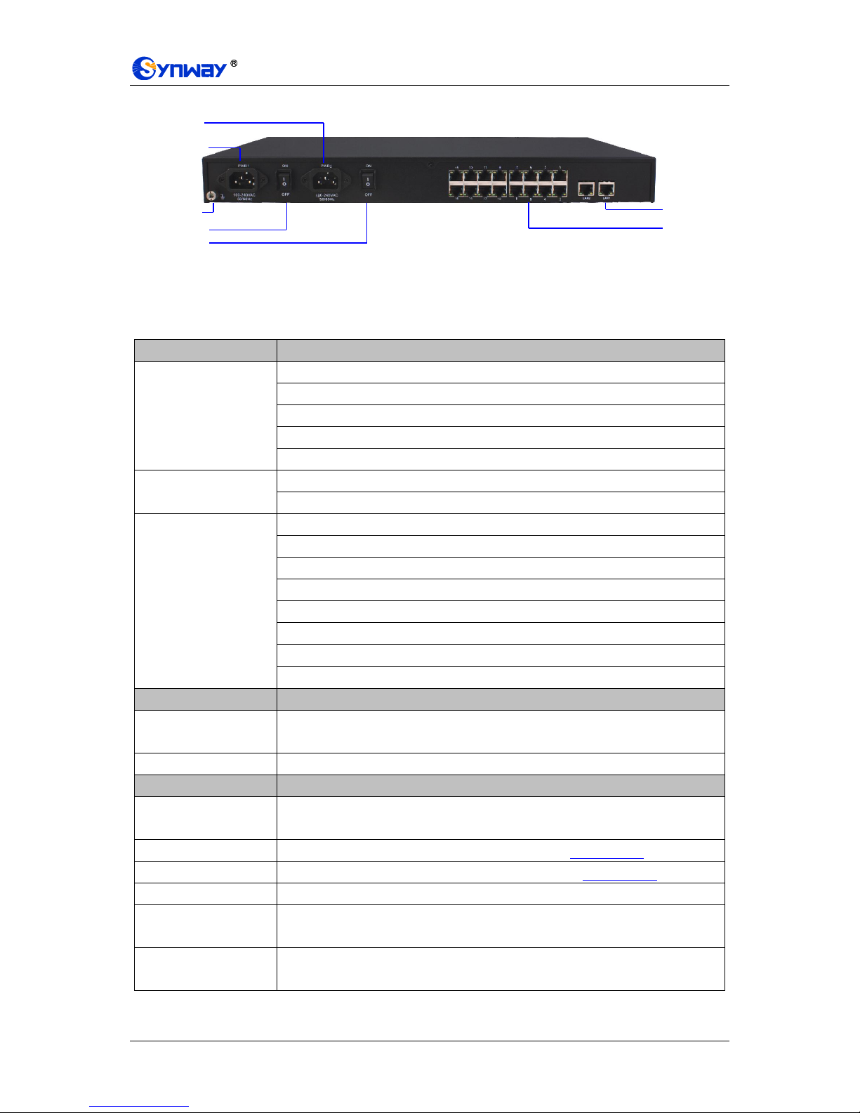
1.3 Hardware Description
The SMG digital gateway features 1U rackmount design and integrates embedded LINUX system
within the POWERPC+DSP hardware architecture. It has 1/2/4/8/16 E1/T1 ports and 2
Kilomega-Ethernet ports (LAN1 and LAN2) on the chassis.
(a) See below figures for SMG20000 series appearance:
Figure 1-2 Front View
Figure 1-3 Rear View
Figure 1-4 Left View
(b) See below figures for SMG3000 series appearance:
Figure 1-5 Front View
Ventilation
Holes
Screw Holes for
Foot Bracket
Power1 Key
220V AC
Power1
220V AC
Power2
Power2 Key
E1/T1
Interface
LAN
Grounding
Stud
LAN1 Indicator
Alarm Indicator
Power 1 Indicator
LAN2 Indicator
Console Port
Run Indicator
PCM Indicator
Power 2 Indicator
Reset Button
LAN1 Indicator
Alarm Indicator
Power 1 Indicator
LAN2 Indicator
Console Port
Run Indicator
PCM Indicator
Power 2 Indicator
Reset Button
Synway Information Engineering Co., Ltd
SMG Series Digital Gateway User Manual (Version 1.6.0) Page 4
Figure 1-6 Rear View
Note: The left view for SMG3000 series is same as that for SMG2000 series, refer to Figure 1-4.
The table below gives a detailed introduction to the interfaces, buttons and LEDs illustrated
above:
Interface
Description
LAN
Amount: 2
Type: RJ-45
Bandwidth: 10/100/1000Mbps
Self-Adaptive Bandwidth Supported
Auto MDI/MDIX Supported
E1/T1
Amount: 1/2/4/8/16
Type: RJ-45
Console Port
Amount: 1
Type: RS-232
Baud Rate: 115200 bps
Connector: RJ45 (See Figure 1-7 for signal definition)
Data Bits: 8 bits
Stop Bit: 1 bit
Parity Unsupported
Flow Control Unsupported
Button
Description
Power Key
Power on/off the SMG digital gateway. You can turn on the two power keys at the
same time to have the power supply working in the hot-backup mode.
Reset Button
Restore the gateway to factory settings.
LED
Description
Power Indicator
Indicates the power state. It lights up when the gateway starts up with the power
cord well connected.
Run Indicator
Indicates the running status. For more details, refer to 1.4 Alarm Info.
Alarm Indicator
Alarms the device malfunction. For more details, refer to 1.4 Alarm Info.
Link Indicator
The green LED on the left of LAN, indicating the network connection status.
ACT Indicator
The orange LED on the right of LAN, whose flashing tells data are being
transmitted.
E1/T1 Indicators
The green LED on the right of E1/T1 interface lights up and keeps on after the
E1/T1 module is successfully synchronized.
Power1 Key
220V AC
Power1
220V AC
Power2
Power2 Key
E1/T1
Interface
LAN
Grounding
Stud
Synway Information Engineering Co., Ltd
SMG Series Digital Gateway User Manual (Version 1.6.0) Page 5
Channel Indicators
Indicates the synchronization status of E1/T1 channels. It will light up and keep on
if E1/T1 is synchronized; otherwise, it will go out.
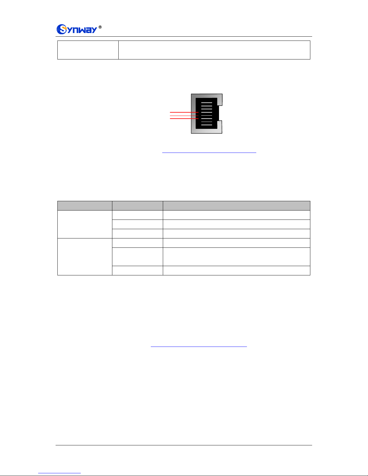
Note: The console port is used for debugging. While connection, the transmitting and receiving
lines of the gateway and the remote device should be cross-linked. That is, connect the
transmitting line of the gateway to the receiving line of the remote device, and vice verse. The
figure below illustrates the signal definition of the console port on the gateway.
Figure 1-7 Console Port Signal Definition
For other hardware parameters, refer to Appendix A Technical Specifications.
1.4 Alarm Info
The SMG digital gateway is equipped with two indicators denoting the system‟s running status:
Run Indicator (green) and Alarm Indicator (red). The table below explains the states and
meanings of the two indicators.
LED
State
Description
Run Indicator
Go out
System is not yet started.
Light up
System is starting.
Flash
Device is running normally.
Alarm Indicator
Go out
Device is working normally.
Light up
Upon startup: Device is running normally.
In runtime: Device goes abnormal.
Flash
System is abnormal.
Note:
The startup process consists of two stages: System Booting and Gateway Service
Startup. The system booting costs about 1 minute and once it succeeds, both the run
indicator and the alarm indicator light up. Then after the gateway service is successfully
started and the device begins to work normally, the run indicator flashes and the alarm
indicator goes out.
During runtime, if the alarm indicator lights up or flashes, it indicates that the device goes
abnormal. If you cannot figure out and solve the problem by yourself, please contact our
technicians for help. Go to Appendix E Technical/sales Support to find the contact way.
8
7
6
5
4
3
2
1
GND
Gateway TX
Gateway RX

Synway Information Engineering Co., Ltd
SMG Series Digital Gateway User Manual (Version 1.6.0) Page 6
Chapter 2 Quick Guide
This chapter is intended to help you grasp the basic operations of the SMG digital gateway in the
shortest time.
Step 1: Confirm that your packing box contains all the following things.
SMG Series Digital Gateway *1
Angle Bracket *2, Rubber Foot Pad *4, Screw for Angle Bracket *8
220V Power Cord *2
Warranty Card *1
Installation Manual *1
Step 2: Properly fix the SMG digital gateway.
If you do not need to place the gateway on the rack, simply fix the 4 rubber foot pads. Otherwise,
you should first fix the 2 angle brackets onto the chassis and then place the chassis on the rack.
Step 3: Connect the power cord.
Make sure the device is well grounded before you connect the power cord. Check if the power
socket has the ground wire. If it doesn‟t, use the grounding stud on the rear panel of the device
(See Figure 1-3) for earthing.
Note: Each SMG digital gateway has two power interfaces to meet the requirement for power
supply hot backup. As long as you properly connect and turn on these two power keys, either
power supply can guarantee the normal operation of the gateway even if the other fails.
Step 4: Connect the network cable.
Step 5: Connect the E1/T1 trunk. Connect the E1/T1 interface of the digital gateway to that
of the remote device by E1/T1 trunk. After connection, check if the synchronization
indicator (green LED) is lit and keeps on, which indicates that the E1/T1 trunk is well
connected and the E1/T1 module is successfully synchronized.
For the 75Ω-unbalanced coaxial cable, in consideration of various line conditions, each PCM on
the digital gateway is equipped with two grounding jumpers which respectively control the
grounding of the transmitting and the receiving end. Under normal condition, that is, the chassis of
the gateway is well grounded, the grounding jumpers at the receiving end should be disconnected
and the ones at the transmitting end should be short-circuited. This configuration is the factory
default setting and applicable in most situations so that there is usually no need to change it. For
the 120Ω-balanced twisted pair cable, the grounding jumpers at both ends should be
disconnected.
You can construct an E1 trunk according to Figure 2-1. Prevent reverse connection of the
transmitting and receiving lines. The state of the receiving line can be checked by the
synchronization indicator (green LED) of the E1 interface. When the receiving line is in a normal
state, the indicator is lit and keeps on. If the indicator is off or flashing, it means that the
connection of the receiving line may probably be reversed. However, the state of the transmitting
line can only be examined by the opposite terminal. The synchronization indicator starts working
only after the device is powered on and successfully initialized.
8
7
6
5
4
3
2
1
RTip
RRing
Receive
TTip
TRing
Transmit

Synway Information Engineering Co., Ltd
SMG Series Digital Gateway User Manual (Version 1.6.0) Page 7
Figure 2-1 Pin Layout for E1 Interface
Step 6: Log in the gateway.
Enter the original IP address (LAN 1: 192.168.1.101 or LAN 2: 192.168.0.101) of the SMG digital
gateway in the browser to go to the WEB interface. The original username and password of the
gateway are both „admin‟. For detailed instructions about login, refer to 3.1 System Login. We
suggest you change the initial username and password via „System Tools Change Password‟
on the WEB interface as soon as possible after your first login. For detailed instructions about
changing the password, refer to 3.12.15 Change Password. After changing the password, you are
required to log in again.
Step 7: Modify IP address of the gateway.
You can modify the IP address of the gateway via „System Tools Network‟ on the WEB interface
to put it within your company‟s LAN. Refer to 3.12.1 Network for detailed instructions about IP
modification. After changing the IP address, you shall log in the gateway again using your new IP
address.
Step8: Set PCM.
On your initial use of the SMG digital gateway, you shall enter the PCM interface and set the
configuration items „Signaling Protocol‟ and „Interface‟. These items must be in conformity with the
physical connection. You may use the default values of other configuration items. Refer to 3.4.3
PCM for detailed instructions about PCM Settings.
Note: You shall restart the service to validate the settings in this step. Refer to 3.12.17 Restart for
detailed instructions.
Step 9: Configure signaling protocol parameters.
Further configure the signaling protocol you set in Step 8. Different protocols are configured on
different interfaces. See below for detailed instructions.
SS7-ISUP:
Note: For your easy understanding and manipulation, this step does not involve the ISUP
quasi-associated mode configuration and the dual gateway feature. For descriptions about
these configurations, refer to 3.5 SS7 Settings.
The configuration interfaces related to SS7-ISUP include: SS7, ISUP and SS7 Server.
On your initial use of the SMG digital gateway, you may adopt the default values of the
configuration items on the SS7 and ISUP interfaces. Note that the SS7 Server interface must be
configured properly. Otherwise, the PSTN trunks may be unavailable. Follow the instructions here
to configure the SS7 Server:
Step 1: Set OPC, Server IP and Signaling Point Code Standard. The OPC is generally allocated
by the central office. The Server IP is the IP address of the SS7 server and you may use
its default value. The Signaling Point Code Standard, which varies on the PBX model,
can be set to 24 or 14. After modification, click the ‘Modify’ button on the right to save
the settings.
Step 2: Modify the current link or click the „Add New‟ button below the signaling link list to add a
new link. Enter the physical address of the actually used signaling PCM (E1 interface)
and click „Save‟ to save the modification. If only one PCM is used for signaling in the
gateway, you need just configure one signaling link.
Step 3: Modify the current linkset or click the „Add New‟ button below the signaling linkset list to
add a new linkset. You shall select the link configured in Step 2 for „Link‟ and use the
default values for the other configuration items. After modification, click ‘Save’.
Step 4: Modify the current DPC or click the „Add New‟ button below the DPC list to add a new
DPC. Fill in „SP Code‟ with the signaling point code of the remote end (i.e. signaling
destination), select the linkset configured in Step 3 for „Linkset‟ and use the default
values for the other configuration items. After modification, click ‘Save’.

Synway Information Engineering Co., Ltd
SMG Series Digital Gateway User Manual (Version 1.6.0) Page 8
Step 5: Modify the current CIC routing rule or click the „Add New‟ button below the ISUP_CIC
routing rule list to add a new CIC routing rule. Select the DPC configured in Step 4 for
„DPC‟, fill in „CIC_PCM‟ according to the actual allocation and use the default values for
the other configuration items. After modification, click ‘Save’. Note that if multiple PCMs
in the gateway are used for voice transmission, they should be configured with multiple
CIC routing rules accordingly.
Note: After configuring SS7-ISUP related interfaces, you shall restart the service to validate the
settings. Refer to 3.12.17 Restart for detailed instructions.
SS7-TUP:
Note: For your easy understanding and manipulation, this step does not involve the TUP
quasi-associated mode configuration and the dual gateway feature. For descriptions about
these configurations, refer to 3.5 SS7 Settings.
The configuration interfaces related to SS7-TUP include: SS7, TUP and SS7 Server.
On your initial use of the SMG digital gateway, you may adopt the default value of the
configuration items on the SS7 and TUP interfaces. Note that the SS7 Server interface must be
configured properly. Otherwise, the PSTN trunks may be unavailable. Follow the instructions here
to configure the SS7 Server:
Step 1: Set OPC, Server IP and Signaling Point Code Standard. The OPC is generally allocated
by the central office. The Server IP is the IP address of the SS7 server and you may use
its default value. The Signaling Point Code Standard, which varies on the PBX model,
can be set to 24 or 14. After modification, click the ‘Modify’ button on the right to save
the settings.
Step 2: Modify the current link or click the „Add New‟ button below the signaling link list to add a
new link. Enter the physical address of the actually used signaling PCM (E1 interface)
and click „Save‟ to save the modification. If only one PCM is used for signaling in the
gateway, you need just configure one signaling link.
Step 3: Modify the current linkset or click the „Add New‟ button below the signaling linkset list to
add a new linkset. You shall select the link configured in Step 2 for „Link‟ and use the
default values for the other configuration items. After modification, click ‘Save’.
Step 4: Modify the current DPC or click the „Add New‟ button below the DPC list to add a new
DPC. Fill in „SP Code‟ with the signaling point code of the remote end (i.e. signaling
destination), select the linkset configured in Step 3 for „Linkset‟ and use the default
values for the other configuration items. After modification, click ‘Save’.
Step 5: Modify the current CIC routing rule or click the „Add New‟ button below the TUP_CIC
routing rule list to add a new CIC routing rule. Select the DPC configured in Step 4 for
„DPC‟, fill in „CIC_PCM‟ according to the actual allocation and use the default values for
the other configuration items. After modification, click ‘Save’. Note that if multiple PCMs
in the gateway are used for voice transmission, they should be configured with multiple
CIC routing rules accordingly.
Note: After configuring SS7-TUP related interfaces, you shall restart the service to validate the
settings. Refer to 3.12.17 Restart for detailed instructions.
ISDN User Side/Network Side:
The configuration interface related to ISDN User Side/Network Side is ISDN. On your initial use of
the SMG digital gateway, you may adopt the default value of the configuration items on this
interface.
Note: After configuring the ISDN interface, you shall restart the service to validate the settings.
Refer to 3.12.17 Restart for detailed instructions.
SS1:
The configuration interface related to SS1 is SS1. On your initial use of the SMG digital gateway,

Synway Information Engineering Co., Ltd
SMG Series Digital Gateway User Manual (Version 1.6.0) Page 9
you may adopt the default value of the configuration items on this interface.
Note: After configuring the SS1 interface, you shall restart the service to validate the settings.
Refer to 3.12.17 Restart for detailed instructions.
Step 10: Check the PSTN status.
After the configuration of signaling protocols, you can check the status of the PSTN trunks via
„Operation Info PSTN Status‟. Refer to 3.2.2 PSTN Status for detailed introductions. When
Time Slot 0 shows „Frame Synchronized‟, the signaling time slot is in the state of „Signaling
Channel‟ and all the other channels are „Idle‟, it indicates the PCM is well configured. If Time Slot
0 or the signaling time slot shows „Faulty‟ or the other channels are in the state of „Unavailable‟,
there may be errors in the signaling protocol configurations and we suggest you return to Step 9
for check.
Step 11: Set routing rules for calls.
Note: For your easy understanding and manipulation, all examples given in this step do not
involve registration.
Situation 1: IP PSTN
Step 1: Configure the IP address of the remote SIP terminal which can establish conversations
with the gateway so that the calls from other terminals will be ignored. Refer to „VOIP
Settings SIP Trunk‟ for detailed instructions. Fill in „Remote IP‟ and „Remote Port‟ with
the IP address and port of the remote SIP terminal which will initiate calls to the gateway.
You may use the default values for the other configuration items.
Example: Provided the IP address of the remote SIP terminal is 192.168.0.111 and the
port is 5060. Add SIP Trunk 0; set Remote IP to 192.168.0.111 and Remote Port to
5060.
Step 2: Add the IP address of the remote SIP terminal configured in Step 1 into the
corresponding SIP trunk group. Refer to „VoIP Settings SIP Trunk Group‟ for detailed
instructions. Select the SIP trunk configured in Step 1 as „SIP Trunks‟. You may use the
default values for the other configuration items.
Example: Add SIP Trunk Group 0. Check the checkbox before 0 for SIP Trunks and
keep the default values for the other configuration items.
Step 3: Add PCM into the corresponding PCM Group. Refer to „PCM Settings PCM Trunk
Group‟ for detailed instructions. Select the PCM used for call conversation as „PCM‟. You
may use the default values for the other configuration items.
Example: Provided the PCM used for call conversation is PCM[1]. Add PCM Trunk
Group 0, check the checkbox before PCM[1] and keep the default values for the other
configuration items.
Step 4: Add routing rules. Refer to „Route Settings IPPSTN‟ for detailed instructions. Select
the SIP trunk group set in Step 2 as „Call Initiator‟ and the PCM trunk group set in Step 3
as „Call Destination‟. You may use the default values for the other configuration items.
Example: Select SIP Trunk Group[0] as Call Initiator and PCM Trunk Group[0] as
Call Destination. Keep the default values for the other configuration items.
Step 5: Initiate a call from the SIP terminal configured in Step 1 to the IP address and port of the
SMG digital gateway. Thus you can establish a call conversation via PCM[1] with the
PSTN terminal. (Note: The format used for calling an IP address via SIP trunk is as
follows: username@IP address, in which, „username‟ is a called party number which
conforms to the number-receiving rule of the remote device.)
Example: Provided the IP address of the SMG digital gateway is 192.168.0.101 and the
port is 5060. Provided 123 is a number which conforms to the number receiving rule of
the remote device. Initiate a call from SIP terminal 0 to the IP address 192.168.0.101 (in
the format: 123@192.168.0.101) and you can establish a call conversation via PCM[1] to

Synway Information Engineering Co., Ltd
SMG Series Digital Gateway User Manual (Version 1.6.0) Page 10
the number 123.
Situation 2: PSTN IP
Step 1: Configure the called party numbers which are received from PSTN and will be processed
by the gateway. Refer to „Advanced Settings Number-receiving Rule‟ for detailed
instructions. Enter either a particular number or a string of „x‟s to represent several
random numbers. For example, „xxx‟ denotes 3 random numbers. You may use the
default value for „Index‟.
Example: Set Index to 99 and configure Dial Rule to 123.
Step 2: Set the IP address of the SIP terminal to be called by the gateway. Refer to „VOIP
Settings SIP Trunk‟ for detailed instructions. Fill in „Remote IP‟ and „Remote Port‟ with
the IP address and port of the SIP trunk. You may use the default values for the other
configuration items.
Example: Provided the IP address of the SIP trunk to be called is 192.168.0.111 and the
port is 5060. Add SIP Trunk 0; set Remote IP to 192.168.0.111 and Remote Port to
5060.
Step 3: Add the IP address of the remote SIP terminal configured in Step 2 into the
corresponding SIP trunk group. Refer to „VoIP Settings SIP Trunk Group‟ for detailed
instructions. Select the SIP trunk configured in Step 2 as „SIP Trunks‟. You may use the
default values for the other configuration items.
Example: Add SIP Trunk Group 0. Check the checkbox before 0 for SIP Trunks and
keep the default values for the other configuration items.
Step 4: Add PCM into the corresponding PCM Group. Refer to „PCM Settings PCM Trunk
Group‟ for detailed instructions. Select the PCM used for call conversation as „PCM‟. You
may use the default values for the other configuration items.
Example: Provided the PCM used for call conversation is PCM[1]. Add PCM Trunk
Group 0, check the checkbox before PCM[1] and keep the default values for the other
configuration items.
Step 5: Add routing rules. Refer to „Route Settings PSTNIP‟ for detailed instructions. Select
the PCM trunk group set in Step 4 as „Call Initiator‟ and the SIP trunk group set in Step 3
as „Call Destination‟. You may use the default values for the other configuration items.
Example: Select PCM Trunk Group[0] as Call Initiator and SIP Trunk Group[0] as
Call Destination. Keep the default values for the other configuration items.
Step 6: Once PCM[1] receives a call from PSTN and the called party number conforms to the
number-receiving rules set in Step 1, it can establish a call conversation with the remote
SIP terminal via the gateway.
Example: Once PCM[1] receives a call from PSTN with the called party number 123, it
will route the call to SIP Trunk 0 of the gateway.
Special Instructions:
The chassis of the SMG digital gateway must be grounded for safety reasons, according
to standard industry requirements. A simple way is earthing with the third pin on the plug
or the grounding studs on the machine. No or improper grounding may cause instability
in operation as well as decrease in lightning resistance.
As the device will gradually heat up while being used, please maintain good ventilation to
prevent sudden failure, ensuring that the ventilation holes (see Figure 1-4) are never
jammed.
During runtime, if the alarm indicator lights up or flashes, it indicates that the device goes
abnormal. If you cannot figure out and solve the problem by yourself, please contact our

Synway Information Engineering Co., Ltd
SMG Series Digital Gateway User Manual (Version 1.6.0) Page 11
technicians for help. Otherwise it may lead to a drop in performance or unexpected
errors.

Synway Information Engineering Co., Ltd
SMG Series Digital Gateway User Manual (Version 1.6.0) Page 12
Chapter 3 WEB Configuration
3.1 System Login
Type the IP address into the browser and enter the login interface. See Figure 3-1.
Figure 3-1 Login Interface
The gateway only serves one user, whose original username and password are both „admin‟. You
can change the username and the password via „System Tools Change Password‟ on the WEB
interface. For detailed instructions, refer to 3.12.15 Change Password.
After login, you can see the main interface as below.
Figure 3-2 Main Interface

Synway Information Engineering Co., Ltd
SMG Series Digital Gateway User Manual (Version 1.6.0) Page 13
3.2 Operation Info
Operation Info includes four parts: System Info, PSTN Status, SS7 Server and Call Count,
showing the current running status of the gateway. See Figure 3-3.
Figure 3-3 Operation Info
3.2.1 System Info
Figure 3-4 System Info Interface
See Figure 3-4 for the system info interface. You can click Refresh to obtain the latest system

Synway Information Engineering Co., Ltd
SMG Series Digital Gateway User Manual (Version 1.6.0) Page 14
information. The table below explains the items shown in Figure 3-4.
Item
Description
MAC Address
MAC address of LAN 1 or LAN 2.
IP Address
The three parameters from left to right are IP address, subnet mask and default
gateway of LAN 1 or LAN 2.
DNS Server
DNS server address of LAN 1 or LAN 2.
Receive Packets
The amount of receive packets after the gateway‟s startup, including three
categories: All, Error and Drop.
Transmit Packets
The amount of transmit packets after the gateway‟s startup, including three
categories: All, Error and Drop.
Current Speed
The current speed of data receiving and transmitting.
Work Mode
The work mode of the network, including five options: 10 Mbps Half Duplex, 10
Mbps Full Duplex, 100 Mbps Half Duplex, 100 Mbps Full Duplex and 1000 Mbps
Full Duplex.
Runtime
Time of the gateway keeping running normally after startup. This parameter
updates every 2s.
Operating Mode
The operating mode of the gateway includes:
Operating Mode
Description
Master Server
The current gateway applies the SS7 protocol and is
used for both signaling and voice transmission. If the
dual gateway feature is enabled, the current gateway
serves as the master server.
Slave Server
The current gateway applies the SS7 protocol and is
used for both signaling and voice transmission. This
operating mode works only when the dual gateway
feature is enabled and the current gateway serves as the
slave server.
Client
The current gateway applies the SS7 protocol and is
only used for voice transmission.
ISDN(User-side)
The current gateway is configured to be ISDN user-side..
ISDN(Network-side)
The current gateway is configured to be ISDN
network-side.
SS1
The current gateway is configured to be SS1.
Serial Number
Unique serial number of an SMG digital gateway.
WEB
Current version of the WEB interface.
Gateway
Current version of the gateway service.
Uboot
Current version of Uboot.
Kernel
Current version of the system kernel on the gateway.
Firmware
Current version of the firmware on the gateway.

Synway Information Engineering Co., Ltd
SMG Series Digital Gateway User Manual (Version 1.6.0) Page 15
3.2.2 PSTN Status
Figure 3-5 PSTN Status Interface for E1 Lines
Figure 3-6 PSTN Status Interface for T1 Lines
See Figure 3-5 and Figure 3-6 for the PSTN status interface which shows the real-time status of
each PCM on the gateway, including line synchronization, signaling link information and channel
states.
Item
Description
Port
Serial number of the E1/T1 port on the device.
Time Slot No.
PCM time slot number in the port.
State
Displays the channel state in real time. You can move the mouse onto the channel
state icon for detailed information about the channel and the call, such as: call
direction, calling party number and called party number.
For Time Slot 0, the channel state indicates the synchronization status of
E1/T1.
State
Color
Description

Synway Information Engineering Co., Ltd
SMG Series Digital Gateway User Manual (Version 1.6.0) Page 16
Frame Sync
Frame synchronization normal. The synchronization
status is 0x0.
Faulty
Configuration errors or hardware failure.
You can move the mouse onto the icon for the
hexadecimal value for synchronization status which
consists of 16 bits and bit 0 is the lowest valid bit. If the
bit value is equal to 0, it indicates that the
synchronization status is normal; if the bit value is
equal to 1, see below for details:
bit0=1: basic frame synchronization loss
bit1=1: duration of the basic frame synchronization
loss exceeds 100ms
bit2=1: CAS re-synchronization
bit3=1: CRC re-synchronization
bit4=1: remote alarm indication
bit5=1: signal alarm indication
bit6=1: all-ones alarm signal of time slot 16
bit7=1: signal loss
bit9=1: MF alarm from the remote end
bit10=1: open circuit
bit11=1: short circuit
Other bits: reserved, all remain 0
For the signaling time slot, the channel states include:
State
Color
Description
Signaling
For SS7, this state indicates „SS7 in service‟.
For ISDN, this state indicates „multiple frames
established‟ or „timer recovery‟.
For SS1, this state indicates „time slot synchronization
normal‟.
Faulty
Configuration errors or hardware failure.
For SS7, this state indicates „SS7 out of service‟, „initial
alignment‟, „aligned ready‟, „aligned not ready‟ or
„processor outage‟.
For ISDN, this state indicates „TEI unassigned‟, „assign
awaiting TEI‟, „establish awaiting TEI‟, „TEI assigned‟,
„awaiting establishment „or „awaiting release‟.
For SS1, this state indicates „time slot synchronization
abnormal‟.
Unused
This state indicates the signaling time slot on this
E1/T1 is not used.
For the other channels, the channel states include:
State
Icon
Description
Unusable
The channel is unavailable.

Synway Information Engineering Co., Ltd
SMG Series Digital Gateway User Manual (Version 1.6.0) Page 17
Circuit Reset
The circuit is being reset.
Idle The channel is available.
Local Block
The channel is blocked by the local application program
and cannot receive incoming calls.
Remote Block
The channel is blocked by the specific circuit/circuit
group blocking messages sent from the remote PBX
and cannot make outgoing calls.
Both Block
The channel is blocked by the local end so as not to
receive incoming calls, meanwhile, it is blocked by the
remote PBX so as not to make outgoing calls either.
Wait Answer
The channel receives the ringback tone and is waiting
for the called party to pick up the phone.
Ringing
The channel is in the ringing state.
Talking
The channel is in a conversation.
Pending
The channel is in the pending state
Dialing
The channel is dialing.
Wait Message
The channel is waiting for the message from remote
PBX.
Statistics
The total amount of the channels for the corresponding status.
Note: The gateway provides the fuzzy search feature on this interface. After you click any
characters on Figure 3-5, Figure 3-6, and press the „F‟ button, the search box will emerge on the
right top of this page. Then you can input the key characters and the gateway will locate the
channel on which there is an ongoing call that conforms to the fuzzy search condition.
Take an example: As shown in Figure 3-7, after we input the character 888 to the search box, and
click the Search button, the gateway does a fuzzy search and locates that the ongoing call whose
CallerID contains the character 888 occurs on Channel 9.
Figure 3-7 Search Calls
Note: Click Record to start recording on the matched channel. If more than one channels match a
condition, only the channel with the largest number among them will be recorded.

Synway Information Engineering Co., Ltd
SMG Series Digital Gateway User Manual (Version 1.6.0) Page 18
3.2.3 SS7 Server
Users can see the SS7 Server option in the menu only when the configuration item Signaling
Protocol on the PCM settings interface is set to SS7-TUP or SS7-ISUP.
Figure 3-8 SS7 Server Info Interface
See Figure 3-8 for the SS7 server info interface. This interface contains 7 status bars (Status Bar
1~7 in the above figure) and a configuration region (Region 8 in the above figure). Below are the
detailed introductions.
Status Bar 1 & 2: Receive/transmit message list
The receive/transmit message lists display the received and sent messages respectively, used for
gateway debugging. The display content in these lists can be set by the configuration items in
Region 8.
Configuration Region 8: Properties configuration for receive/transmit message list
The table below explains the items in Configuration Region 8.
Item
Description
Server IP
IP address of the SS7 server, this item can be configured on the SS7 interface.
Work Mode
Work mode of the SS7 server which includes three modes: Master Server, Slave
Server and Client.
Display Sent
Messages
If this item is ticked, the transmit message list will display the message sent to the
remote end.
Display Received
Messages
If this item is ticked, the receive message list will display the message received from
the remote end.
Display DPC & OPC
If this item is ticked, the receive/transmit message list will display DPC and OPC.
Display SNT
Messages
If this item is ticked, the receive/transmit message list will display the SNT
messages.
Display SNM
Messages
If this item is ticked, the receive/transmit message list will display the SNM
messages.

Synway Information Engineering Co., Ltd
SMG Series Digital Gateway User Manual (Version 1.6.0) Page 19
Auto Translate
If this item is ticked, the received/sent messages displayed on this interface will be
translated automatically in the following format:
Date Time Total number Signaling link number# SIO Content
For the TUP messages, SIO is just „TUP‟ (0x84), followed by the message content.
It is usually in the following format:
Title code CIC=PCM:TS Message body
If this item is not ticked, the received/sent messages displayed on this interface will
be hexadecimal raw data.
Users can configure the display content of the receive/transmit message list via the checkbox
before each configuration item. After modification, click Save to apply the configurations. The
changes will be shown in the list in real time. Click Download and you can download the log
information of the SS7 server.
Status Bar 3: Linkset/signaling link information
This region displays the information about signaling links and linksets. The table below explains
the information items in Status Bar 3.
Item
Description
Linkset No.
Linkset number.
Linkset Status
Working state of the linkset, including In service and Out of service. A signaling
linkset will go into the state In service as long as one link in it is at the state of In
service.
Link@Physical
Address
Signaling link number and its physical position. For example, „0 @ IP[0]:PCM[0]‟
means the physical position of Link 0 in this gateway is the E1 with the local PCM
numbered 0 on Client 0.
Network
Whether the signaling link is registered to the gateway, including two states:
Connected and Disconnected (or no display). The signaling link can be used
normally only in the state of Connected.
Sync
Basic frame synchronization (Time Slot 0), including two states: Sync and Async.
The signaling link can be used only in the state of Sync.
Link Status
Working state of the signaling link, including In service and Initial alignment. You
can refer to „Status Bar 6: Link information‟ for detailed information about link status.
Hold Time
Duration since the last time the signaling link enters into the state of In service.
Position
Times of positioning that occurs on the signaling link since the program starts.
Send MSU
Total number of messages sent on the signaling link since the program starts.
Receive MSU
Total number of messages received on the signaling link after the program starts.
Switchover MSU
Total number of messages switched over on the signaling link since the program
starts.
Status Bar 4: Client information
This region displays the information about client IP address and connection state. The table below
explains the information items in Status Bar 4.
Item
Description
Client
Client number.
Synway Information Engineering Co., Ltd
SMG Series Digital Gateway User Manual (Version 1.6.0) Page 20
IP Address
IP address of the client. You can click the link of the IP address to visit the WEB
interface of the client.
Network
Whether the client has been successfully connected to the gateway, including two
states: Connected and Disconnected (or no display).
Status Bar 5: DPC Information
This region displays the information about DPC. The table below explains the information items in
Status Bar 5.
Item
Description
DPC#
DPC number which starts from 0.
DPC Code
Destination point code which is usually allocated by the central office.
DPC Status
Indicates whether the route to this DPC is available, involving two states Available
and Unavailable. The message can be sent to the DPC only when the route to this
DPC is at the state of Available. The DPC will turn into the state of Available as long
as one of the linksets reaching the DPC is at the state of In Service.
DPC Route Table
Route to the DPC, i.e. linkset number.
Status Bar 6: Link information
This status bar displays the detailed information on the state of all signaling links, usually used for
searching the cause of service interrupt on a signaling link.
Link#
STA
L2
POC
LSC
FSN
ERR
CHO
Link
Number
Link States
0-6
Link Failure
Causes
(interrupt)
Processor
Failures
0-3
Live
Communication
Server Service
0-1
Forward
Sequence
Number
spare
spare
0: uploaded
but not
started
0: normal
0: normal
0: service is
unavailable
1: service
interrupt
1: BSNR illegal
1: the
local end
processor
failure
1: service is
available
2: initial
positioning
2: FIBR illegal
2: the
remote
end
processor
failure
3:
positioned/
ready
3: T2 timeout
3: both
ends
processor
failure
4:
positioned/
not ready
4: T6 timeout, the
remote end busy

Synway Information Engineering Co., Ltd
SMG Series Digital Gateway User Manual (Version 1.6.0) Page 21
5: service
on
5: L3 sends a
command to stop
6:
processor
failure
6: signaling
error rate too high
7: during the
course of initial
positioning, fail to
enter a normal
position
8: Timer 1
timeout
9: positioned and
ready, receive the
interrupt signal of
the remote end
10: positioned but
not ready,
receive the
interrupt signal of
the remote end
11: in the state of
Service On,
receive the
interrupt signal of
the remote end
12: in a processor
failure, receive
the interrupt
signal of the
remote end
Status Bar 7: Runtime Log
Runtime log records all MTP3 commands and error information that pops up during the operation.
This status bar displays all the log records generated after the digital gateway starts.

Synway Information Engineering Co., Ltd
SMG Series Digital Gateway User Manual (Version 1.6.0) Page 22
3.2.4 Call Count
Figure 3-9 Call Count Interface
See Figure 3-9 for the call count Interface. The above list shows the detailed information about all
the calls counted from the startup of the gateway service to the latest open or refresh of this
interface. This interface includes three parts: PSTN Call Statistics, Statistics on PSTN Release
Cause and Statistics on Sip Release Cause. You can click Refresh to obtain the latest call count
information. The table below explains the items shown in Figure 3-9.
Item
Description
Trunk No.
The number of the PCM trunk, numbered from 0.
Signaling Type
The signaling protocol applied on the digital trunk, including: ISDN User Side, ISDN
Network Side, SS7-TUP, SS7-ISUP, and SS1.
Current Number of
IP PSTN
The number of current calls from IP to PSTN.
Total Number of IP
PSTN
The total number of current calls from IP to PSTN.
Connection Rate of
IP PSTN
The percentage of successful IP PSTN calls to total IP PSTN calls.
Current Number of
PSTN IP
The number of current calls from PSTN to IP.
Total Number of
PSTN IP
The total number of current calls from PSTN to IP.
Connection Rate of
PSTN IP
The percentage of successful PSTN IP calls to total PSTN IP calls.
Total
Total number and connection rate of calls on all available tunks
Release Cause
Reason to release the call.
Normal call clearing
Total number of the calls which are normally cleared.
Synway Information Engineering Co., Ltd
SMG Series Digital Gateway User Manual (Version 1.6.0) Page 23
Cancelled by calling
party
Total number of the calls which are cancelled by the calling party.
User busy
Total number of the calls which fail as the called party has been occupied and
replies a busy message.
No answer from
user
Total number of the calls which fail as the called party does not pick up the call in a
long time or the calling party hangs up the call before the called party picks it up.
Routing failed
Total number of the calls which fail because no routing rules are matched.
Resource
unavailable
Total number of the calls which fail because no voice channel is available.
Unallocated number
Total number of the calls which fail as the called party number is unallocated.
Call rejected
Total number of the calls which fail as the called party replies a rejection message.
Normal unspecified
Total number of the calls which fail as the called party number is normal but
unspecified.
Call failed
Total number of the calls which fail as the called party number does not conform to
the number-receiving rule or for relative reasons.
Others
Total number of the calls which fail due to other unknown reasons.
Percentage
The percentage of the calls with a release cause to total calls.
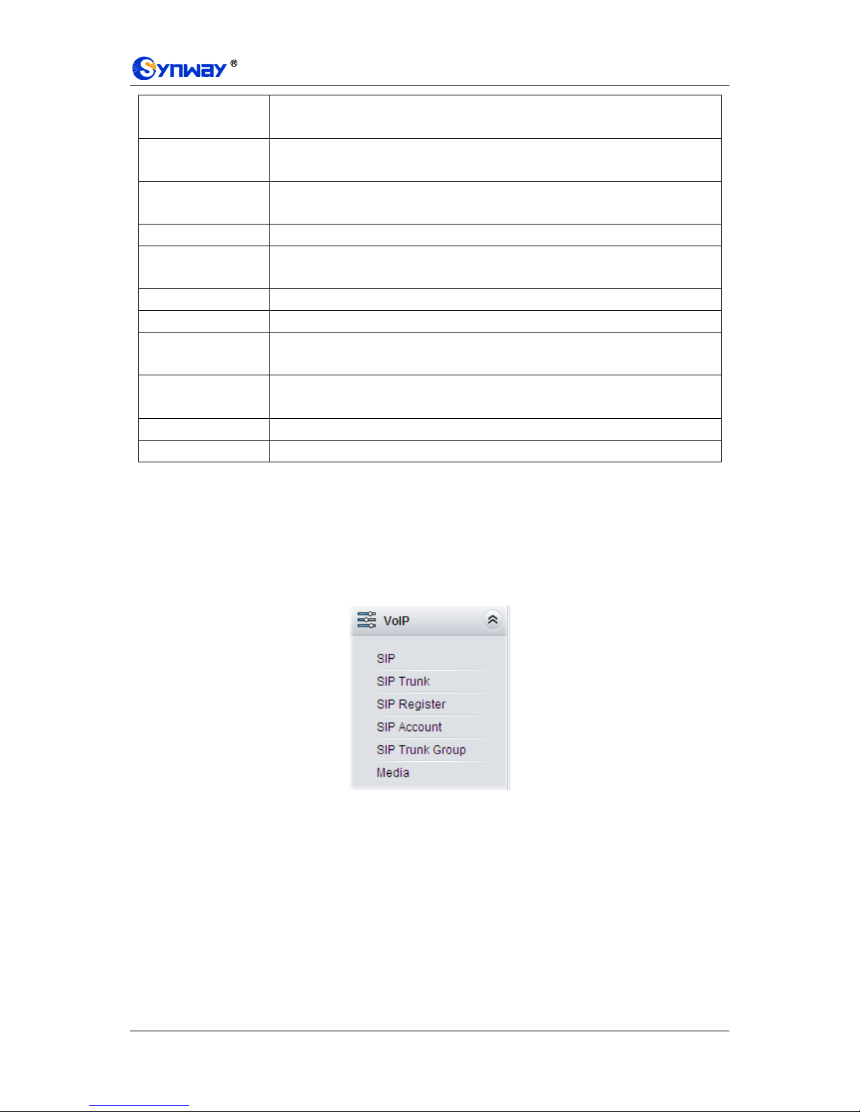
3.3 VoIP Settings
VoIP Settings includes five parts: SIP, SIP Trunk, SIP Register, SIP Account, SIP Trunk Group
and Media. See Figure 3-10. SIP is used to configure the general SIP parameters; SIP Trunk is
used to set the basic and register information of the SIP trunk; SIP Register is used for the
registration of SIP; SIP Account is used for registering SIP accounts to the SIP server; SIP Trunk
Group is to manage SIP trunks by group; and Media is to set the RTP port and the payload type.
Figure 3-10 VoIP Settings
Synway Information Engineering Co., Ltd
SMG Series Digital Gateway User Manual (Version 1.6.0) Page 24
3.3.1 SIP Settings

Synway Information Engineering Co., Ltd
SMG Series Digital Gateway User Manual (Version 1.6.0) Page 25
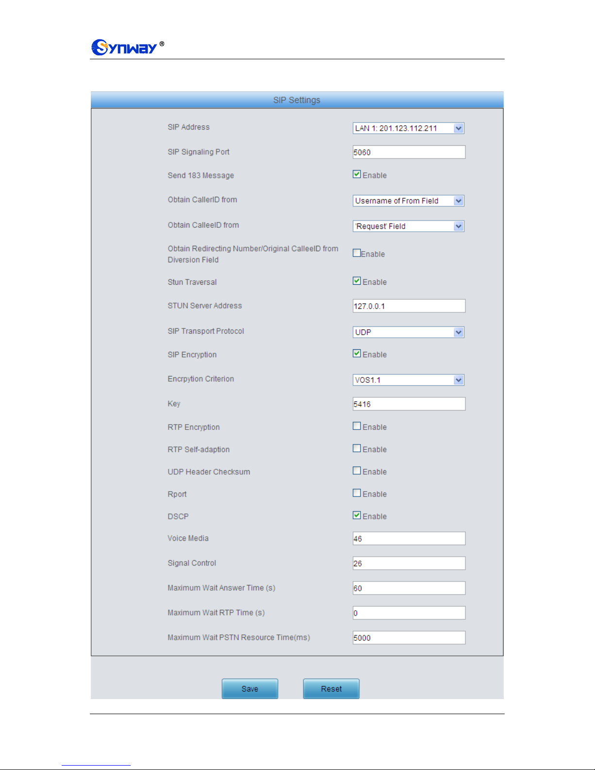
Figure 3-11 SIP Settings Interface
See Figure 3-11 for the SIP settings interface where you can configure the general SIP
parameters. After configuration, click Save to save your settings into the gateway or click Reset to
restore the configurations. If a dialog box pops up after you save your settings asking you to
restart the service, do it immediately to apply the changes. Refer to 3.12.17 Restart for detailed
instructions. The table below explains the items shown in Figure 3-11.
Item
Description
SIP Address
IP address for SIP signaling, using LAN 1 by default.
SIP Port
Monitoring port of SIP signaling. Range of value: 1024~65535, with the default
value of 5060.
183 Message
Behavior
Sets whether to send the 183 message instead of 180 to respond to the ringing tone
when the SIP end serves as the called party. By default this feature is enabled.
Obtain CallerID from
There are two optional ways to obtain the calling party number: from Username of
“From” Field or from Displayname of “From” Field. The default value is from
Username of “From” Field.
Obtain CalleeID
from
There are two optional ways to obtain the called party number: from “To” Field or
from “Request” Field. The default value is from “Request” Field.
Obtain Redirecting
Number/Original
CalleeID from
Diversion Field
Sets whether to enable the feature of obtaining the Redirecting Number/Original
CalleeID from Diversion Field. By default, the feature is disabled.
STUN Traversal
Sets whether to enable the STUN server for NAT traversal. By default the STUN
server is disabled.
STUN Server
Address
Address of the server for STUN traversal.
SIP Transport
Protocol
There are two modes UDP and TCP available for running the SIP protocol. The
default value is UDP.
SIP Encryption
Once this feature is enabled, you can encrypt the SIP signal following selecting an
encryption criterion and setting a key. By default it is disabled.
Encryption Criterion
The criterion used to encrypt the SIP signal. At present only VOS1.1 is supported.
Key
The key to encrypt the SIP signal.
RTP Encryption
Once this feature is enabled, you can encrypt the RTP package. By default it is
disabled.
RTP Self-adaption
When this feature is enabled, the RTP reception address or port carried by the
signaling message from the remote end, if not consistent with the actual state, will
be updated to the actual RTP reception address or port. By default, this feature is
disabled.
UDP Header
Checksum
When this feature is enabled, the gateway will automatically calculate the check
sum of the UDP header during RTP transmission.
Rport
When this feature is enabled, a corresponding Rport field will be added to the Via
message of SIP. By default, it is disabled.
DSCP
Sets whether to enable the DSCP differentiated services code point. By default, it is
disabled.

Synway Information Engineering Co., Ltd
SMG Series Digital Gateway User Manual (Version 1.6.0) Page 26
Voice Media
Sets the priority of the voice media for DSCP. The voice media with a bigger value
has a higher priority. The value range is 0~63, with the default value of 46.
Signal Control
Sets the priority of the signal control for DSCP. The signal control with a bigger
value has a higher priority. The value range is 0~63, with the default value of 26.
Maximum Wait
Answer Time
Sets the maximum time for the SIP channel to wait for the answer from the called
party of the outgoing call it initiates. If the call is not answered within the specified
time period, it will be canceled by the channel automatically. The default value is 60,
calculated by s.
Maximum Wait RTP
Time
Sets the maximum time for the SIP channel to wait for the RTP packet. If no RTP
packet is received within the specified time period, the channel will enter the
pending state automatically and release the call. The default value is 0, calculated
by s.
Maximum Wait
PSTN Resource
Time
Sets the maximum wait time to search the idle PSTN resource for the incoming call
from IP. The call will be failed if no channel is found during this time. The value
range is 0~10000, calculated by ms, with the default value of 5000.
3.3.2 SIP Trunk
Figure 3-12 SIP Trunk Settings Interface
See Figure 3-12 for the SIP trunk settings interface. A new SIP trunk can be added by the Add
New button on the bottom right corner of the list in the above figure. See Figure 3-13 for the SIP
trunk adding interface.
Figure 3-13 Add New SIP Trunk
The table below explains the items shown in Figure 3-13.

Synway Information Engineering Co., Ltd
SMG Series Digital Gateway User Manual (Version 1.6.0) Page 27
Item
Description
Index
The unique index of each SIP trunk.
Remote Address
Address of the SIP trunk, i.e. the IP address or domain name of the remote SIP
terminal which will establish call conversation with the gateway.
Remote Port
Port of the SIP trunk.
Outgoing Voice
Resource
Maximum number of voice channels for the outgoing calls allocated by the SIP
trunk to the gateway.
Incoming Voice
Resource
Maximum number of voice channels for the Incoming calls allocated by the SIP
trunk to the gateway.
After configuration, click Save to save the settings into the gateway or click Close to cancel the
settings.
Click Modify in Figure 3-12 to modify a SIP trunk. See Figure 3-14 for the SIP trunk modification
interface. The configuration items on this interface are the same as those on the Add New SIP
Trunk interface.
Figure 3-14 Modify SIP Trunk
To delete a SIP trunk, check the checkbox before the corresponding index in Figure 3-12 and click
the Delete button. Check All means to select all available items on the current page; Uncheck
All means to cancel all selections on the current page; Inverse means to uncheck the selected
items and check the unselected. To clear all SIP trunks at a time, click the Clear All button in
Figure 3-12.
3.3.3 SIP Register

Synway Information Engineering Co., Ltd
SMG Series Digital Gateway User Manual (Version 1.6.0) Page 28
Figure 3-15 SIP Register Configuration Interface
See Figure 3-15 for the SIP Register Configuration interface. By default, there is no SIP register
available on the gateway. Click Add New to add them manually. See Figure 3-16.
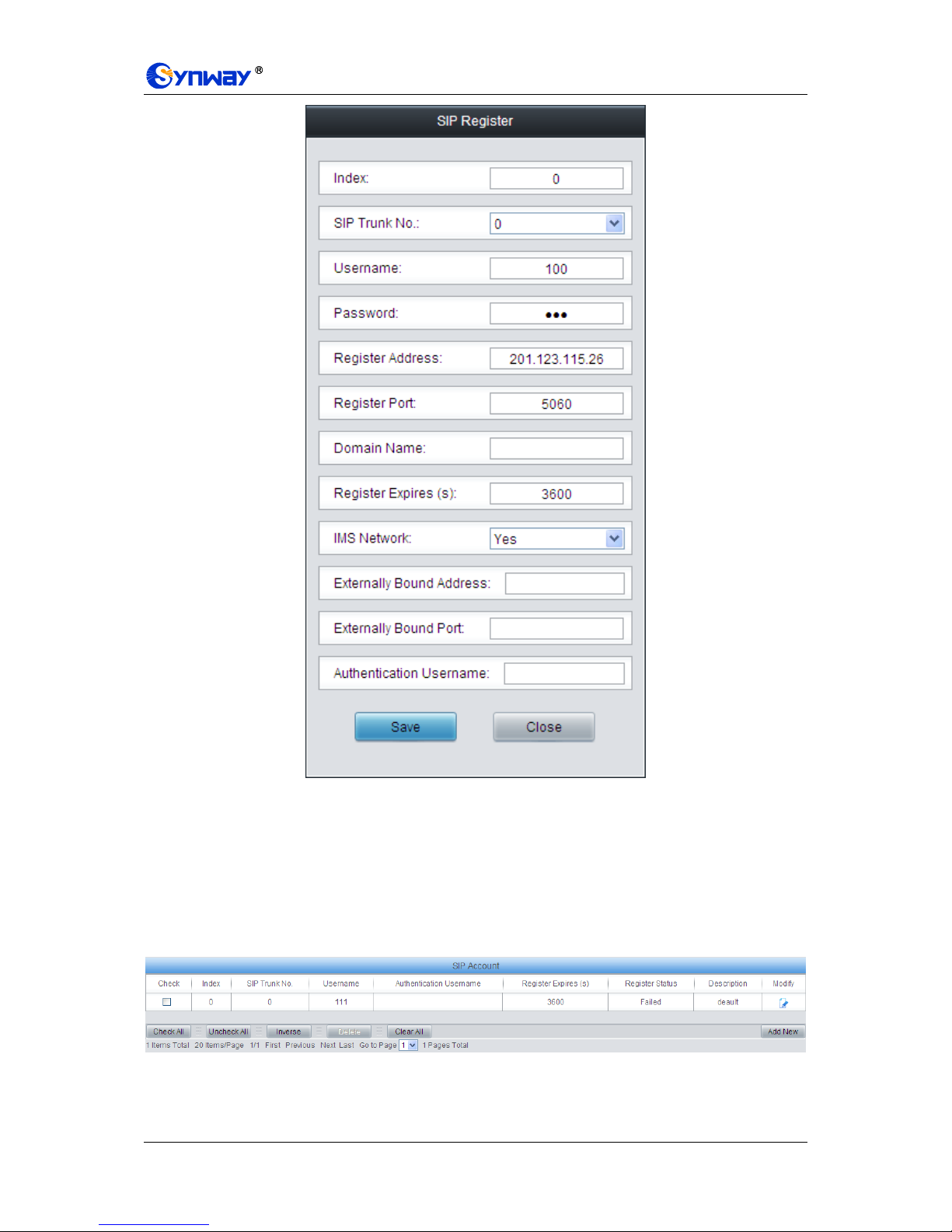
Figure 3-16 Add SIP Register Interface
The table below explains the items shown in the above figure.
Item
Description
Index
The unique index of each SIP register.
SIP Trunk No.
The number of the SIP trunk which registers to the SIP server.
Username
When the gateway initiates a call to SIP, this item corresponds to the username of
SIP; when the gateway initiates a call to PSTN, this item corresponds to the
displayed CallerID.
Password
Registration password of the gateway. To register the gateway to the SIP server,
both configuration items Username and Password should be filled in.
Register Address
Address of the SIP server to which the SIP trunk is registered.

Synway Information Engineering Co., Ltd
SMG Series Digital Gateway User Manual (Version 1.6.0) Page 29
Register Port
The signaling port of the SIP trunk.
Domain Name
Domain name of the gateway used for SIP registry.
Register Expires
Validity period of the SIP registry. Once the registry is overdue, the gateway should
be registered again. Range of value: 10~3600, calculated by s, with the default
value of 3600.
IMS Network
Once this feature is enabled, the gateway will send signaling messages to the
corresponding externally bound address and port when it registers to the server.
Only when this feature is enabled will these items Externally Bound Address,
Externally Bound Port and Authentication Username be shown.
Externally Bound
Address
Externally bound IP address for registration.
Externally Bound
Port
Externally bound port for registration.
Authentication
Username
Authentication username for registration.
After configuration, click Save to save the settings into the gateway or click Close to cancel the
settings.
Figure 3-17 SIP Register Information List
Click Modify in Figure 3-17 to modify a SIP register. The configuration items on the SIP Register
Modification Interface are the same as those on the Add New SIP Register interface.
Synway Information Engineering Co., Ltd
SMG Series Digital Gateway User Manual (Version 1.6.0) Page 30
Figure 3-18 SIP Register Modification Interface
To delete a SIP register, check the checkbox before the corresponding index in Figure 3-17 and
click the Delete button. Check All means to select all available items on the current page;
Uncheck All means to cancel all selections on the current page; Inverse means to uncheck the
selected items and check the unselected. To clear all SIP registers at a time, click the Clear All
button in Figure 3-17.
3.3.4 SIP Account
Figure 3-19 SIP Account Settings Interface
See Figure 3-19 for the SIP account settings interface. A new SIP account can be added by the
Add New button on the bottom right corner of the list in the above figure. See Figure 3-20 for the

Synway Information Engineering Co., Ltd
SMG Series Digital Gateway User Manual (Version 1.6.0) Page 31
SIP account adding interface.
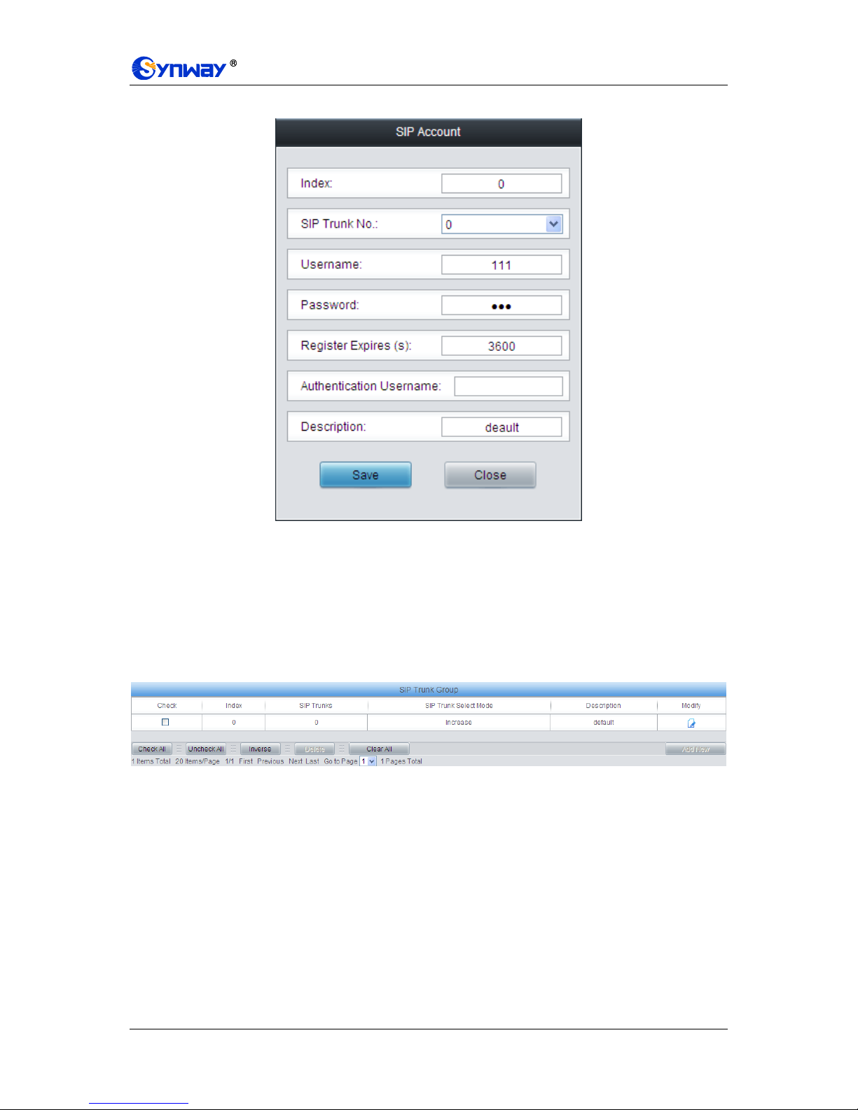
Figure 3-20 Add New SIP Account
The table below explains the items shown in above figures.
Item
Description
Index
The unique index of each SIP account.
SIP Trunk No.
The number of the SIP trunk to which the SIP account is registered.
Username
The registration username of the SIP account. Once the SIP account is successfully
registered, the SIP server can initiate calls to the gateway via Username.
Password
The registration password of the SIP account. To register the SIP account to the SIP
trunk, both configuration items Username and Password should be filled in.
Register Expires
The validity period of the SIP account registry. Once the registry is overdue, the SIP
account should be registered again. Range of value: 10~3600, calculated by s, with
the default value of 3600.
Register Status
The registration status of the SIP account. It is either Registered or Failed.
Authentication
Username
Authentication username of a port, used to register the port to the SIP server when
IMS network is enabled.
Note: This item appears only when IMS Network is enabled on the SIP trunk
corresponding to this SIP account.
Description
More information about each SIP account.
After configuration, click Save to save the settings into the gateway or click Close to cancel the
settings.
Click Modify in Figure 3-19 to modify a SIP account. See Figure 3-21 for the SIP account
modification interface. The configuration items on this interface are the same as those on the Add
Synway Information Engineering Co., Ltd
SMG Series Digital Gateway User Manual (Version 1.6.0) Page 32
New SIP Account interface.
Figure 3-21 Modify SIP Account
To delete a SIP account, check the checkbox before the corresponding index in Figure 3-19 and
click the Delete button. Check All means to select all available items on the current page;
Uncheck All means to cancel all selections on the current page; Inverse means to uncheck the
selected items and check the unselected. To clear all SIP accounts at a time, click the Clear All
button in Figure 3-19.
3.3.5 SIP Trunk Group
Figure 3-22 SIP Trunk Group Settings Interface
See Figure 3-22 for SIP trunk group settings interface. A new SIP trunk group can be added by the
Add New button on the bottom right corner of the list in the above figure. See Figure 3-23 for the
SIP trunk group adding interface.

Synway Information Engineering Co., Ltd
SMG Series Digital Gateway User Manual (Version 1.6.0) Page 33
Figure 3-23 Add New SIP Trunk Group
The table below explains the items shown in Figure 3-23.
Item
Description
Index
The unique index of each SIP trunk group, which is mainly used in the configuration
of routing rules and number manipulation rules to correspond to SIP trunk groups.
Description
More information about each SIP trunk group.
SIP Trunk Select
Mode
When the SIP trunk group receives a call, it will choose a SIP trunk based on the
select mode set by this configuration item to ring. The optional values and their
corresponding meanings are described in the table below.
Option
Description
Increase
Search for an idle SIP trunk in the ascending order of the
SIP trunk number, starting from the minimum.
Decrease
Search for an idle SIP trunk in the descending order of
the SIP trunk number, starting from the maximum.
Cyclic Increase
Provided SIP Trunk N is the available SIP trunk found last
time. Search for an idle SIP trunk in the ascending order
of the SIP trunk number, starting from SIP Trunk N+1.
Cyclic Decrease
Provided SIP Trunk N is the available SIP trunk found last
time. Search for an idle SIP trunk in the descending order
of the SIP trunk number, starting from SIP Trunk N-1.
SIP Trunks
The SIP trunks in the SIP trunk group. If the checkbox before a SIP trunk is grey, it
indicates that the SIP trunk has been occupied. The ticked SIP trunks herein will be
displayed in the column „SIP Trunks‟ in Figure 3-22.
After configuration, click Save to save the settings into the gateway or click Cancel to cancel the
settings.
Click Modify in Figure 3-22 to modify a SIP trunk group. See Figure 3-24 for the SIP trunk group
modification interface. The configuration items on this interface are the same as those on the Add
New SIP Trunk Group interface.

Synway Information Engineering Co., Ltd
SMG Series Digital Gateway User Manual (Version 1.6.0) Page 34
Figure 3-24 Modify SIP Trunk Group
To delete a SIP trunk group, check the checkbox before the corresponding index in Figure 3-22
and click the Delete button. Check All means to select all available items on the current page;
Uncheck All means to cancel all selections on the current page; Inverse means to uncheck the
selected items and check the unselected. To clear all SIP trunk groups at a time, click the Clear
All button in Figure 3-22.

Synway Information Engineering Co., Ltd
SMG Series Digital Gateway User Manual (Version 1.6.0) Page 35
3.3.6 Media Settings
Figure 3-25 Media Settings Interface
See Figure 3-25 for the media settings interface where you can configure the RTP port and
payload type depending on your requirements. After configuration, click Save to save your
settings into the gateway or click Reset to restore the configurations. If a dialog box pops up after
you save your settings asking you to restart the service, do it immediately to apply the changes.
Refer to 3.12.17 Restart for detailed instructions. The table below explains the items shown in
Figure 3-25.
Item
Description
DTMF Transmit
Mode
Sets the mode for the IP channel to send DTMF signals. The optional values are
RFC2833, In-band and Signaling, with the default value of RFC2833.
RFC2833 Payload
Payload of the RFC2833 formatted DTMF signals on the IP channel. Range of
value: 90~127, with the default value of 101.

Synway Information Engineering Co., Ltd
SMG Series Digital Gateway User Manual (Version 1.6.0) Page 36
RTP Port Range
Supported RTP port range for the IP end to establish a call conversation, with the
lower limit of 2000 and the upper limit of 60000 and the difference between larger
than 512. The default value is 6000-10000.
Silence
Suppression
Sets whether to send comfort noise packets to replace RTP packets or never to
send RTP packets to reduce the bandwidth usage when there is no voice signal
throughout an IP conversation. The optional values are Enable and Disable, with
the default value of Disable.
Note: When G723 is selected as CODEC, this configuration setting will turn to
Enable automatically.
Noise Reduction
Once this feature is enabled, the volume of the noise accompanied with the line will
be reduced automatically. The default setting is Enable.
JitterMode
Sets the working mode of JitterBuffer. The optional values are Static Mode and
Adaptive Mode, with the default value of Static Mode.
JitterBuffer
Acceptable jitter for data packets transmission over IP, which indicates the buffering
capacity. A larger JitterBuffer means a higher jitter processing capability but as well
as an increased voice delay, while a smaller JitterBuffer means a lower jitter
processing capability but as well as a decreased voice delay. Range of value:
0~280, calculated by ms, with the default value of 100.
JitterUnderrunLead
Sets the initial delay applied to received packets upon accepting packets later than
the expected value set in JitterBuffer Item. Rnage of value: 0~280, calculated by
ms, with the default value of 100,
Note: Only when JitterMode is to Static Mode will this item be shown.
JitterOverrunLead
Sets the beforehand time inserted if receiving packets is ahead of time (the time of
receiving is earlier than 300 minus the value set in JitterBuffer). Rnage of value:
0~280, calculated by ms, with the default value of 50,
Note: Only when JitterMode is to Static Mode will this item be shown.
JitterMin
Sets the minimum delay that can be set by the adaptive jitter function. It can not be
larger than the value set in JitterBuffer. Rnage of value: 0~280, calculated by ms,
with the default value of 80.
Note: Only when JitterMode is to Adaptive Mode will this item be shown.
JitterDecreaseRatio
Sets the rate of the delay that can be reduced under the adaptive mode. It defines
the maximum percentage of silence that can be removed if reducing the delay.
Rnage of value: 0~100, with the default value of 50,
Note: Only when JitterMode is to Adaptive Mode will this item be shown.
JitterIncreaseMax
Sets the maximum delay can be increased during one silence period. Rnage of
value: 0~280, calculated by ms, with the default value of 30,
Note: Only when JitterMode is to Adaptive Mode will this item be shown.
Voice Gain Output
from IP
Adjusts the voice gain of call from IP to the remote end. The value must be a
multiple of 3. Range of value: -24~24, calculated by dB, with the default value of 0.
CODEC Priority
Supported CODECs and their corresponding priority for the IP end to establish a
call conversation. The table below explains the sub-items:
Sub-item
Description
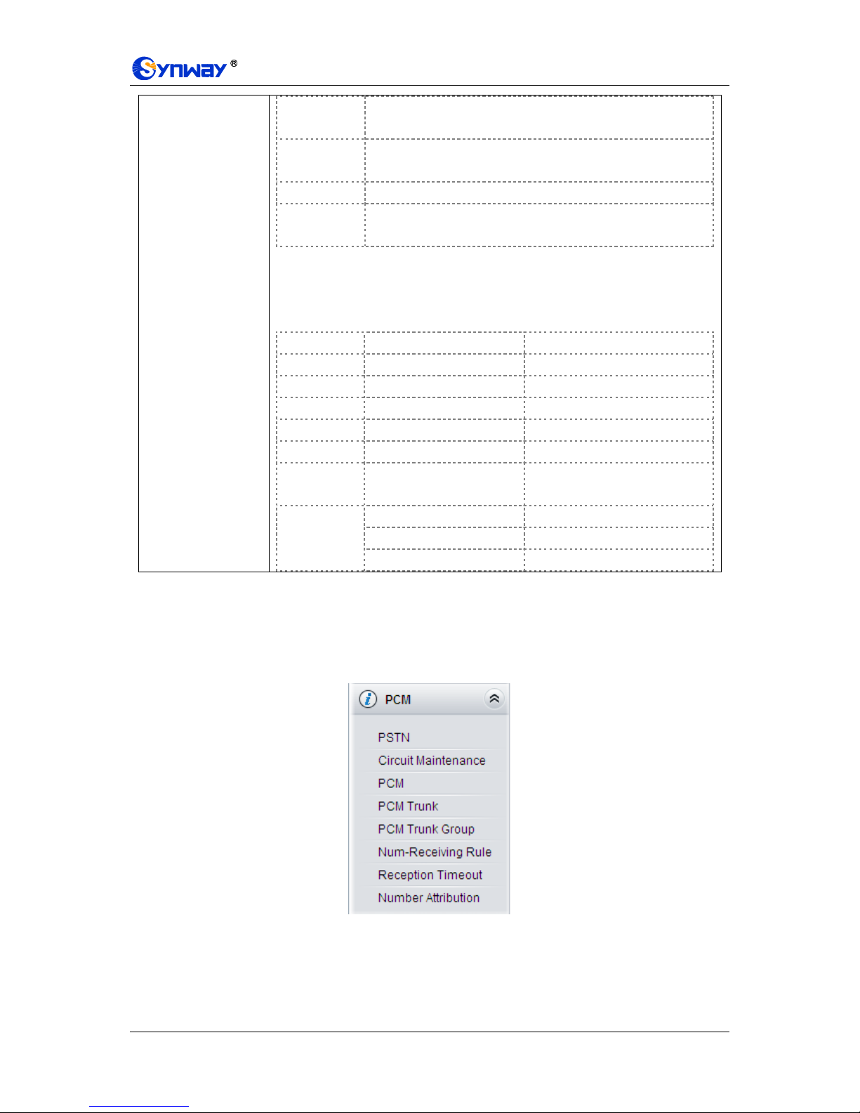
Synway Information Engineering Co., Ltd
SMG Series Digital Gateway User Manual (Version 1.6.0) Page 37
Priority
Priority for choosing the CODEC in an SIP conversation. The
smaller the value is, the higher the priority will be.
CODEC
Seven optional CODECs are supported: G711A, G711U,
G729AB, G723, G722, AMR and iLBC.
Packing Time
Time interval for packing an RTP packet, calculated by ms.
Bit Rate
The number of thousand bits (excluding the packet header) that
are conveyed per second.
By default, all of the seven CODECs are supported and ordered G711A, G711U,
G729AB, G723, G722, AMR and iLBC by priority from high to low.
The packing time and bit rate supported by different CODECs are listed in the table
below. Those values in bold face are the default values.
COEDC
Packing Time (ms)
Bit Rate (kbps)
G711A
5 / 10 / 20 / 30 / 40 / 50 / 60
64
G711U
5 / 10 / 20 / 30 / 40 / 50 / 60
64
G729AB
20 8 G723
30 / 60 / 90
5.3 / 6.3
G722
5 / 10 / 20 / 30 / 40
64
AMR
20 / 40 / 60 / 80 / 100
4.75 / 5.15 / 5.90 / 6.70 / 7.40 /
7.95 / 10.20 / 12.20
iLBC
20 / 40
15.2
30
13.3
60
13.3 / 15.2
3.4 PCM Settings
PCM Settings includes eight parts: PSTN, Circuit Maintenance, PCM, PCM Trunk, PCM Trunk
Group, Number-Receiving Rule, Reception Timeout and Number Attribution. See Figure
3-26.
Figure 3-26 PCM Settings

Synway Information Engineering Co., Ltd
SMG Series Digital Gateway User Manual (Version 1.6.0) Page 38
3.4.1 PSTN
Figure 3-27 PSTN Settings Interface
See Figure 3-27 for the PSTN Settings interface. The table below explains the items shown in the
above figure.
Item
Description
Interface
Actual type of the line connected with the E1/T1 interface on the gateway. Currently,
only E1/T1 is supported.
Encoding Format
Sets the voice data encoding format for the voice channels on the digital trunk. The
optional values are A-law and u-law, with the default value of A-law.
Echo Canceller
Sets whether to enable the echo cancellation feature for call conversations over the
digital trunk. By default, this feature is enabled and the effect can reach 128ms.
Ringback Tone
Provided by E1
Sets whether to enable the E1 end to provide the ringback tone, with the default
value of disable.
Ringback Tone
Provided by IP
Sets whether to enable the IP end to provide the ringback tone, with the default
value of disable.
Ringback Tone
Volume
Sets the volume of the ringback tone. Range of value: -35~-2, calculated by dB, with
the default value of -25.
Voice Gain Output
from PSTN
Adjusts the voice gain of call from PSTN to the remote end. The value must be a
multiple of 3. Range of value: -24~24, calculated by dB, with the default value of 0.
Hot Back-up for E1
Sets whether to enable the feature of hot back-up for E1, with the default value of
disable.
Gateway IP for Hot
Back-up
Set the IP of the gateway for the hot back-up for E1.
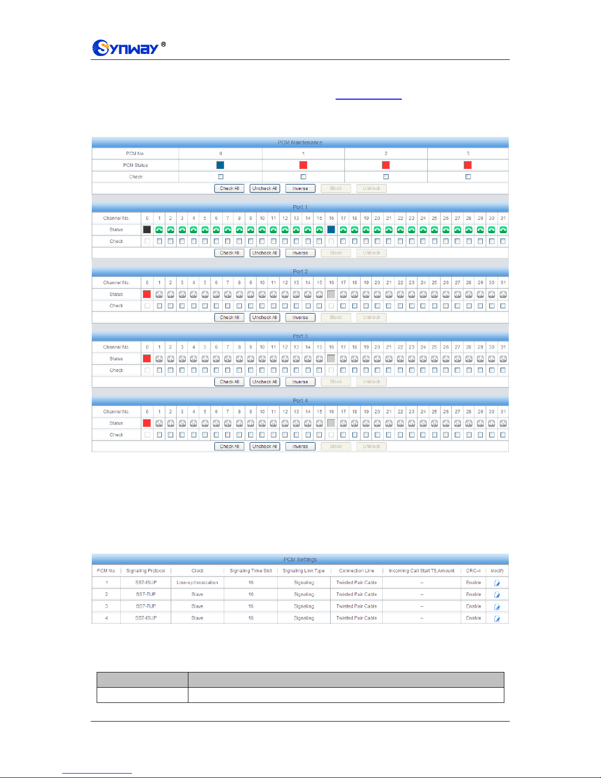
Synway Information Engineering Co., Ltd
SMG Series Digital Gateway User Manual (Version 1.6.0) Page 39
After configuration, click Save to save your settings into the gateway or click Reset to restore the
configurations. If a dialog box pops up after you save your settings asking you to restart the
service, do it immediately to apply the changes. Refer to 3.12.17 Restart for detailed instructions.
3.4.2 Circuit Maintenance
Figure 3-28 Circuit Maintenance Interface
See Figure 3-28 for the Circuit Maintenance interface. You can block or unblock PCMs, ports and
channels on this interface. Check All means to select all available items for the current port;
Uncheck All means to cancel all selections for the current port; Inverse means to uncheck the
selected items and check the unselected.
3.4.3 PCM
Figure 3-29 PCM Settings Interface
See Figure 3-29 for the PCM settings interface. The above list shows the detailed information and
configurations of each PCM. The table below explains the items shown in the above figure.
Item
Description
PCM No.
The number of the PCM, numbered from 0. This item is not configurable.

Synway Information Engineering Co., Ltd
SMG Series Digital Gateway User Manual (Version 1.6.0) Page 40
Signaling Protocol
The signaling protocol applied on the digital trunk. It includes ISDN User Side, ISDN
Network Side, SS7-TUP, SS7-ISUP, and SS1 in E1, and only includes ISDN User
Side, ISDN Network Side in T1.
Note: 1, Changing the interface type from E1 to T1 will forbid those non-ISDN
signaling modes in E1. And in such case, the gateway will by default set this
item to ISDN User Side.
2, For SMG3008, a single gateway can be configured with two different
signaling modes simultaneously.
3, For SMG3016, a single gateway can be configured with three different
signaling modes simultaneously.
Clock
The clock mode for the digital trunk, including Line-synchronization, Free-run and
Slave.
Signaling Time Slot
Sets the time slot used for signaling transmission on the digital trunk. If the
configuration item Signaling Protocol is set to ISDN and SS1, the signaling time
slot is Time Slot 16 in E1 or Time Slot 24 in T1 (SS1 not supported in T1 by far),
which cannot be modified.
Signaling Link Type
Indicates whether the PCM is used as a signaling link or a voice link. If no time slot
is used to transmit signaling, the PCM is a voice link.
Connection Line
Physical connection line type.
Incoming Call Start
TS, Amount
ets a certain amount of channels which starts from a certain TS to process the
incoming calls and others on the PCM to process outgoing calls. This is valid only
when the configuration item Signaling Protocol is set to SS1.
CRC-4
Sets whether to enable the CRC-4 verification feature. By default, this feature is
Enabled.
Click Modify in Figure 3-29 to modify a PCM. See Figure 3-30 for the PCM modification interface.
Most configuration items on this interface are the same as those on the PCM Settings interface.

Synway Information Engineering Co., Ltd
SMG Series Digital Gateway User Manual (Version 1.6.0) Page 41
Figure 3-30 Modify PCM
The table below explains the other configuration items on the PCM modification interface.
Item
Description
Use 'Signaling Time
Slot' for Signaling
If this item is checked, it indicates that the signaling time slot configured in
Signaling Time Slot is used for signaling transmission. You can see this item only
when the configuration item Signaling Protocol is set to SS7-TUP or SS7-ISUP.
Apply to All PCMs
Check this item to apply the above settings (excluding Clock) to all PCMs.
After configuration, click Save to save the settings into the gateway or click Close to cancel the
settings.
3.4.4 PCM Trunk
Figure 3-31 PCM Trunk Configuration Interface
See Figure 3-31 for the PCM Trunk Configuration interface. By default, there is no PCM trunk
available on the gateway. Click Add New or Batch Add to add them manually. See Figure 3-32,

Synway Information Engineering Co., Ltd
SMG Series Digital Gateway User Manual (Version 1.6.0) Page 42
Figure 3-33.
Figure 3-32 Add PCM Trunk Interface
Figure 3-33 PCM Trunk Batch Add Interface
The table below explains the items shown in the above figure.
Item
Description
Index
The unique index of each PCM trunk

Synway Information Engineering Co., Ltd
SMG Series Digital Gateway User Manual (Version 1.6.0) Page 43
PCM NO.
The number of the PCM, numbered from 0.
Including Ts
Sets the TS included in this PCM which can make incoming/outgoing calls.
Including PCM
Sets the PCM included in the PCM trunk.
After configuration, click Save to save the settings into the gateway or click Close to cancel the
settings.
Figure 3-34 PCM Trunks List
Click Modify in Figure 3-34 to modify a PCM trunk. The configuration items on the PCM Trunk
Modification Interface are the same as those on the Add PCM Trunk interface.
Figure 3-35 PCM Trunk Modification Interface
To delete a PCM trunk, check the checkbox before the corresponding index in Figure 3-34 and
click the Delete button. Check All means to select all available items on the current page;
Uncheck All means to cancel all selections on the current page; Inverse means to uncheck the
selected items and check the unselected. To clear all PCM trunks at a time, click the Clear All
button in Figure 3-34.

Synway Information Engineering Co., Ltd
SMG Series Digital Gateway User Manual (Version 1.6.0) Page 44
3.4.5 PCM Trunk Group
Figure 3-36 PCM Trunk Group Settings
See Figure 3-36 for the PCM trunk group settings interface. A new PCM trunk group can be added
by the Add New button on the bottom right corner of the list in the above figure. See Figure 3-37
for the PCM trunk group adding interface.
Figure 3-37 Add New PCM Trunk Group
The table below explains the items shown in Figure 3-37.
Item
Description
Index
The unique index of each PCM trunk group, which is mainly used in the
configuration of routing rules and number manipulation rules to correspond to PCM
trunk groups.
Description
More information about each PCM trunk group.
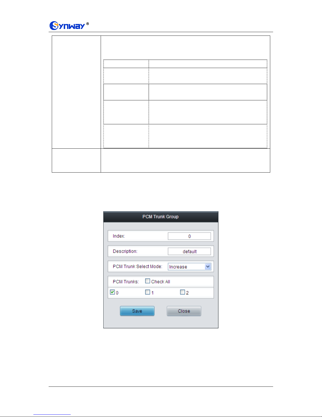
Synway Information Engineering Co., Ltd
SMG Series Digital Gateway User Manual (Version 1.6.0) Page 45
PCM Trunk Select
Mode
When the PCM trunk group receives a call, it will choose a PCM trunk based on the
select mode set by this configuration item to ring. The optional values and their
corresponding meanings are described in the table below.
Option
Description
Increase
Search for an idle PCM trunk in the ascending order of
the PCM number, starting from the minimum.
Decrease
Search for an idle PCM trunk in the descending order of
the PCM number, starting from the maximum.
Cyclic Increase
Provided PCM Trunk N is the available PCM trunk found
last time. Search for an idle PCM trunk in the ascending
order of the PCM number, starting from PCM Trunk N+1.
Cyclic Decrease
Provided PCM Trunk N is the available PCM trunk found
last time. Search for an idle PCM trunk in the descending
order of the PCM number, starting from PCM trunk N-1.
PCM Trunks
The PCM trunks in the PCM trunk group. If the checkbox before a PCM trunk is
grey, it indicates that the PCM trunk has been occupied. The ticked PCM trunks
herein will be displayed in the column „PCM Trunks‟ in Figure 3-36.
After configuration, click Save to save the settings into the gateway or click Close to cancel the
settings.
Click Modify in Figure 3-36 to modify a PCM trunk group. See Figure 3-38 for the PCM trunk
group modification interface. The configuration items on this interface are the same as those on
the Add New PCM Trunk Group interface.
Figure 3-38 Modify PCM Trunk Group
To delete a PCM trunk group, check the checkbox before the corresponding index in Figure 3-36
and click the Delete button. Check All means to select all available items on the current page;
Uncheck All means to cancel all selections on the current page; Inverse means to uncheck the
selected items and check the unselected. To clear all PCM trunk groups at a time, click the Clear
All button in Figure 3-36.

Synway Information Engineering Co., Ltd
SMG Series Digital Gateway User Manual (Version 1.6.0) Page 46
3.4.6 Number-receiving Rule
The gateway uses a number-receiving plan to filter the numbers received from PSTN. Only those
numbers which match the plan will be processed. The number-receiving plan consists of multiple
number-receiving rules, each of which has a priority in sequence to avoid conflict.
Figure 3-39 Number-Receiving Rule Configuration Interface
See Figure 3-39 for the Number-receiving Rule Configuration interface. The list in the above
figure shows the number-receiving rules with their priorities and description. A new
number-receiving rule can be added by the Add New button on the bottom right corner. See
Figure 3-40 for the number-receiving rule adding interface.
Figure 3-40 Add New Number-Receiving Rule
The table below explains the items shown in Figure 3-40.
Item
Description
Index
The unique index of each number-receiving rule, which denotes its priority. A
number-receiving rule with a smaller index value has a higher priority and will be
checked earlier while matching.

Synway Information Engineering Co., Ltd
SMG Series Digital Gateway User Manual (Version 1.6.0) Page 47
Number-Receiving
Rule
Up to 99 number-receiving rules can be configured in the gateway, and the
maximum length of each number-receiving rule is 127 characters. See below for the
meaning of each character in the number-receiving rule. The gateway will do instant
matching for your receiving number based on the number-receiving rule and regard
your receiving as finished upon receiving „#‟ or reception timeout.
Character
Description
“0”~”9”
Digits 0~9.
“x”
A random number. A string of „x‟s represents several random
numbers. For example, „xxx‟ denotes 3 random numbers.
“.”
„.‟ indicates a random amount (including zero) of characters
after it.
“[ ]”
„[ ]‟ is used to define the range for a number. Values within it only
can be digits „0~9‟, punctuations „-‟ and „,‟. For example,
[1-3,6,8] indicates any one of the numbers 1, 2, 3, 6, 8.
“-”
‟-‟ is used only in „[ ]‟ between two numbers to indicates any
number between these two numbers.
“,”
‟,‟ is used to separate numbers or number ranges, representing
alternatives.
By default, there is only one rule configured on the gateway. The table below lists 20
rules as example for your easy use and understanding. See below for detailed
information.
Priority
Dialing Rule
Description
99
.
Any number in any length.
98
01[3,5,8]xxxxxxxxx.
Any 12-digit number starting with 013,
015 or 018
97
010xxxxxxxx
Any 11-digit number starting with 010
96
02xxxxxxxxx
Any 11-digit number starting with 02
95
0[3-9]xxxxxxxxxx
Any 12-digit number starting with 03, 04,
05, 06, 07, 08 or 09
94
120
Number 120
93
11[0,2-9]
Number 110, 112, 113, 114, 115, 116, 117,
118 or 119
92
111xx
Any 5-digit number starting with 111
91
123xx
Any 5-digit number starting with 123
90
95xxx
Any 5-digit number starting with 95
89
100xx
Any 5-digit number starting with 100
88
1[3-5,8]xxxxxxxxx
Any 11-digit number starting with 13, 14,
15 or 18
87
[2-3,5-7]xxxxxxx
Any 8-digit number starting with 2, 3, 5, 6
or 7
86
8[1-9]xxxxxx
Any 8-digit number starting with 81, 82,
83, 84, 85, 86, 87, 88 or 89

Synway Information Engineering Co., Ltd
SMG Series Digital Gateway User Manual (Version 1.6.0) Page 48
85
80[1-9]xxxxx
Any 8-digit number starting with 801, 802,
803, 804, 805,.806, 807, 808 or 809
84
800xxxxxxx
Any 10-digit number starting with 800
83
4[1-9]xxxxxx
Any 8-digit number starting with 41, 42,
43, 44, 45, 46, 47, 48 or 49.
82
40[1-9]xxxxx
Any 8-digit number starting with 401, 402,
403, 404, 405, 406, 407, 408 or 409
81
400xxxxxxx
Any 10-digit number starting with 400
80
8xxx
Any 4-digit number starting with 8
Description
Remarks for the number-receiving rule. It can be any information, but can not be left
empty.
After configuration, click Save to save the above settings into the gateway or click Close to cancel
the settings.
Click Modify in Figure 3-39 to modify the number-receiving rules. See Figure 3-41 for the
number-receiving rule modification interface. The configuration items on this interface are the
same as those on the Add New Number-receiving Rule interface.
Figure 3-41 Modify Number-receiving Rule
To delete a number-receiving rule, check the checkbox before the corresponding index in Figure
3-39 and click the „Delete‟ button. Check All means to select all available items on the current
page; Uncheck All means to cancel all selections on the current page; Inverse means to
uncheck the selected items and check the unselected. To clear all number-receiving rules at a
time, click the Clear All button in Figure 3-39.
3.4.7 Reception Timeout
Figure 3-42 Number-receiving Timeout Info Interface
See Figure 3-42 for the number-receiving timeout info interface. The table below explains the

Synway Information Engineering Co., Ltd
SMG Series Digital Gateway User Manual (Version 1.6.0) Page 49
items shown in the above figure.
Item
Description
Inter Digit Timeout
Sets the largest interval between two digits of a receiving number. Range of value:
1~10, calculated by s, with the default value of 6. In case your number-receiving
rules do not include “.”, the call will fail if there is no digit received or no
number-receiving rule matched during this interval; in case your number-receiving
rules include “.”, the gateway will wait until this interval ends and match to the
number-receiving rule “.” if there is no digit received or no other number-receiving
rule matched during this interval.
Description
More information about the configuration item Inter Digit Timeout, such as the
reason for adopting the current value.
Click Modify in Figure 3-42 to modify the number-receiving timeout info. See Figure 3-43 for the
number-receiving timeout info modification interface. The configuration items on this interface are
the same as those on the Number-receiving Timeout Info Interface.
Figure 3-43 Modify Number-receiving Timeout Info
After configuration, click Save to save the above settings into the gateway or click Close to cancel
the settings.

Synway Information Engineering Co., Ltd
SMG Series Digital Gateway User Manual (Version 1.6.0) Page 50
3.4.8 Number Attribution
Figure 3-44 Number Attribution Setting Interface
See Figure 3-44 for the Number Attribution Setting interface, which is used to set whether to
remove 0 or the area code from CalleeID. Click Save to save your settings into the gateway or
click Reset to restore the configurations. Click Export to export and check the information about
the number attribution; or select the required number attribution file via Browse… and click
Import to import it into the gateway.
Note: By far only those numbers with the start 13x, 14x, 15x, 17x, or 18x can be imported.
3.5 SS7 Settings
Users can see the SS7 option in the menu only when the configuration item Signaling Protocol
on the PCM settings interface is set to SS7-TUP or SS7-ISUP. SS7 Settings includes eight parts:
SS7, TUP, TUP Number Param, ISUP, Number Param, Original CalleeID Pool, Redirecting
Number Pool and SS7 Server. See Figure 3-45.

Synway Information Engineering Co., Ltd
SMG Series Digital Gateway User Manual (Version 1.6.0) Page 51
Figure 3-45 SS7 Settings
3.5.1 SS7
Figure 3-46 SS7 Settings Interface
See Figure 3-46 for the SS7 settings interface where you can configure the general SS7
parameters. After configuration, click Save to save your settings into the gateway or click Reset to
restore the configurations. If a dialog box pops up after you save your settings asking you to
restart the service, do it immediately to apply the changes. Refer to 3.12.17 Restart for detailed
instructions. The table below explains the items shown in Figure 3-46.
Item
Description
As Client Only
Sets whether the gateway serves as Client only or not. If it is set to No (default), the
SS7 server will be disabled.
Master IP
Sets the IP address of the master SS7 server, with the default value of 127.0.0.1,
which indicates that there is only one SS7 server available.
Slave IP
Sets the IP address of the slave SS7 server. Only when the item Dual Gateway is
ticked can this item be configured.
Local IP Address
Sets the IP address of the local PC, with the default value of 127.0.0.1.
Dual Gateway
If this feature is enabled, two SS7 servers are used at the same time in the system.
The configuration items Master IP and Slave IP are respectively used to set the IP
addresses of the master and slave servers.
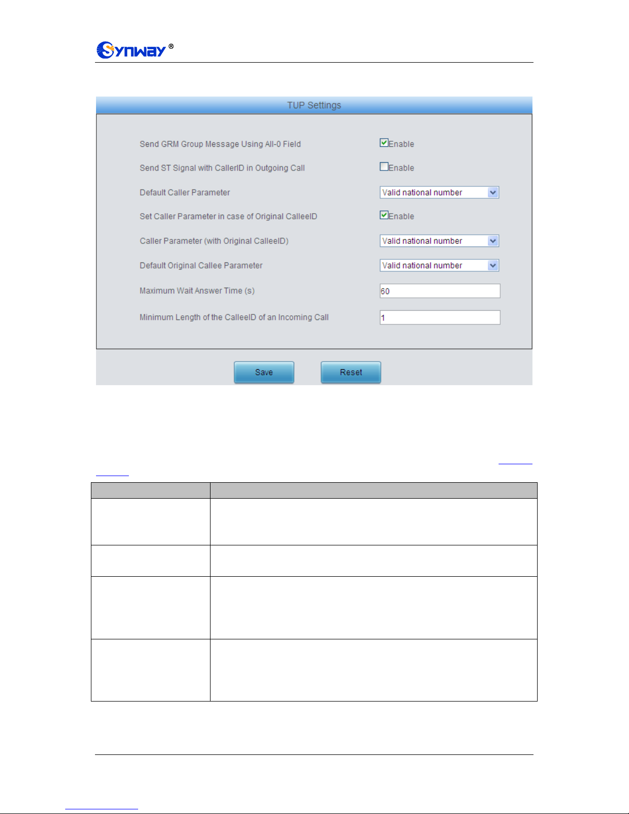
Synway Information Engineering Co., Ltd
SMG Series Digital Gateway User Manual (Version 1.6.0) Page 52
3.5.2 TUP
Figure 3-47 TUP Settings Interface
See Figure 3-47 for the TUP settings interface. Users can see this interface and configure the
general TUP parameters only when the configuration item Signaling Protocol on the PCM
settings interface is set to SS7-TUP. After configuration, click Save to save your settings into the
gateway or click Reset to restore the configurations. If a dialog box pops up after you save your
settings asking you to restart the service, do it immediately to apply the changes. Refer to 3.12.17
Restart for detailed instructions. The table below explains the items shown in Figure 3-47.
Item
Description
Send GRM Group
Message Using All-0 Field
If this configuration item is enabled, when the local driver sends the circuit group
message to the remote PBX, this message covers all time slots TS1~31. By default
this item is enabled.
Send ST Signal with
CallerID in Outgoing Call
If this configuration item is enabled, the calling party number string sent by the
gateway contains the ST signal in the outgoing call. By default this item is disabled.
Default Caller Parameter
Sets the address indicator in the calling line identification field in the IAI message.
The optional values are: Local subscriber number, Spare national number, Valid
national number and International number, with the default value of Valid national
number.
Set Caller Parameter in
case of Original CalleeID
Once this feature is enabled, if the IP end carries the original CalleeID in a call from
IP to PSTN, you shall set a separate value for the address indicator in the calling
line identification field in the IAI message, i.e. Caller Parameter ( with Original
CalleeID). By default this configuration item is disabled.

Synway Information Engineering Co., Ltd
SMG Series Digital Gateway User Manual (Version 1.6.0) Page 53
Caller Parameter (with
Original CalleeID)
This item is valid only when Set Caller Parameter in case of Original CalleeID is
enabled. It sets the address indicator in the calling line identification field in the IAI
message when the IP end carries the original CalleeID in a call from IP to PSTN.
The optional values are: Local subscriber number, Spare national number, Valid
national number and International number, with the default value of Valid national
number.
Default Original Callee
Parameter
Sets the address indicator in the original called party address field of the IAI
message. The optional values are: Local subscriber number, Spare national
number, Valid national number and International number, with the default value of
Valid national number.
Maximum Wait Answer
Time (s)
Sets the maximum time to wait for the answer from the called party of an outgoing
call. If the call is not answered within the specified time period, it will be canceled
by the channel automatically. The default value is 60, calculated by s.
Minimum Length of the
CalleeID of an Incoming
Call
Sets the minimum length of the CalleeID under the fixed-length mode. The value
range is 1n40. Provided it is set to n, that is, the local end has received all the n
digits of the called party number of the incoming call, the number reception will be
regarded as finished.
3.5.3 TUP Number Parameter
Figure 3-48 TUP Number Parameter Configuration Interface
See Figure 3-48 for the TUP Number Parameter Configuration interface, which is used to set the
corresponding parameters for the calling party number in TUP.
A new TUP number parameter can be added by the Add New button. See Figure 3-49 for the
calling party number adding interface.
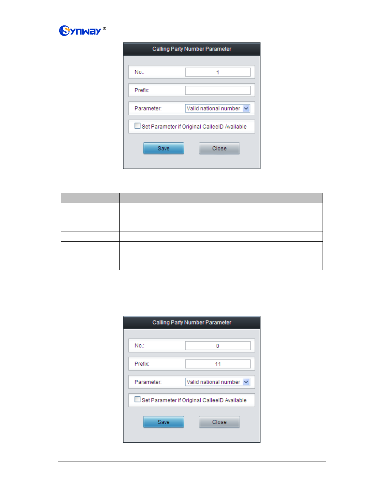
Synway Information Engineering Co., Ltd
SMG Series Digital Gateway User Manual (Version 1.6.0) Page 54
Figure 3-49 Add New Calling Party Number Parameter
The table below explains the items shown in the above figure.
Item
Description
No.
The corresponding number for a calling party number parameter, which starts from
0.
Prefix
A string of numbers at the beginning of a calling party number.
Parameter
Sets the parameter for a calling party number.
Set Parameter if
Original CalleeID
Available
Set whether to enable the feature of setting this parameter only if the original
CalleeID is available.
After configuration, click Save to save the above settings into the gateway or click Close to cancel
the settings.
Click Modify in Figure 3-48 to modify the calling party number parameter. See Figure 3-50 for the
calling party number parameter modification interface. The configuration items on this interface
are the same as those on the Add New Calling Party Number Parameter interface.
Figure 3-50 Modify Calling Party Number Parameter
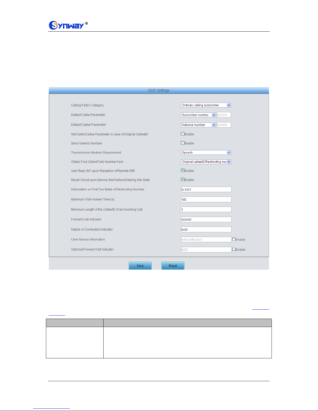
Synway Information Engineering Co., Ltd
SMG Series Digital Gateway User Manual (Version 1.6.0) Page 55
To delete a calling party number parameter, check the checkbox before the corresponding index
in Figure 3-48 and click the „Delete‟ button. To clear all calling party number parameters at a time,
click the Clear All button in Figure 3-48.
Note: If there are two or more calling party numbers with the same prefix, the one numbered the
smallest is valid and all the others become invalid.
3.5.4 ISUP
Figure 3-51 ISUP Settings Interface
See Figure 3-51 for the ISUP settings interface. Users can see this interface and configure the
general ISUP parameters only when the configuration item Signaling Protocol on the PCM
settings interface is set to SS7-ISUP. After configuration, click Save to save your settings into the
gateway or click Reset to restore the configurations. If a dialog box pops up after you save your
settings asking you to restart the service, do it immediately to apply the changes. Refer to 3.12.17
Restart for detailed instructions. The table below explains the items shown in Figure 3-51.
Item
Description
Calling Party’s Category
Sets the calling party‟s category indicator in the IAM message. The optional values
are: National operator, Ordinary calling subscriber, Calling subscriber with priority,
Data call, Test call and Payphone/Others, with the default value of Ordinary calling
subscriber.

Synway Information Engineering Co., Ltd
SMG Series Digital Gateway User Manual (Version 1.6.0) Page 56
Default Caller Parameter
Sets the calling party number parameter field in the IAM message. The optional
values are: Subscriber number, National number, and International number, with the
default value of Subscriber number.
Default Callee Parameter
Sets the called party number parameter field in the IAM message. The optional
values are: Subscriber number, National number, and International number, with the
default value of National number.
Set Caller/Callee
Parameter in case of
Original CalleeID
Once this feature is enabled, if the IP end carries the original CalleeID in a call from
IP to PSTN, you shall set separate values for the caller and callee parameters in the
IAM message, i.e. Caller Parameter (with Original CalleeID) and Callee
Parameter (with Original CalleeID). By default this configuration item is disabled.
Caller Parameter (with
Original CalleeID)
This item is valid only when Set Caller/Callee Parameter in case of Original
CalleeID is enabled. It sets the calling party number parameter field in the IAM
message when the IP end carries the original CalleeID in a call from IP to PSTN.
The optional values are: Subscriber number, National number, and International
number, with the default value of Subscriber number.
Callee Parameter (with
Original CalleeID)
This item is valid only when Set Caller/Callee Parameter in case of Original
CalleeID is enabled. It sets the called party number parameter field in the IAM
message when the IP end carries the original CalleeID in a call from IP to PSTN.
The optional values are: Subscriber number, National number, and International
number, with the default value of National number.
Send Generic Number
Sets the generic number parameter in IAM message, with the default value of
disabled.
Transmission Medium
Requirement
Sets the transmission medium requirement parameter in the IAM message. The
optional values are: Speech, 64 kb/s unrestricted, 3.1khz audio, Alternative: speech
(service 2)/ 64kbit/s unrestricted (service 1) (Spare), Alternative: 64kbit/s
unrestricted (service 1)/ speech (service 2) (Spare), 64kb/s preferred, 2*64kb/s
unrestricted, 384 kb/s unrestricted, 1920 kb/s unrestricted and Spare, with the
default value of Speech.
Obtain First Called Party
Number from
Sets where the first called party number is obtained from. The optional values are:
Only original CalleeID and Original CalleeID/ Redirecting number, with the default
value of Only original CalleeID.
Auto Reply INF upon
Reception of Remote
INR
If this feature is enabled, once the INR message is received from the remote PBX in
an outgoing call, the driver will automatically reply it with the INF message. By
default this feature is enabled.
Reset Circuit upon
Service Start before
Entering Idle State
If this feature is enabled, the circuit will send a circuit reset message before entering
the idle state after the ISUP service is enabled. By default this feature is enabled.
Information on First Two
Bytes of Redirecting
Number
Sets the first two bytes of the redirecting number in the IAM message, including the
nature of address indicator, numbering plan indicator and address presentation
restricted indicator, with the default value of 0x1001.
Maximum Wait Answer
Time (s)
Sets the maximum time to wait for the answer from the called party of an outgoing
call. If the call is not answered within the specified time period, it will be canceled by
the channel automatically. The default value is 180, calculated by s.

Synway Information Engineering Co., Ltd
SMG Series Digital Gateway User Manual (Version 1.6.0) Page 57
Minimum Length of the
CalleeID of an Incoming
Call
Sets the minimum length of the CalleeID under the fixed-length mode. The value
range is 1n40. Provided it is set to n, that is, the local end has received all the n
digits of the called party number of the incoming call, the number reception will be
regarded as finished.
Forward Call Indicator
Sets the forward call indicator in the IAM message, with the default value of 0x0040.
Nature of Connection
Indicator
Sets the nature of connection indicator in the IAM message, with the default value of
0x00.
User Service Information
Sets whether the IAM message contains the user service information. By default this
feature is disabled. If this feature is enabled, its value is usually determined by the
remote PBX, with the default value of 0x80, 0x90, 0xa3. This default value is
applicable to Huawei PBXes.
Optional Forward Call
Indicator
Sets whether the IAM message contains the optional forward call indicator. By
default this feature is disabled. If this feature is enabled, its value is usually
determined by the remote PBX, with the default value of 0x00.
3.5.5 ISUP Number Parameter
Figure 3-52 ISUP Number Parameter Configuration Interface
See Figure 3-52 for the ISUP Number Parameter Configuration interface, which includes two
parts: Calling Party Number Parameter and Called Party Number Parameter.
A new calling/called party number parameter can be added by the Add New button. See Figure
3-53, Figure 3-54 for the calling/called party number parameter adding interface.

Synway Information Engineering Co., Ltd
SMG Series Digital Gateway User Manual (Version 1.6.0) Page 58
Figure 3-53 Add New Calling Party Number Parameter
Figure 3-54 Add New Called Party Number Parameter
The table below explains the items shown in above figures.
Item
Description
No.
The corresponding number for a calling/called party number parameter, which starts
from 0.
Prefix
A string of numbers at the beginning of a calling/called party number.
Parameter
Sets the parameter for a calling/called party number.
Set Parameter if
Original CalleeID
Available
Set whether to enable the feature of setting this parameter only if the original
CalleeID is available.
After configuration, click Save to save the above settings into the gateway or click Close to cancel
the settings.

Synway Information Engineering Co., Ltd
SMG Series Digital Gateway User Manual (Version 1.6.0) Page 59
Click Modify in Figure 3-52 to modify the calling/called party number parameter. See Figure 3-55,
Figure 3-56 for the calling/called party number parameter modification interface. The configuration
items on this interface are the same as those on the Add New Calling/Called Party Number
Parameter interface.
Figure 3-55 Modify Calling Party Number Parameter
Figure 3-56 Modify Called Party Number Parameter
To delete a calling/called party number parameter, check the checkbox before the corresponding
index in Figure 3-52 and click the „Delete‟ button. To clear all calling/called party number
parameters at a time, click the Clear All button in Figure 3-52.
Note: If there are two or more calling/called party numbers with the same prefix, the one
numbered the smallest is valid and all the others become invalid.

Synway Information Engineering Co., Ltd
SMG Series Digital Gateway User Manual (Version 1.6.0) Page 60
3.5.6 Original CalleeID Pool
Figure 3-57 Original CalleeID Pool Interface
See Figure 3-57 for the Original CalleeID Pool interface, which is used to add the original CalleeID
for all outgoing calls or some special calls which contain the specified calling/called prefix.
A new original CalleeID can be added by the Add New button. See Figure 3-58 for the original
CalleeID adding interface.
Figure 3-58 Add New Original CallerID
The table below explains the items shown in above figures.
Item
Description
No.
The corresponding number for an added original CalleeID. The value range is 0~99.
CallerID Prefix
A string of numbers at the beginning of a calling party number, which can be
numbers or “*” (indicating any string).
CalleeID Prefix
A string of numbers at the beginning of a called party number, which can be
numbers or “*” (indicating any string).

Synway Information Engineering Co., Ltd
SMG Series Digital Gateway User Manual (Version 1.6.0) Page 61
Original CalleeID
Range
The range of the original CalleeID in the Original CalleeID Pool. It must be filled in
with numbers and can not be left empty.
After configuration, click Save to save the above settings into the gateway or click Close to cancel
the settings.
Click Modify in Figure 3-57 to modify the calling/called party number parameter. See Figure 3-59,
for the original CalleeID modification interface. The configuration items on this interface are the
same as those on the Add New Original CalleeID interface. Note that the item No. cannot be
modified.
Figure 3-59 Modify Original CalleeID
Note: If there are two or more calling/called party numbers with the same prefix, Starting Original
CalleeID and Number Amount corresponding to the one numbered the smallest are valid and all
the others become invalid.
3.5.7 Redirecting Number Pool
Figure 3-60 Redirecting Number Pool Interface
See Figure 3-60 for the Redirecting Number Pool interface, which is used to set the redirecting
number in the setup message for all outgoing calls or some calls which contain a specified

Synway Information Engineering Co., Ltd
SMG Series Digital Gateway User Manual (Version 1.6.0) Page 62
calling/called prefix. This feature is only applicable to ISUP calls.
A new redirecting number can be added by the Add New button. See Figure 3-61 for the
redirecting number adding interface.
Figure 3-61 Add New Redirecting Number
The table below explains the items shown in above figures.
Item
Description
No.
The corresponding number for an added redirecting number. The value range is
0~99.
CallerID Prefix
A string of numbers at the beginning of a calling party number, which can be
numbers or “*” (indicating any string).
CalleeID Prefix
A string of numbers at the beginning of a called party number, which can be
numbers or “*” (indicating any string).
Redirecting
Information
Sets the redirection information field in the IAM message. The parameter type of the
redirection information field is 0x13, which contains 2 bytes. By default, it is set to
0x0321, i.e. call forwarding on no answer. Refer to the ISUP protocol standard for
the detailed description of each byte.
Redirecting Number
Range
The range of the redirecting number in the Redirecting Number Pool. It must be filled
in with numbers and can not be left empty.
After configuration, click Save to save the above settings into the gateway or click Close to cancel
the settings.
Click Modify in Figure 3-60 to modify the redirecting number parameter. See Figure 3-62 for the
redirecting number modification interface. The configuration items on this interface are the same
as those on the Add New Redirecting Number interface. Note that the item No. cannot be
modified.

Synway Information Engineering Co., Ltd
SMG Series Digital Gateway User Manual (Version 1.6.0) Page 63
Figure 3-62 Modify Redirecting Number
To delete a redirecting number parameter, check the checkbox before the corresponding index in
Figure 3-60 and click the „Delete‟ button. To clear all redirecting number parameters at a time,
click the Clear All button in Figure 3-60.
Note: If there are two or more calling/called party numbers with the same prefix, only the one
numbered the smallest are valid for Starting Redirecting Number and Number Amount.
3.5.8 SS7 Server
Figure 3-63 SS7 Server Configuration Interface
When the gateway uses the SS7 signaling, it must run the SS7 server first. See Figure 3-63 for
the SS7 configuration interface, where you can set the SS7 server configuration file
(Ss7server.ini). Follow the instructions below to accomplish the configurations step by step.

Synway Information Engineering Co., Ltd
SMG Series Digital Gateway User Manual (Version 1.6.0) Page 64
Step 1: Set Server IP and Signaling Point Code Standard. See Region 1 in Figure 3-63.
The table below explains these configuration items.
Item
Description
Server 1 IP
Sets the IP address for the master SS7 server. If only one server is used in the
system, there is no need to set the configuration item Server 2 IP.
Server 2 IP
Sets the IP address for the slave SS7 server.
Signaling Point
Code Standard
The value of this item varies on the PBX model. The optional values are 14 and 24,
with the default value of 24. The China SS7 uses 24.
Subservice Code
Sets the SS7 subservice code. The optional values are: International network,
Spare international network, National network, Spare national network, with the
default value of Spare national network.
Send SLTM
Sets whether to regularly send the Signaling Link Test Message (SLTM) to the
remote PBX. By default it is disabled.
After configuration, click Save to save the settings into the gateway.
Step 2: Configure the client. See Region 2 in Figure 3-63.
A new client can be added by the Add New button on the bottom right corner of the client list. See
Figure 3-64 for the new client adding interface.
Figure 3-64 Add New Client
The table below explains the configuration items in the above figure.
Item
Description
No.
The unique index of each client, which is mainly used in the configuration of
signaling links to correspond to the client, numbered from 0.
IP Address
IP address of the client.
After configuration, click Save to save the settings into the gateway or click Close to cancel the
settings.
To modify a client, click Modify in the client list. The configuration items on the modification
interface are the same as those on the Add New Client interface.
To delete a client, check the checkbox before the corresponding index and click the Delete button
under the list. To clear all clients at a time, click the Clear All button. Note: If a client is occupied
by a signaling link, it cannot be deleted or cleared unless you delete the signaling link first. You
can only delete the clients in turn from back to front.
Step 3: Configure signaling links and linksets. See Region 3 in Figure 3-63.
The link used to transmit signaling messages between two signaling points is called Signaling

Synway Information Engineering Co., Ltd
SMG Series Digital Gateway User Manual (Version 1.6.0) Page 65
Link. Each signaling link maps a physical address. A new signaling link can be added by the Add
New button on the bottom right corner of the signaling link list. See Figure 3-65 for the new
signaling link adding interface.
Figure 3-65 Add New Signaling Link
The table below explains the configuration items in the above figure.
Item
Description
No.
The unique index of each signaling link, which is mainly used in the configuration of
signaling linksets to correspond to the signaling link, numbered from 0.
Client
Client number. This configuration item together with PCM determines the physical
address of the E1 interface of the signaling link. Each physical address maps a
signaling link.
PCM
Local PCM number. This configuration item together with Client determines the
physical address of the E1 interface of the signaling link.
After configuration, click Save to save the settings into the gateway or click Close to cancel the
settings.
To modify a signaling link, click Modify in the signaling link list. The configuration items on the
modification interface are the same as those on the Add New Signaling Link interface.
To delete a signaling link, check the checkbox before the corresponding index and click the
Delete button under the list. To clear all signaling links at a time, click the Clear All button. Note: If
a signaling link is occupied by a signaling linkset, it cannot be deleted or cleared unless you delete
the signaling linkset first. You can only delete the signaling links in turn from back to front.
A group of signaling links used to connect two signaling points directly constitute a signaling
linkset. A new signaling linkset can be added by the Add New button on the bottom right corner of
the signaling linkset list. See Figure 3-66 for the new signaling linkset adding interface.

Synway Information Engineering Co., Ltd
SMG Series Digital Gateway User Manual (Version 1.6.0) Page 66
Figure 3-66 Add New Signaling Linkset
The table below explains the configuration items in the above figure.
Item
Description
No.
The unique index of each signaling linkset, which is mainly used in the configuration
of DPC to correspond to the signaling linkset, numbered from 0.
Link
The signaling links in the linkset. If the checkbox before a link is grey, it indicates
that the link has been occupied.
OPC
Originating Point Code for the signaling server which is usually allocated by the
central office,. See the table below for the format and the value range:
14 bit
24 bit
Decimal (a.b.c)
a, c: 0~7, b: 0~255
a, b, c: 0~255
Hexadecimal
(abc)
a, c: 3-digit hexadecimal number,
b: 8-digit hexadecimal number
a, b, c: hexadecimal
number inbetween 00~ff
After configuration, click Save to save the settings into the gateway or click Close to cancel the
settings.
To modify a signaling linkset, click Modify in the signaling linkset list. The configuration items on
the modification interface are the same as those on the Add New Signaling Linkset interface.
To delete a signaling linkset, check the checkbox before the corresponding index and click the
Delete button under the list. To clear all signaling linkset at a time, click the Clear All button. Note:
If a signaling linkset is occupied by a DPC, it cannot be deleted or cleared unless you delete the
DPC first. You can only delete the signaling linksets in turn from back to front.
Step 4: Configure DPC. See Region 4 in Figure 3-63.
The signaling point that receives messages is called Destination Point Code (DPC). A new DPC
can be added by the Add New button on the bottom right corner of the DPC list. See Figure 3-67
for the new DPC adding interface.
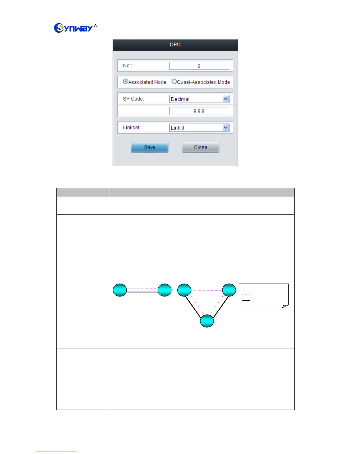
Synway Information Engineering Co., Ltd
SMG Series Digital Gateway User Manual (Version 1.6.0) Page 67
Figure 3-67 Add New DPC
The table below explains the configuration items in the above figure.
Item
Description
No.
The unique index of each DPC, which is mainly used in the configuration of
TUP_CIC Route or ISUP_CIC Route to correspond to the DPC, numbered from 0.
Associated Mode/
Quasi-associated
Mode
Sets the way to transmit signaling messages between two signaling points,
including Associated Mode and Quasi-associated Mode. Directly connecting the
signaling links between two signaling points to transmit the inbetween signaling
messages is called Associated Mode. Connecting two or more than two signaling
links serially via one or more than one signaling transport points to transmit
signaling messages, provided the path of signaling messages through the signaling
network is predetermined and fixed within a certain period of time, is called
Quasi-associated Mode. These two concepts are vividly illustrated below.
SP Code
Signaling point code of the DPC, usually allocated by the central office.
STP
Sets the first STP (signaling transport point) the signaling message reaches during
the transmission under the quasi-associated mode. Only when you select the
quasi-associated mode can this item be seen and configured.
Linkset
The linkset which is used to transmit signaling messages. For the associated mode,
this item sets the signaling linksets between the OPC and the DPC. For the
quasi-associated mode, this item sets the signaling linksets between the OPC and
the first STP (signaling transport point).
Legend:
Signaling Relationship
Signaling Link Set
SP
SP
SP
SP
STP
(a) Associated Mode
(b) Quasi-associated Mode
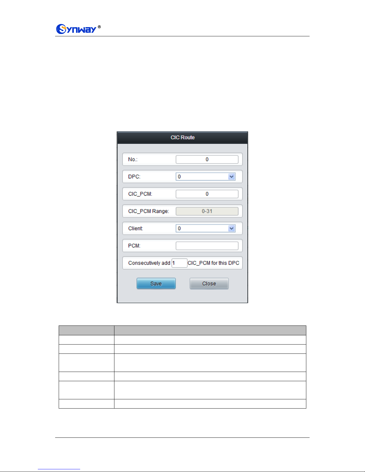
Synway Information Engineering Co., Ltd
SMG Series Digital Gateway User Manual (Version 1.6.0) Page 68
After configuration, click Save to save the settings into the gateway or click Close to cancel the
settings.
To modify a DPC, click Modify in the DPC list. The configuration items on the modification
interface are the same as those on the Add New DPC interface.
To delete a DPC, check the checkbox before the corresponding index and click the Delete button
under the list. To clear all DPCs at a time, click the Clear All button. Note: If a DPC is occupied by
a CIC routing rule, it cannot be deleted or cleared unless you delete the routing rule first. You can
only delete the DPCs in turn from back to front.
Step 5: Configure TUP_CIC or ISUP_CIC Route. See Region 5 in Figure 3-63.
A new TUP_CIC routing rule can be added by the Add New button on the bottom right corner of
the TUP_CIC routing rule list. See Figure 3-68 for the new TUP_CIC routing rule adding interface.
Figure 3-68 Add New TUP_CIC Routing Rule
The table below explains the configuration items in the above figure.
Item
Description
No.
The unique index of each CIC routing rule, which is numbered from 0.
DPC
DPC used in the routing rule.
CIC_PCM
PCM number in the CIC field and the value is obtained by dividing the initial CIC
number from the central office by 32.
CIC_PCM Range
Range of the PCM time slots corresponding to CIC.
Client
Client number. This configuration item together with PCM determines the local PCM
in the CIC routing rule.
PCM
PCM number on the client.
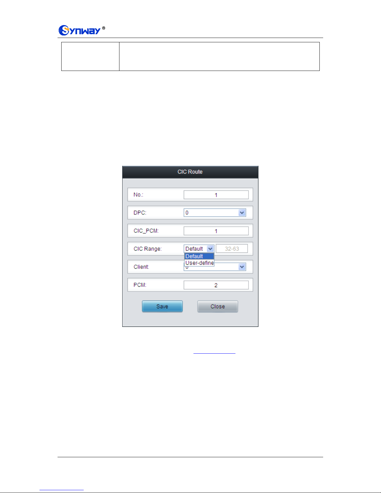
Synway Information Engineering Co., Ltd
SMG Series Digital Gateway User Manual (Version 1.6.0) Page 69
Consecutively add
_CIC_PCM for this
DPC
Consecutively adds one or more CIC_PCM routes for a DPC.
After configuration, click Save to save the settings into the gateway or click Close to cancel the
settings.
To modify a routing rule, click Modify in the TUP_CIC routing rule list. The configuration items on
the modification interface are the same as those on the Add New TUP_CIC Routing Rule
interface.
To delete a routing rule, check the checkbox before the corresponding index and click the Delete
button under the list. To clear all routing rules at a time, click the Clear All button.
For the ISUP_CIC route settings, click the ISUP_CIC Route tab in Region 5 in Figure 3-63. See
Figure 3-69 for the ISUP_CIC route settings interface. The configuration items and operations on
this interface are absolutely the same as those in the TUP_CIC route settings interface. Note:
Besides the default setting, the CIC Range for ISUP_CIC route can also be user-defined.
Figure 3-69 ISUP_CIC Route Settings Interface
After completing the configurations on SS7 Server Configuration Interface (Figure 3-63), you
shall restart the service to validate them. Refer to 3.12.17 Restart for detailed instructions.
3.6 ISDN Settings
Users can see the ISDN option in the menu only when the configuration item Signaling Protocol
on the PCM settings interface is set to ISDN User Side or ISDN Network Side. See Figure 3-70.

Synway Information Engineering Co., Ltd
SMG Series Digital Gateway User Manual (Version 1.6.0) Page 70
Figure 3-70 ISDN Settings
3.6.1 ISDN
Figure 3-71 ISDN Settings Interface
See Figure 3-71 for the ISDN settings interface where users can configure the general ISDN
parameters. After configuration, click Save to save your settings into the gateway or click Reset to
restore the configurations. If a dialog box pops up after you save your settings asking you to
restart the service, do it immediately to apply the changes. Refer to 3.12.17 Restart for detailed
instructions. The table below explains the items shown in Figure 3-71.
Item
Description
TEI
Terminal Equipment Identifier, which is used to identify the service access point in
the point-to-point data link connection. Range of value: 0~63, with the default value
of 0. Note: The TEI values at the corresponding user side and the network side must
be the same.
Ch Identification
Sets the way to represent channel identification messages on the digital trunk. The
optional values are: Number and Time slot diagram, with the default value of
Number.

Synway Information Engineering Co., Ltd
SMG Series Digital Gateway User Manual (Version 1.6.0) Page 71
Default Callee Type
Sets the type of number and numbering scheme for the called party numbers in the
SETUP message during the outgoing call. The optional values are: National number,
International number, Network number, Subscriber number and Unknown, with the
default value of National number.
Default Caller Type
Sets the type of number and numbering scheme for the calling party numbers in the
SETUP message during the outgoing call. The optional values are: National number,
International number, Network number, Subscriber number and Unknown, with the
default value of National number.
CODEC
Sets the voice CODEC used on the digital trunk. The optional values are A-Law and
u-Law, with the default value of A-Law.
CRC Check
Sets whether to enable the feature of CRC check for the digital trunk at ISDN user
side or network side. By default this feature is enabled.
Set Caller/Callee Type in
case of Redirecting Num
Once this feature is enabled, if the IP end carries the redirecting number in a call
from IP to PSTN, you shall set separate values for the type of number and
numbering scheme for the calling and called party numbers in the SETUP message,
i.e. Callee Type (with Redirecting Num) and Caller Type (with Redirecting
Num). By default this configuration item is disabled.
Callee Type (with
Redirecting Num)
This item is valid only when Set Caller/Callee Type in case of Redirecting Num is
enabled. It sets the type of number and numbering scheme for the called party
numbers in the SETUP message when the IP end carries the redirecting number in
a call from IP to PSTN. The optional values are: National number, International
number, Network number, Subscriber number and Unknown, with the default value
of National number.
Caller Type (with
Redirecting Num)
This item is valid only when Set Caller/Callee Type in case of Redirecting Num is
enabled. It sets the type of number and numbering scheme for the calling party
numbers in the SETUP message when the IP end carries the redirecting number in
a call from IP to PSTN. The optional values are: National number, International
number, Network number, Subscriber number and Unknown, with the default value
of National number.
Transfer Capability
Sets the „Transfer Capability‟ filed in the signaling message. The optional values are
Voice and 3.1k Audio, with the default value of Voice.
Enter Auto Alert State
upon Reception of
'CALL PROCEEDING'
Message
If this item is checked, the system will go into the state of auto alert when it receives
the 02 (CALL PROCEEDING) message and the progress indicator turns to be 8 or
1. By default this item is disabled.
Enter Auto Alert State
upon Reception of
'PROGRESS' Message
If this item is checked, the system will go into the state of auto alert when it receives
the 03 (PROGRESS) message and the progress indicator turns to be 8 or 1. By
default this item is disabled.
Maximum Wait Time for
Called Party’s Pick up
The maximum time waiting for the called party to pick up the call after the channel
state turns to „WaitAnswer‟ during an outgoing call. The default value is 60,
calculated by s.

Synway Information Engineering Co., Ltd
SMG Series Digital Gateway User Manual (Version 1.6.0) Page 72
Minimum Length of the
CalleeID of an Incoming
Call
Sets the minimum length of the CalleeID under the fixed-length mode. The value
range is 1n40. Provided it is set to n, that is, the local end has received all the n
digits of the called party number of the incoming call, the number reception will be
regarded as finished.
Preferential Channel
Selection
Sets whether to allow the preferential channel selection. By default this item is
unchecked.
Send Channel
Identification Message
Sets whether the channel identification message is included in the corresponding
reply message (such as CALL PROCEEDING, ALERT, etc.) after the local end
receives the SETUP message from the remote PBX during an incoming call. By
default this item is checked.
Wait Confirm Time
(T310)
Sets the maximum time that the local end waits for the remote end to send back the
acknowledgement message in an outgoing call. If no acknowledgement message is
received within the specified time period, the local end will disconnect the call
automatically. For ISDN User Side, the default value is 15; for ISDN Network Side,
the default value is 20, calculated by s.
Send the ‘Called Party
Number Completed’
Parameter
Sets whether to include or not the „Called Number Complete‟ parameter in the
SETUP message during an outgoing call.
3.6.2 Number Parameter
Figure 3-72 Number Parameter Configuration Interface
Number Parameter for ISDN is almost the same as that for SS7; only the calling/called party
number changes from SS7 to ISDN; “set parameter if original CalleeID available” changes to “set
parameter if redirecting number available” in ISDN. See Figure 3-72 for Number Parameter for
ISDN. The configuration items on this interface are the same as those on Number Parameter for
SS7 (Figure 3-53, Figure 3-54).
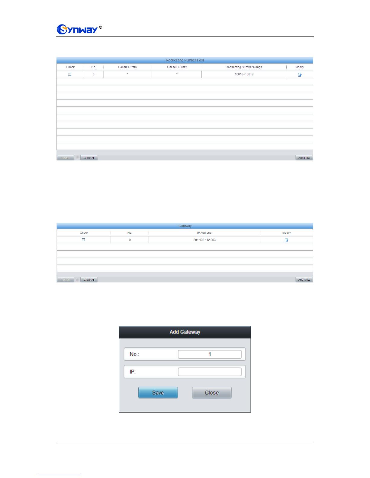
Synway Information Engineering Co., Ltd
SMG Series Digital Gateway User Manual (Version 1.6.0) Page 73
3.6.3 Redirecting Number
Figure 3-73 Redirecting Number Interface
Redirecting Number Pool for ISDN is almost the same as Original CalleeID Pool for SS7; only the
calling/called party number changes from SS7 to ISDN. See Figure 3-73 for Redirecting Number
Pool for ISDN. The configuration items on this interface are the same as those on original
CalleeID pool for SS7 (Figure 3-58).
3.6.4 Add Gateway
Figure 3-74 Add Gateway Interface
See Figure 3-74 for the Add Gateway Interface. A new gateway can be added by the Add New
button on the bottom right corner of the list in the above figure. The information about the added
gateway will be displayed under Operation Info PSTN Status. See Figure 3-75 for the
gateway adding interface.
Figure 3-75 Add New Gateway
The table below explains the items shown in above figures.

Synway Information Engineering Co., Ltd
SMG Series Digital Gateway User Manual (Version 1.6.0) Page 74
Item
Description
No.
The corresponding number for a new gateway, which starts from 0.
IP
The corresponding IP address for the new gateway, which must be in the same
network section of the SIP address set via VoIPSIP.
After configuration, click Save to save the above settings into the gateway or click Close to cancel
the settings.
Click Modify in Figure 3-74 to modify the gateway information. See Figure 3-76 for the gateway
modification interface. The configuration items on this interface are the same as those on the Add
New Gateway interface.
Figure 3-76 Modify Gateway Information

Synway Information Engineering Co., Ltd
SMG Series Digital Gateway User Manual (Version 1.6.0) Page 75
3.7 SS1 Settings
Figure 3-77 SS1 Settings Interface
See Figure 3-77 for the SS1 settings interface. This interface appears only when the configuration
item Signaling Protocol on the PCM settings interface is set to SS1. You can set general
information of SS1. After configuration, click Save to save your settings into the gateway or click
Reset to restore the configurations. If a dialog box pops up after you save your settings asking
you to restart the service, do it immediately to apply the changes. Refer to 3.12.17 Restart for
detailed instructions. The table below explains the items shown in Figure 3-77.
Item
Description
Country
Sets the country to use SS1, with the default value of CHINA.
C/D Value
Sets the value of CD in the ABCD signaling codes sent by the local end to the remote
PBX. The high 6 bits should be set to 0, being reserved; the low 2 bits are C/D
signaling codes, Bit1 (Signaling Code C) and Bit0 (Signaling Code D), both with the
default value of 1.
ABCD Duration
Timeout
Sets the minimum duration of ABCD signaling codes sent out by the remote PBX,
calculated by millisecond (ms), which has to be the multiple of 8, with the default value
of 0. Only when the on-line ABCD signaling codes vary and the new value keeps for
more than the time specified by this configuration item will the gateway confirm the
change of ABCD codes, Otherwise, the driver will believe there are undesired dithering
signals on the line.

Synway Information Engineering Co., Ltd
SMG Series Digital Gateway User Manual (Version 1.6.0) Page 76
Max MFC Waiting
Time
Sets the maximum waiting time, i.e. the timer T2 for the SS1 state machine, calculated
by second, with the default value of 10.
CalleeID Length
for Incoming
Calls
Sets the way to receive the number, with the default value of 3 which means receiving
all the 3 digits of the called party number of the incoming call will put the local number
reception into an end.
KB Setting
Timeout
Sets the maximum time to wait for the application to configure the KB signal, calculated
by second, with the default value of 3.
KD Wait Time
Sets the maximum time to wait for the remote PBX to send the KD signal (i.e. the timer
T3) in the SS1 channel state machine, calculated by second, with the default value of
60.
Delay Time
before Ringing
State
Sets the delay time, i.e. a period of waiting time before the channel goes into the
„Ringing‟ state following the reception of the complete called party number in case the
SS1 channel on the gateway serves as the incoming end. It is calculated by second,
with the default value of 0.
ACK Wait
Timeout
Sets the value of the timer T5, calculated by second, with the default value of 60.
Calling Party’s
Category (KA
Signal)
Sets the KA signal (calling party‟s category at the local end) sent in an outgoing call.
The value range is 1~10, with the default value of 1 (ordinary/regular).
KB Wait Timeout
Sets the maximum time to wait for the KB signal from the remote PBX, calculated by
second, with the default value of 60.
Originating
Service Type (KD
Signal)
Sets the originating service type, i.e. KD, for an outgoing call. The value range is 1~6,
with the default value of 3 (local call).
3.8 Fax Settings
See Figure 3-78 for the Fax Settings interface which is used to modify the special fax
configurations.
Figure 3-78 Fax Settings

Synway Information Engineering Co., Ltd
SMG Series Digital Gateway User Manual (Version 1.6.0) Page 77
3.8.1 Fax
Figure 3-79 Fax Configuration Interface (T.38 Mode)
See Figure 3-79 for the fax configuration interface with all default settings under the T.38 fax mode.
Users can configure the general fax parameters via this interface. After configuration, click Save
to save your settings into the gateway or click Reset to restore the configurations. If a dialog box
pops up after you save your settings asking you to restart the service, do it immediately to apply
the changes. Refer to 3.12.17 Restart for detailed instructions. The table below explains the
configuration items in Figure 3-79.
Item
Description
Fax Mode
The real-time IP fax mode. The optional values are T.38, Pass-through and Disable,
with the default value of T.38. Setting this item to Disable means to disable both
T.38 and Pass-through.
T38 Version
Version of T.38 which is defined by ITU-T. Range of value: 0~3, with the default
value of 0.
T38 Negotiation
Sets the Negotiation mode of T.38, including: Unsupported, Initiate Negotiation as
Fax Sender and Initiate Negotiation as Fax Receiver.
Maximum Fax Rate
Sets the maximum faxing rate for both receiving and transmitting. Range of value:
14400, 9600 and 4800, calculated by bps, with the default value of 9600.
Fax Train Mode
Sets the train mode for T.38 fax. The optional values are transferredTCF and
localTCF, with the default value of transferredTCF.
Error Correction
Mode
Sets the error correction mode for T.38 fax. The optional values are
t38UDPRedundancy (Redundancy Error Correction) and t38UDPFEC (Forward
Error Correction), with the default value of t38UDPRedundancy.
T.30 Ecm
Sets whether to enable the T.30 error correction mode. By default this feature is
enabled.

Synway Information Engineering Co., Ltd
SMG Series Digital Gateway User Manual (Version 1.6.0) Page 78
Min Duration of CNG
As stipulated in the standard FAX CNG, the minimum duration of CNG is 500ms ±
15%, calculated by ms, with the default value of 425.
Note: Usually there is no need to modify it; please contact our technicians if
necessary.
Min Duration of CED
As stipulated in the standard FAX CED, the minimum duration of CED is
2600~4000ms, calculated by ms, with the default value of 2600.
Note: Usually there is no need to modify it; please contact our technicians if
necessary.
If you set Fax Mode to Pass-through, you can see the interface shown as Figure 3-80.
Figure 3-80 Fax Configuration Interface (Pass-through Mode)
The table below explains the configuration item in the above figure.
Item
Description
Pass-through
Payload
RTP Payload under the pass-through fax mode. Range of value: 96~127, with the
default value of 102.
3.9 Route Settings
Route Settings is used to specify the routing rules for calls on two directions: IPPSTN and
PSTNIP. See Figure 3-81.
Figure 3-81 Route Settings
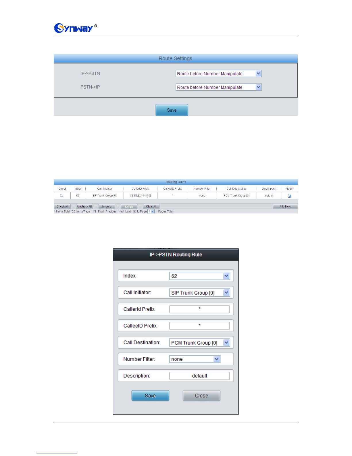
Synway Information Engineering Co., Ltd
SMG Series Digital Gateway User Manual (Version 1.6.0) Page 79
3.9.1 Routing Parameters
Figure 3-82 Routing Parameters Configuration Interface
See Figure 3-82 for the routing parameters configuration interface. On this interface, you can set
the routing rules for calls respectively on two directions IPPSTN and PSTNIP to be routing
before or after number manipulation. The default value is Route before Number Manipulate.
After configuration, click Save to save the above settings into the gateway.
3.9.2 IP to PSTN
Figure 3-83 IPPSTN Routing Rule Configuration Interface
See Figure 3-83 for the IPPSTN routing rule configuration interface. A new routing rule can be
added by the Add New button on the bottom right corner of the list in the above figure. See Figure
3-84 for the IPPSTN routing rule adding interface.

Synway Information Engineering Co., Ltd
SMG Series Digital Gateway User Manual (Version 1.6.0) Page 80
Figure 3-84 Add New Routing Rule (IPPSTN)
The table below explains the items shown in the above figure.
Item
Description
Index
The unique index of each routing rule, which denotes its priority. A routing rule with
a smaller index value has a higher priority. If a call matches several routing rules, it
will be processed according to the one with the highest priority.
Call Initiator
SIP trunk group from where the call is initiated. This item can be set to a specific
SIP trunk group or SIP Trunk Group [ANY] which indicates any SIP trunk group.
CallerID Prefix,
CalleeID Prefix
A string of numbers at the beginning of the calling/called party number. This item
can be set to a specific string or “*” which indicates any string. These two
configuration items together with Call Initiator can specify the calls which apply to a
routing rule.
Note: Multiple rules are supported for CallerID/CalleeID prefix. They are separated
by “:”.
Call Destination
PCM trunk group to which the call will be routed.
Number Filter
Number filter rule which will be applicable to this route. It is set in Number Filter.
See 3.10.4 Filtering Rule for details.
Description
More information about each routing rule.
After configuration, click Save to save the settings into the gateway or click Close to cancel the
settings.
Click Modify in Figure 3-83 to modify a routing rule. See Figure 3-85 for the IPPSTN routing
rule modification interface. The configuration items on this interface are the same as those on the
Add New Routing Rule (IPPSTN) interface. Note that the item Index cannot be modified.
Figure 3-85 Modify Routing Rule (IPPSTN)

Synway Information Engineering Co., Ltd
SMG Series Digital Gateway User Manual (Version 1.6.0) Page 81
To delete a routing rule, check the checkbox before the corresponding index in Figure 3-83 and
click the Delete button. Check All means to select all available items on the current page;
Uncheck All means to cancel all selections on the current page; Inverse means to uncheck the
selected items and check the unselected. To clear all routing rules at a time, click the Clear All
button in Figure 3-83.
3.9.3 PSTN to IP
Figure 3-86 PSTNIP Routing Rule Configuration Interface
See Figure 3-86 for the PSTNIP routing rule configuration interface. A new routing rule can be
added by the Add New button on the bottom right corner of the list in the above figure. See Figure
3-87 for the PSTNIP routing rule adding interface.
Figure 3-87 Add New Routing Rule (PSTNIP)
The table below explains the items shown in the above figure.
Item
Description
Index
The unique index of each routing rule, which denotes its priority. A routing rule with
a smaller index value has a higher priority. If a call matches several routing rules, it
will be processed according to the one with the highest priority.
Call Initiator
PCM trunk group from which the call is initiated. This item can be set to a specific
PCM trunk group or PCM Trunk Group [ANY] which indicates any PCM trunk group.
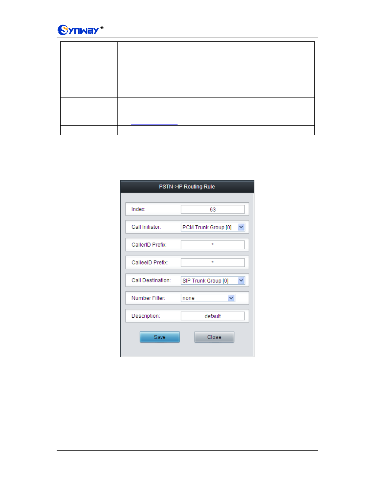
Synway Information Engineering Co., Ltd
SMG Series Digital Gateway User Manual (Version 1.6.0) Page 82
CallerID Prefix,
CalleeID Prefix
A string of numbers at the beginning of the calling/called party number. This item
can be set to a specific string or “*” which indicates any string. These two
configuration items together with Call Initiator can specify the calls which apply to a
routing rule.
Note: Multiple rules are supported in callerID/calleeID prefix. They should be
separated by “:”.
Call Destination
SIP trunk group to which the call will be routed.
Number Filter
Number filter rule which will be applicable to this route. It is set in Number Filter.
See 3.10.4 Filtering Rule for detailed setting.
Description
More information about each routing rule.
After configuration, click Save to save the settings into the gateway or click Close to cancel the
settings.
Click Modify in Figure 3-86 to modify a routing rule. See Figure 3-88 for the PSTNIP routing
rule modification interface. The configuration items on this interface are the same as those on the
Add New Routing Rule (PSTNIP) interface. Note that the item Index cannot be modified.
Figure 3-88 Modify Routing Rule (PSTNIP)
To delete a routing rule, check the checkbox before the corresponding index in Figure 3-86 and
click the Delete button. Check All means to select all available items on the current page;
Uncheck All means to cancel all selections on the current page; Inverse means to uncheck the
selected items and check the unselected. To clear all routing rules at a time, click the Clear All
button in Figure 3-86.
3.10 Number Filter
Number Filter includes four parts: Whitelist, Blacklist, Number Pool and Filtering Rule. See
Figure 3-89.

Synway Information Engineering Co., Ltd
SMG Series Digital Gateway User Manual (Version 1.6.0) Page 83
Figure 3-89 Number Filter Interface
3.10.1 Whitelist
Figure 3-90 Whitelist Setting Interface
See Figure 3-90 for the Whitelist Setting Interface, which includes two parts: CallerID Whitelist
and CalleeID Whitelist.
A new CallerID/CalleeID whitelist can be added by the Add New button. See Figure 3-91, Figure
3-92 for CallerID/CalleeID whitelist adding interface.
Figure 3-91 Add New CallerIDs in Whitelist Interface
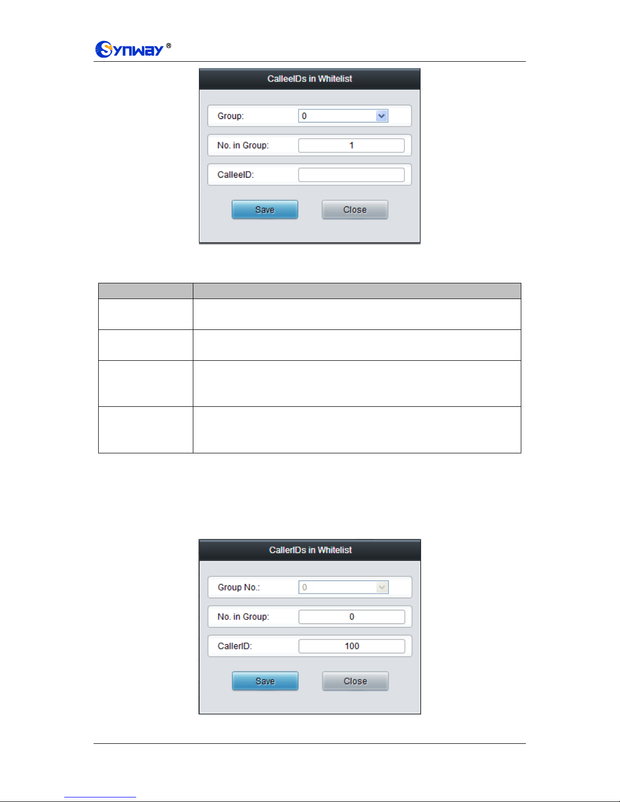
Synway Information Engineering Co., Ltd
SMG Series Digital Gateway User Manual (Version 1.6.0) Page 84
Figure 3-92 Add New CalleeIDs in Whitelist Interface
The table below explains the items shown in above figures.
Item
Description
Group
The corresponding Group ID for CallerIDs/CalleeIDs in the whitelist. The value
range is 0~7.
No. in Group
The corresponding No. for different CallerIDs/CalleeIDs in a same group. It is
allowed to set up to 100 numbers in one group.
CallerID
CallerID in the whitelist, which must be filled in with numbers or “*” (indicating any
string) and can not be left empty. Example: 135*1 denotes any CallerIDs which start
from 135 and end with 1 will be accepted.
CalleeID
CalleeID in the whitelist, which must be filled in with numbers or “*” (indicating any
string) and can not be left empty. Example: 135*1 denotes any CalleeIDs which start
from 135 and end with 1 will be accepted.
After configuration, click Save to save the above settings into the gateway or click Close to cancel
the settings.
Click Modify in Figure 3-90 to modify the CallerID or CalleeID whitelist. See Figure 3-93, Figure
3-94 for CallerIDs/CalleeIDs on the Whitelist Modification interface. The configuration items on
this interface are the same as those on the Add New CallerIDs/CalleeIDs in Whitelist interface.
The item Group No. cannot be modified.
Figure 3-93 Modify CallerIDs in Whitelist

Synway Information Engineering Co., Ltd
SMG Series Digital Gateway User Manual (Version 1.6.0) Page 85
Figure 3-94 Modify CalleeIDs in Whitelist
To delete a CallerIDs/CalleeIDs in the whitelist, check the checkbox before the corresponding
index in Figure 3-90 and click the „Delete‟ button. To clear all CallerIDs/CalleeIDs in the whitelist
at a time, click the Clear All button in Figure 3-90.
Note: If a CallerID or CalleeID set in the whitelist is the same as one in the blacklist, it will go
invalid. That is, the blacklist has a higher priority than the whitelist.
3.10.2 Blacklist
Figure 3-95 Blacklist Setting Interface
The Blacklist Setting interface is almost the same as the Whitelist Setting interface; only the
whitelist changes to the blacklist. See Figure 3-95. The configuration items on this interface are
the same as those on the Whitelist Setting interface (Figure 3-91, Figure 3-92).
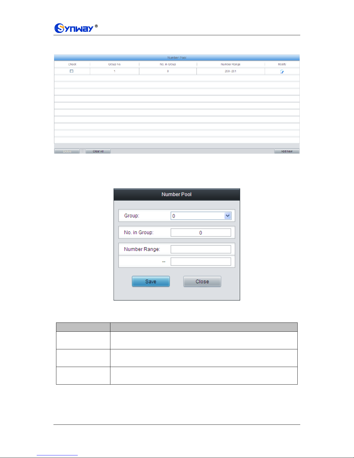
Synway Information Engineering Co., Ltd
SMG Series Digital Gateway User Manual (Version 1.6.0) Page 86
3.10.3 Number Pool
Figure 3-96 Number Pool Setting Interface
See Figure 3-96 for the Number Pool Setting interface. A new number pool can be added by the
Add New button on the bottom right corner of the list in the above figure. See Figure 3-97 for the
Number Pool adding interface.
Figure 3-97 Add New Number Pool
The table below explains the items shown in the above figure.
Item
Description
Group
The corresponding Group ID for numbers in the number pool. The value range is
0~15.
No. in Group
The corresponding No. for different numbers in a same group. It supports up to 100
number s in one group.
Number Range
The range of the numbers in a number Pool. It must be filled in with numbers and
can not be left empty.
After configuration, click Save to save the above settings into the gateway or click Close to cancel
the settings.
Click Modify in Figure 3-96 to modify the number pool. See Figure 3-98 for the number pool
modification interface. The configuration items on this interface are the same as those on the Add
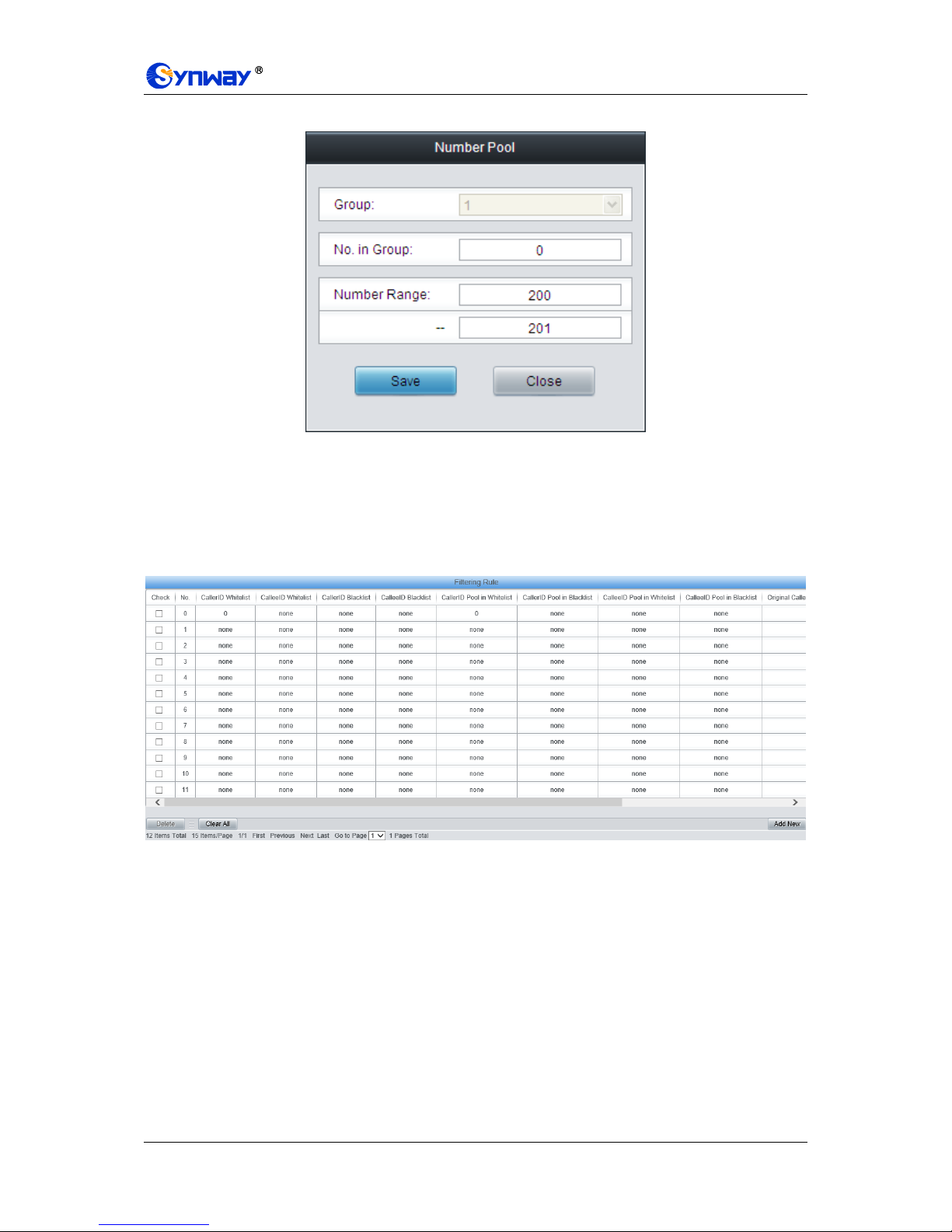
Synway Information Engineering Co., Ltd
SMG Series Digital Gateway User Manual (Version 1.6.0) Page 87
New Number Pool interface.
Figure 3-98 Modify Number Pool Interface
To delete a number pool, check the checkbox before the corresponding index in Figure 3-96 and
click the „Delete‟ button. To clear all number pools at a time, click the Clear All button in Figure
3-96.
3.10.4 Filtering Rule
Figure 3-99 Filtering Rule Setting Interface
See Figure 3-99 for the Filtering Rule Setting Interface. A new filtering rule can be added by the
Add New button on the bottom right corner of the list in the above figure. See Figure 3-100 for the
Filtering Rule Adding interface.
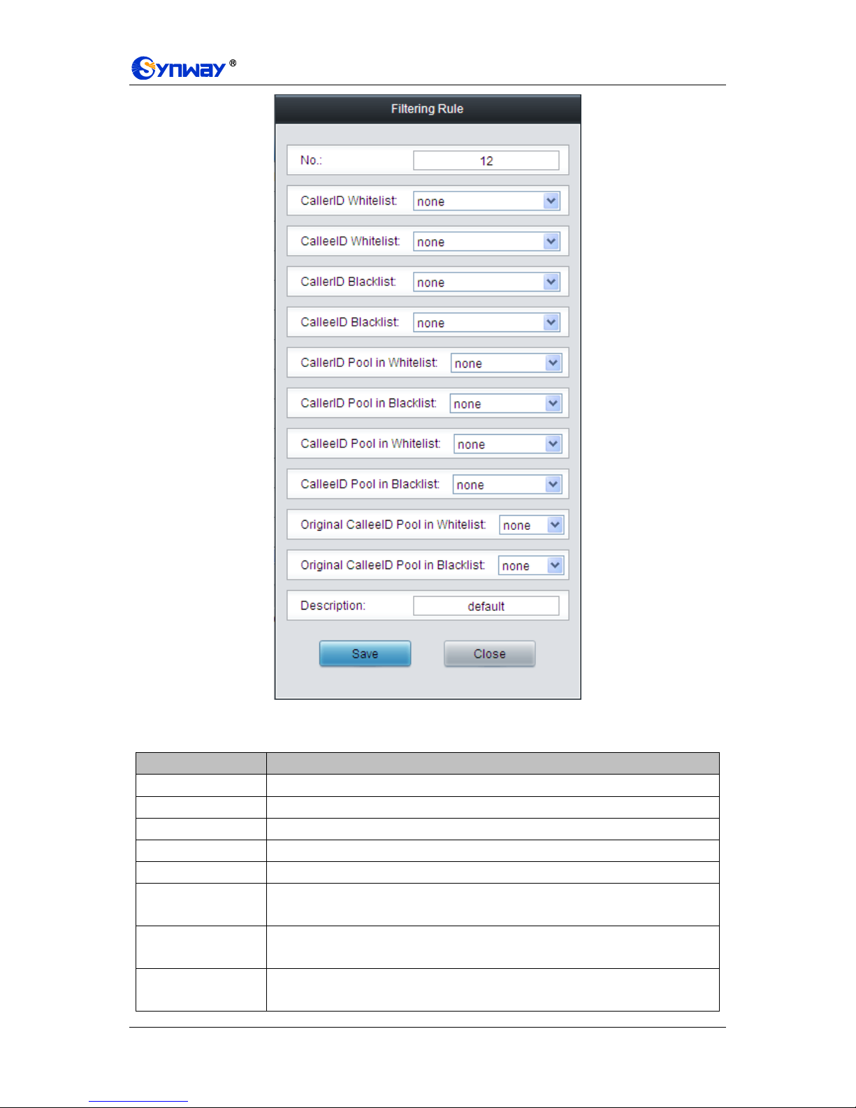
Synway Information Engineering Co., Ltd
SMG Series Digital Gateway User Manual (Version 1.6.0) Page 88
Figure 3-100 Add New Filtering Rule
The table below explains the items shown in the above figure.
Item
Description
No.
The corresponding number for a filtering rule. The value range is 0~99.
CallerID Whitelist
The Group No. of CallerIDs saved on the whitelist setting interface.
CalleeID Whitelist
The Group No. of CalleeIDs saved on the whitelist setting interface.
CallerID Blacklist
The Group No. of CallerIDs saved on the blacklist setting interface.
CalleeID Blacklist
The Group No. of CalleeIDs saved on the blacklist setting interface.
CallerID Pool in
Whitelist
Select a Group No. which is set in the whitelist from the number pool as the CallerID
pool in whitelist.
CallerID Pool in
Blacklist
Select a Group No. which is set in the blacklist from the number pool as the CallerID
pool in blacklist.
CalleeID Pool in
Whitelist
Select a Group No. which is set in the whitelist from the number pool as the CalleeID
pool in whitelist.
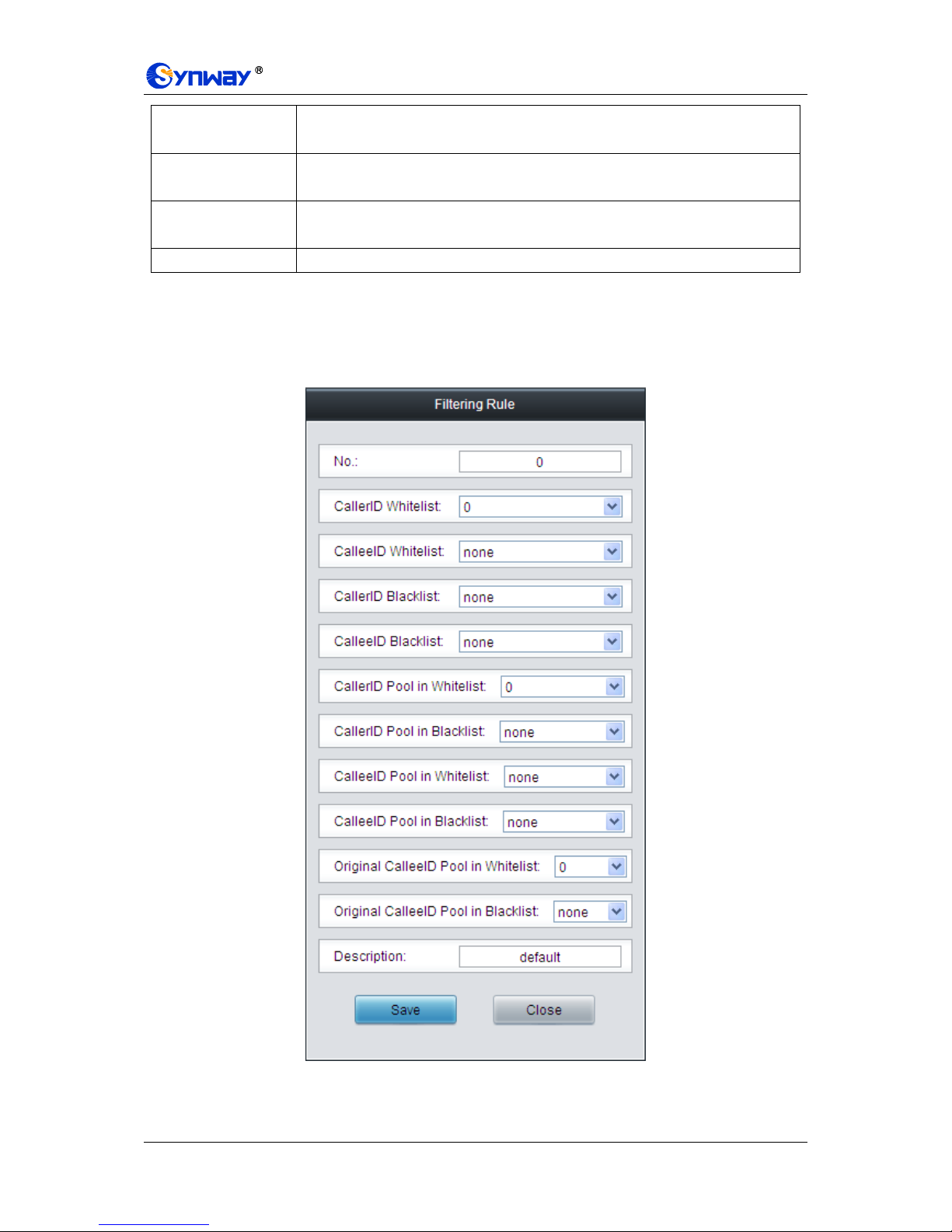
Synway Information Engineering Co., Ltd
SMG Series Digital Gateway User Manual (Version 1.6.0) Page 89
CalleeID Pool in
Blacklist
Select a Group No. which is set in the blacklist from the number pool as the CalleeID
pool in blacklist.
Original CalleeID
Pool in Whitelist
Select a Group No. which is set in the whitelist from the number pool as the original
CalleeID pool in whitelist.
Original CalleeID
Pool in Blacklist
Select a Group No. which is set in the blacklist from the number pool as the original
CalleeID pool in blacklist.
Description
Remarks for the filtering rule. It can be any information, but can not be left empty.
After configuration, click Save to save the above settings into the gateway or click Close to cancel
the settings.
Click Modify in Figure 3-99 to modify the filtering rule. See Figure 3-101 for the filtering rule
modification interface. The configuration items on this interface are the same as those on the Add
New Filtering Rule interface.
Figure 3-101 Modify Filtering Rule Interface
To delete a filtering rule, check the checkbox before the corresponding index in Figure 3-99 and

Synway Information Engineering Co., Ltd
SMG Series Digital Gateway User Manual (Version 1.6.0) Page 90
click the „Delete‟ button. To clear all filtering rules at a time, click the Clear All button in Figure
3-99.
3.11 Number Manipulation
Number Manipulation includes seven parts: IPPSTN CallerID, IPPSTN CalleeID, IPPSTN
Original CalleeID, PSTNIP CallerID, PSTNIP CalleeID, PSTNIP Original CalleeID and
CallerID Pool. See Figure 3-102.
Figure 3-102 Number Manipulation
3.11.1 IP to PSTN CallerID
Figure 3-103 IPPSTN CallerID Manipulation Interface
See Figure 3-103 for the IPPSTN CallerID manipulation interface. A new number manipulation
rule can be added by the Add New button on the bottom right corner of the list in the above figure.
See Figure 3-104 for the IPPSTN CallerID manipulation rule adding interface.
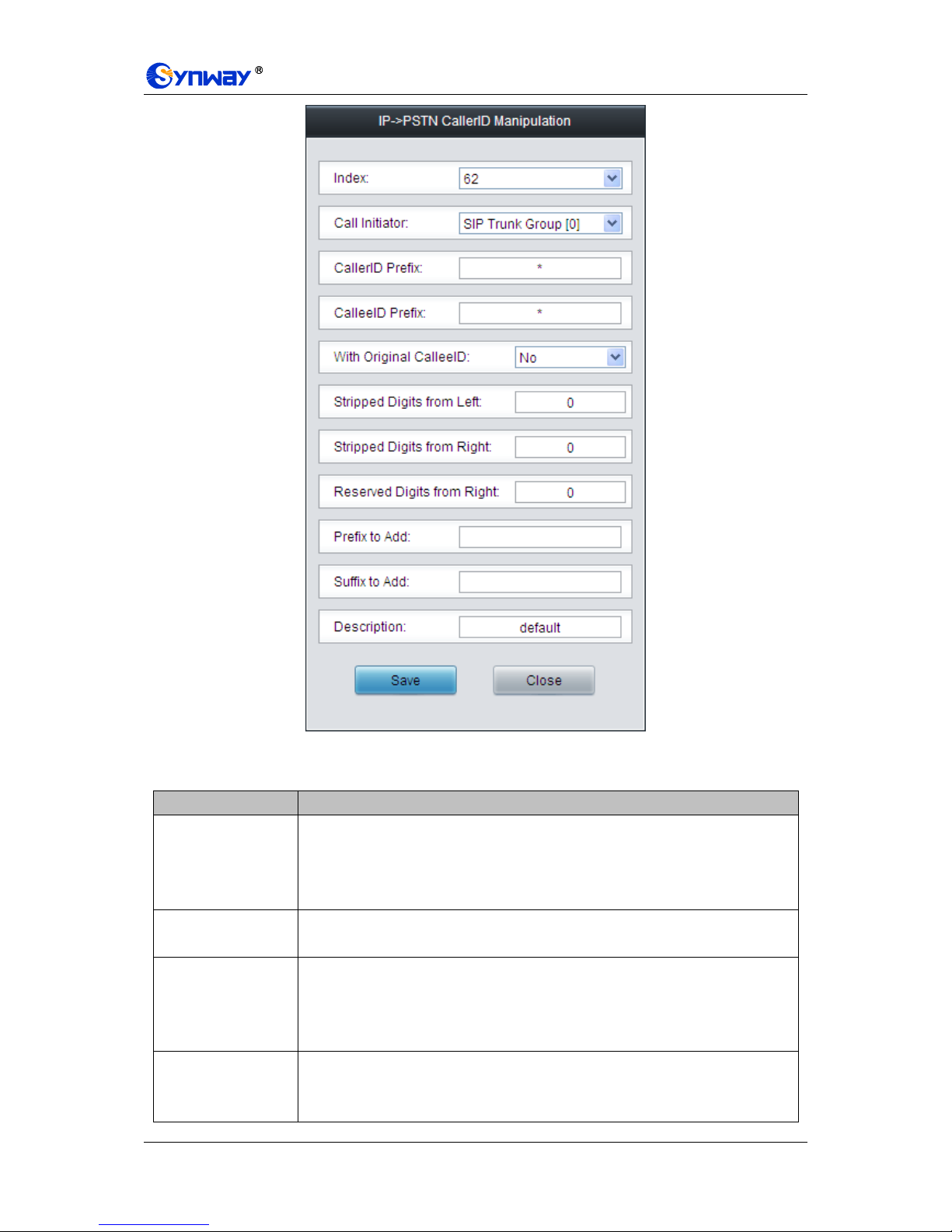
Synway Information Engineering Co., Ltd
SMG Series Digital Gateway User Manual (Version 1.6.0) Page 91
Figure 3-104 Add IPPSTN CallerID Manipulation Rule
The table below explains the items shown in the above figure.
Item
Description
Index
The unique index of each number manipulation rule, which denotes its priority. A
number manipulation rule with a smaller index value has a higher priority. If a call
matches several number manipulation rules, it will be processed according to the
one with the highest priority.
Call Initiator
SIP trunk group from where the call is initiated. This item can be set to a specific
SIP trunk group or SIP Trunk Group[ANY] which indicates any SIP trunk group.
CallerID Prefix,
CalleeID Prefix
A string of numbers at the beginning of the calling/called party number. This item
can be set to a specific string or “*” which indicates any string. These two
configuration items together with Call Initiator and With Original CalleeID can
specify the calls which apply to a number manipulation rule.
With Original
CalleeID
If this item is set to Yes, it indicates that the number manipulation rule is only
applicable to the calls with original CalleeID/redirecting number. The default value is
No.

Synway Information Engineering Co., Ltd
SMG Series Digital Gateway User Manual (Version 1.6.0) Page 92
Stripped Digits from
Left
The amount of digits to be deleted from the left end of the number. If the value of
this item exceeds the length of the current number, the whole number will be
deleted.
Stripped Digits from
Right
The amount of digits to be deleted from the right end of the number. If the value of
this item exceeds the length of the current number, the whole number will be
deleted.
Reserved Digits
from Right
The amount of digits to be reserved from the right end of the number. Only when the
value of this item is less than the length of the current number will some digits be
deleted from left; otherwise, the number will not be manipulated.
Prefix to Add
Designated information to be added to the left end of the current number.
Suffix to Add
Designated information to be added to the right end of the current number.
Description
More information about each number manipulation rule.
Note: The number manipulation is performed in 5 steps by the order of the following
configuration items: Stripped Digits from Left, Stripped Digits from Right, Reserved Digits
from Right, Prefix to Add and Suffix to Add.
After configuration, click Save to save the settings into the gateway or click Close to cancel the
settings.
Click Modify in Figure 3-103 to modify a number manipulation rule. See Figure 3-105 for the
IPPSTN CallerID manipulation rule modification interface. The configuration items on this
interface are the same as those on the Add IPPSTN CallerID Manipulation Rule interface.
Note that the item Index cannot be modified.

Synway Information Engineering Co., Ltd
SMG Series Digital Gateway User Manual (Version 1.6.0) Page 93
Figure 3-105 Modify IPPSTN CallerID Manipulation Rule
To delete a number manipulation rule, check the checkbox before the corresponding index in
Figure 3-103 and click the Delete button. Check All means to select all available items on the
current page; Uncheck All means to cancel all selections on the current page; Inverse means to
uncheck the selected items and check the unselected. To clear all number manipulation rules at a
time, click the Clear All button in Figure 3-103.
3.11.2 IP to PSTN CalleeID
The number manipulation process for IPPSTN CalleeID is almost the same as that for
IPPSTN CallerID; only the number to be manipulated changes from CallerID to CalleeID. See
Figure 3-106 for IPPSTN CalleeID manipulation interface. The configuration items on this
interface are the same as those on IPPSTN CallerID Manipulation Interface (Figure 3-103).
Figure 3-106 IPPSTN CalleeID Manipulation Interface

Synway Information Engineering Co., Ltd
SMG Series Digital Gateway User Manual (Version 1.6.0) Page 94
3.11.3 IP to PSTN Original CalleeID
The number manipulation process for IPPSTN Original CalleeID is almost the same as that for
IPPSTN CallerID; only the number to be manipulated changes from CallerID to Original
CalleeID. See Figure 3-107 for IPPSTN Original CalleeID manipulation interface. The
configuration items on this interface are the same as those on IPPSTN CallerID Manipulation
Interface (Figure 3-103).
Figure 3-107 IPPSTN Original CalleeID Manipulation Interface
3.11.4 PSTN to IP CallerID
Figure 3-108 PSTNIP CallerID Manipulation Interface
See Figure 3-108 for the PSTNIP CallerID manipulation interface. A new number manipulation
rule can be added by the Add New button on the bottom right corner of the list in the above figure.
See Figure 3-109 for the PSTNIP CallerID manipulation rule adding interface.
 Loading...