

Page 1
Synway AST Series
FXM32
Analog Voice Board
Version 1.0
Synway Information Engineering Co., Ltd
www.synway.net
Page 2

Synway Information Engineering Co., Ltd
Contents
Contents..................................................................................................................... i
Copyright Declaration.............................................................................................. ii
User Guide ............................................................................................................... iii
Revision History ...................................................................................................... iv
Chapter 1 Overview.................................................................................................. 1
1.1 Features........................................................................................................... 1
1.2 Operation Principle .......................................................................................... 3
Chapter 2 Installation............................................................................................... 4
2.1 Hardware Structure.......................................................................................... 4
2.1.1 Motherboard............................................................................................... 5
2.1.2 Daughterboard............................................................................................ 6
2.1.3 Backboard .................................................................................................. 6
2.1.4 Module........................................................................................................ 6
2.2 Interface Identification...................................................................................... 7
2.3 Channel Number Identification......................................................................... 9
2.4 System Requirements.....................................................................................11
2.5 Hardware Installation......................................................................................11
Appendix A Technical Specifications ................................................................... 14
Appendix B Technical/Sales Support ................................................................... 15
Synway FXM32 Analog Voice Board Hardware Manual (Version 1.0) Page i
Page 3

Synway Information Engineering Co., Ltd
Copyright Declaration
This manual is provided by Synway Information Engineering Co., Ltd (hereinafter referred to as
‘Synway’) as the support file for ‘Synway FXM Series board driver software’. Both the software and
this manual are copyrighted and protected by the laws of the People's Republic of China.
All rights reserved; no part of this manual may be extracted, modified, copied, reproduced or
transmitted in any form or by any means, electronic or mechanical, without prior written permission
from Synway. By using this manual, you agree to the following Software License Agreement.
Synway reserves the right to revise this manual without prior note. Please contact Synway for the
latest version of this manual before placing an order.
Synway has made every effort to ensure the accuracy of this manual but does not guarantee the
absence of errors. Moreover, Synway assumes no responsibility in obtaining permission and
authorization of any third party patent, copyright or product involved in relation to the use of this
manual.
Note: Asterisk and Digium mentioned in this book are registered trademarks of Digium Inc.
Trixbox is a registered trademark of Fonality. FreeSwitch is a registered trademark of
FreeSwitch.org.
Synway FXM32 Analog Voice Board Hardware Manual (Version 1.0) Page ii
Page 4

Synway Information Engineering Co., Ltd
User Guide
FXM32 has a six-year guarantee. Synway provides you with a good quality after-sales service at
any time under warranty. And what’s more, we give a promise of the three-month
no-questions-asked return policy. Please read Appendix B
to get our contact information.
When you find anything wrong with the board and turn to us for help, please supply your system
log and give necessary assistance to our technicians for a quick diagnosis of the problem.
Synway FXM32 Analog Voice Board Hardware Manual (Version 1.0) Page iii
Page 5
Synway Information Engineering Co., Ltd
Revision History
Version Date Comments
Version 1.0 2009-4 Initial publication
Note: Only major revisions to this manual itself recorded herein.
Synway FXM32 Analog Voice Board Hardware Manual (Version 1.0) Page iv
Page 6
Synway Information Engineering Co., Ltd
Chapter 1 Overview
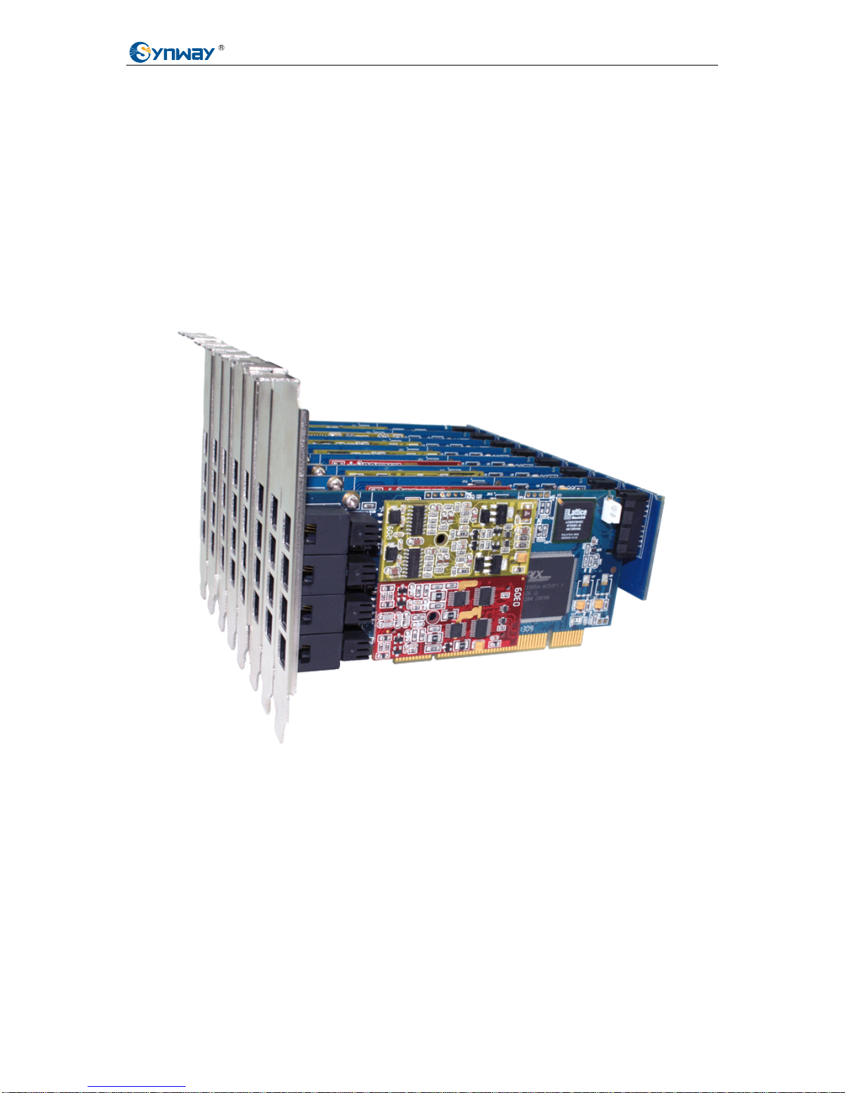
FXM32 is designed with a smart appearance and a flexible structure. The voice quality it provides
is rather splendid. The echo canceller which we developed out independently to cancel echoes in
hardware supports 128ms for time delay estimation. With the extendable daughterboards and the
selectable modules, you can customize systems to what you want. The 2U height and the
half-length design it has minimize the space to install in a chassis so that most common main
frames you find in daily life are big enough to hold it. In a word, this product is really cost effective.
Figure 1-1 below shows the overall structure of FXM32.
Figure 1-1 Overall Structure of FXM32
Note: When installing motherboards and daughterboards, there will be no difference to put
whichever one in front. They can be inserted into any slot on the backboard. See Figure 2-1.
1.1 Features
z Echo Cancellation
1) Compliant with G.168-2002.
2) The basic motherboard supports 256 point (32ms) for time delay estimation on each
Synway FXM32 Analog Voice Board Hardware Manual (Version 1.0) Page 1
Page 7

Synway Information Engineering Co., Ltd
channel while the enhanced motherboard supports 1024 point (128ms).
3) Uses the DSPs on the motherboard to process echoes, not wasting any host resources.
4) Not only cancels out the effect of voice playback on DTMF and busy tones detection, but
also avoids self-excited oscillation and howling, minimizes the possibility of registering
wrong DTMF and busy tones in a conference call, especially suitable for VoIP application
environments.
z DMA
Uses the DMA technique for data reading and writing, greatly minimizing the cost of host CPU.
z Structure
1) Assembles piecemeal just like piling up building blocks. A motherboard offers 4 channels
and you may use the backboard to extend with up to 7 daughterboards. Then 32
channels are available in total. Although these daughterboards take some space, they
can work without the need of PCI/PCIe slots.
2) Several kinds of modules are optional for you to install with the mother/daughter boards
to achieve different purposes. Actually, we provide FXS, FXO and FXC (a compound
body of FXS and FXO). FXC has the capability to ensure safe communication even when
the PC is powered off, which eliminates the damage caused by sudden power cuts.
3) The 2U height and the half-length de sign (Height: 55mm, Length: 120mm) minimize the
space it needs for installation, allowing a great many choices of mainboards and main
frames.
4) You are allowed to fix the module by bolt and the backboard by ouch onto the
mother/daughter board to prevent them from loosening or disengaging during
transportation or in removal.
z Compatibility in Software and Hardware
1) Compatible with all commercial and home mainboards.
2) Includes PCI 2.2 bus with burst data transmission rate up to 132 MB/s; PNP (plug and
play) feature eliminates the need for jumper leads; general PCI design supports 3.3V/5V
PCI slot and PCI-X slot.
Includes PCI Express 1.0a bus with the single-way transmission rate up to 2.5Gb;
supports PCI Express X1, X2, X4, X8, X16 slots.
3) Supports Unix, Linux and Solaris.
4) This board driver is compatible with Zaptel. So it supports a lot of open source PBX
systems, like Asterisk, Trixbox, Yate, CallWeaver, FreeSwitch, etc.
z Interface
The on-board RJ11 jack can connect directly to telepho ne lines, making connection easy and
Synway FXM32 Analog Voice Board Hardware Manual (Version 1.0) Page 2
Page 8
Synway Information Engineering Co., Ltd
malfunctions rare.
z Power
The power for motherboard is supplied by PCI/PCIe slot, while that for backboard and
daughterboard is supplied by host-computer power.
z Indicator
Rear projection indicators. We make use of the gaps between RJ11 jacks and the
light-admitting quality of the jack to hide the indicators behind the RJ11 jacks. Such design not
only ensures the neatness of the board, but also allows you to get the module type and errors
in running without opening the main frame.
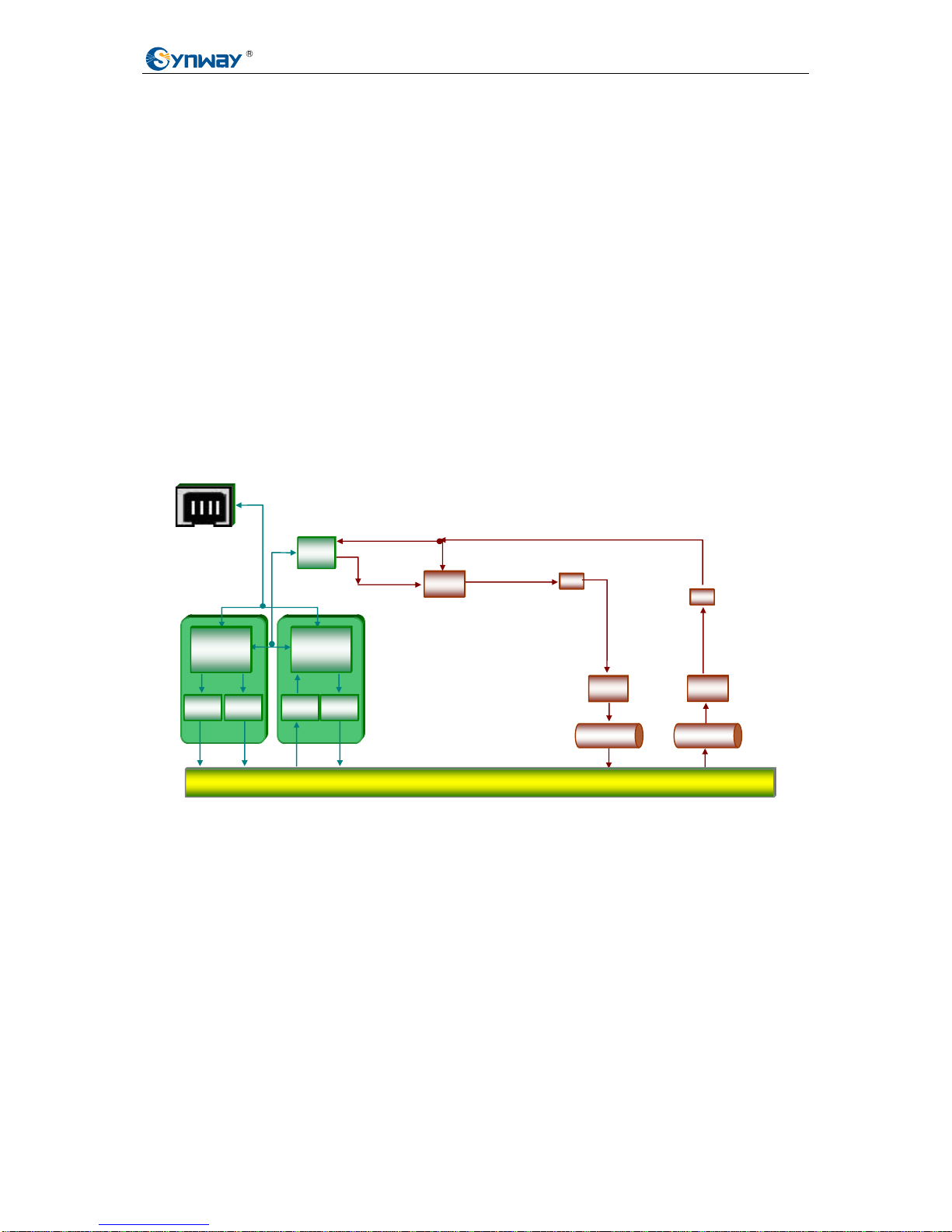
1.2 Operation Principle
Figure 1-2 FXM32 Operation Principle
Inbound Voice
Trunk Board Subscriber
Mother Board
AG
Decoder Encoder
Subscriber
Line
Interface
Circuit
Voltage
Detector
Ring
Detector
Ring
Control
Hook
Detector
Echo
Canceler
Outbound Voice
Phone Interfac
e
CODEC
Recording
Buffer
Playback
Buffer
AG
Subscriber
Line
Interface
Circuit
Host Computer Interface (PCI /PCIe)
Synway FXM32 Analog Voice Board Hardware Manual (Version 1.0) Page 3
Page 9
Synway Information Engineering Co., Ltd
Chapter 2 Installation
2.1 Hardware Structure
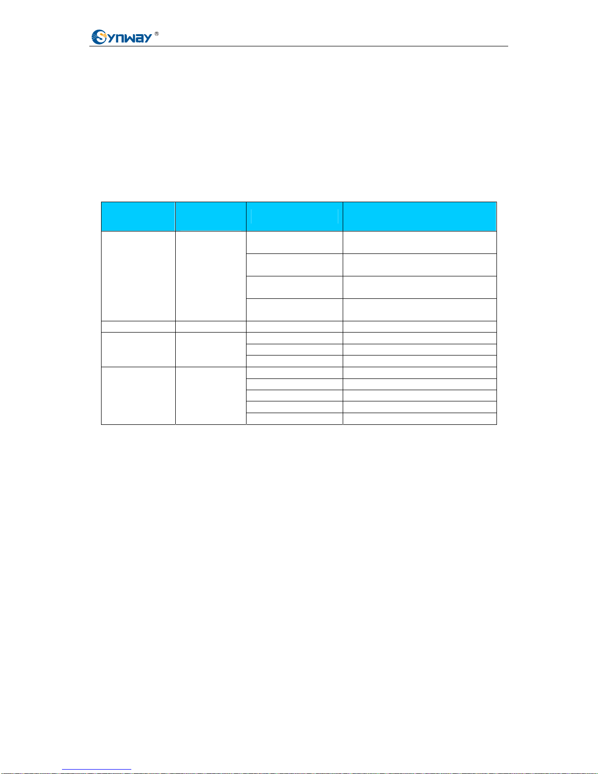
See Table 2-1 below for available models of FXM32 motherboard, daughterboard, module and
backboard.
Component
Maximum
Quantity
Model Comments
FXM3200P
Half-length basic motherboard
with PCI bus
FXM3201P
Half-length enhanced
motherboard with PCI bus
FXM3200E
Half-length basic motherboard
with PCIe bus
Motherboard 1
FXM3201E
Half-length enhanced
motherboard with PCIe bus
Daughterboard 7 FXD400 Half-length daughterboard
FXO200 Trunk module
FXS200 Station module
Module 16
FXC200 Composite module
BP200 Offers 2 slots
BP300 Offers 3 slots
BP400 Offers 4 slots
BP600 Offers 6 slots
Backboard 1
BP800 Offers 8 slots
Table 2-1 Model list for FXM32 Motherboard, Daughterboard, Module and Backboard
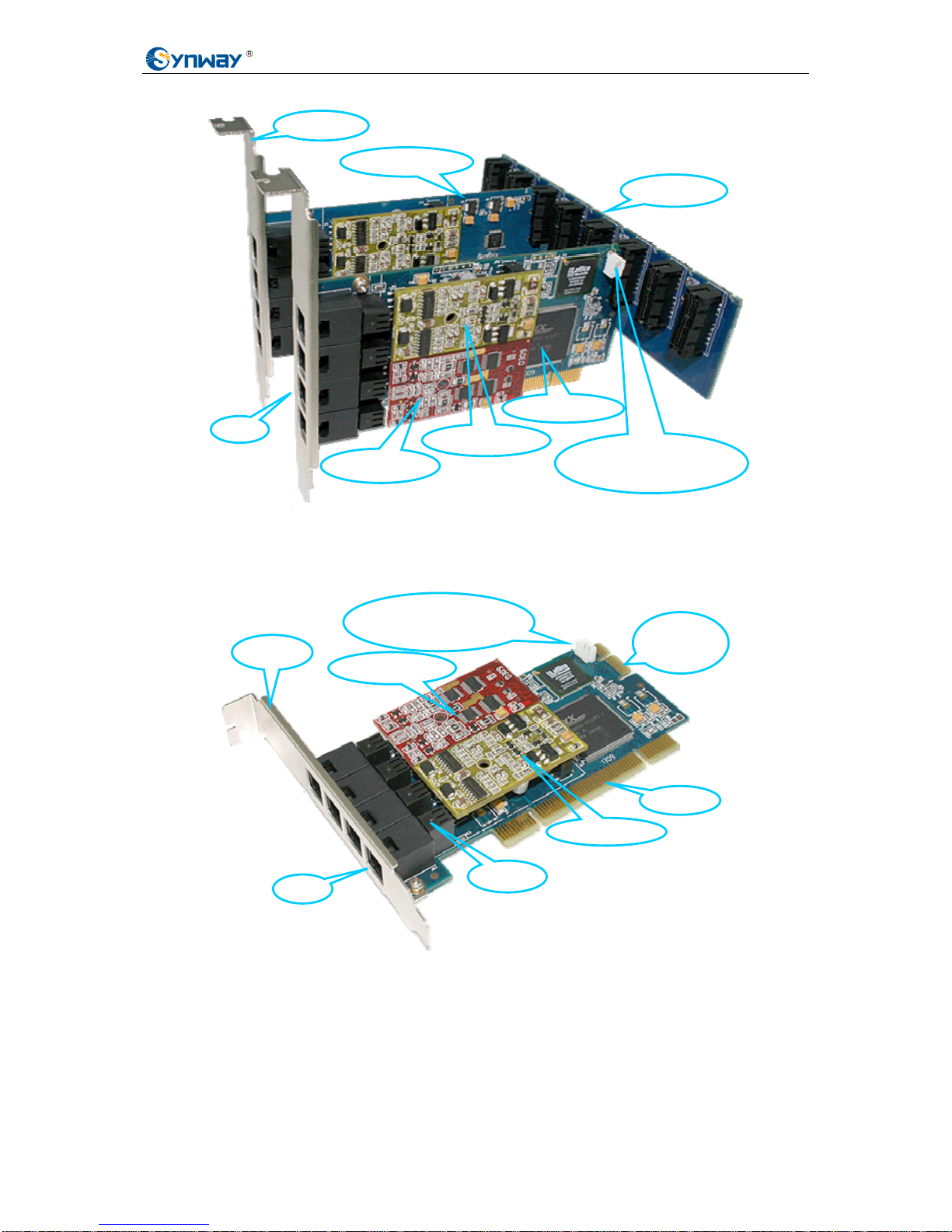
What the following Figure 2-1 illustrates is composed of an FXM3201P motherboard, an FXD400
daughterboard, a BP800 backboard, an FXO200 trunk module and an FXS200 station module.
Synway FXM32 Analog Voice Board Hardware Manual (Version 1.0) Page 4
Page 10
Synway Information Engineering Co., Ltd
Backboard
Motherboard
Figure 2-1 Overall Structure
2.1.1 Motherboard
Trunk Module
Daughterboard
RJ11
L-bracket
Station Module
Clock Synchronization
Line Interface
Trunk Module
PCI Slot
Indicator
RJ11
L-bracket
Station Module
36-pin
Interface
Clock Synchronization
Line Interface
Figure 2-2 FXM3201P Motherboard
Synway FXM32 Analog Voice Board Hardware Manual (Version 1.0) Page 5
Page 11
Synway Information Engineering Co., Ltd
2.1.2 Daughterboard .1.2 Daughterboard
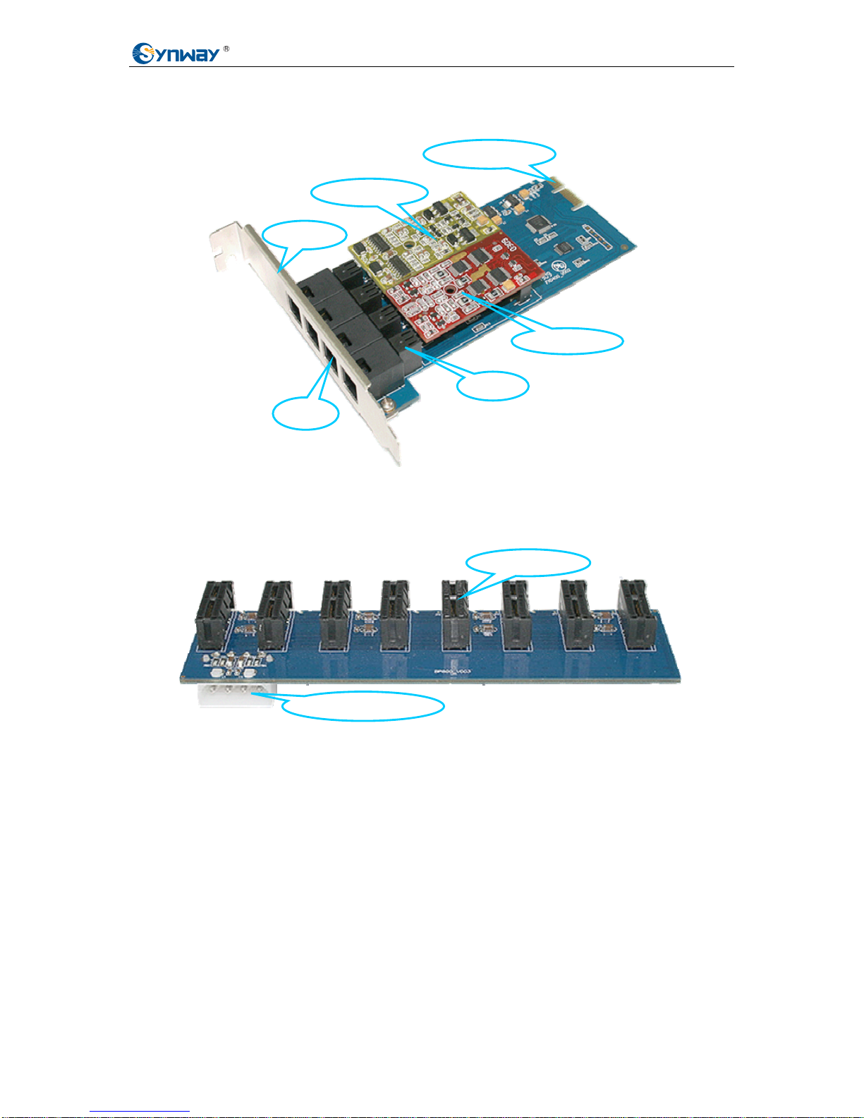
Figure 2-3 FXD400 Daughterboard Figure 2-3 FXD400 Daughterboard
2.1.3 Backboard 2.1.3 Backboard
HD Power Connecto
r
36-pin Slot
Trunk Module
RJ11
L-bracket
Station Module
Indicator
36-pin Interface
Figure 2-4 BP800 Backboard Figure 2-4 BP800 Backboard
2.1.4 Module 2.1.4 Module
The FXM32 can have FXO, FXS or FXC (composite module) only, or be equipped with two or
three of them at the same time.
The FXM32 can have FXO, FXS or FXC (composite module) only, or be equipped with two or
three of them at the same time.
z FXO (Trunk Module) z FXO (Trunk Module)
This module is equipped with the lightning-proof circuit that reaches the telecom standard, and
connects its corresponding channel directly to local lines from Central Office Terminal (COT), with
the abilities to detect line voltage, diagnose line failure, and judge the on-hook/off-hook state of the
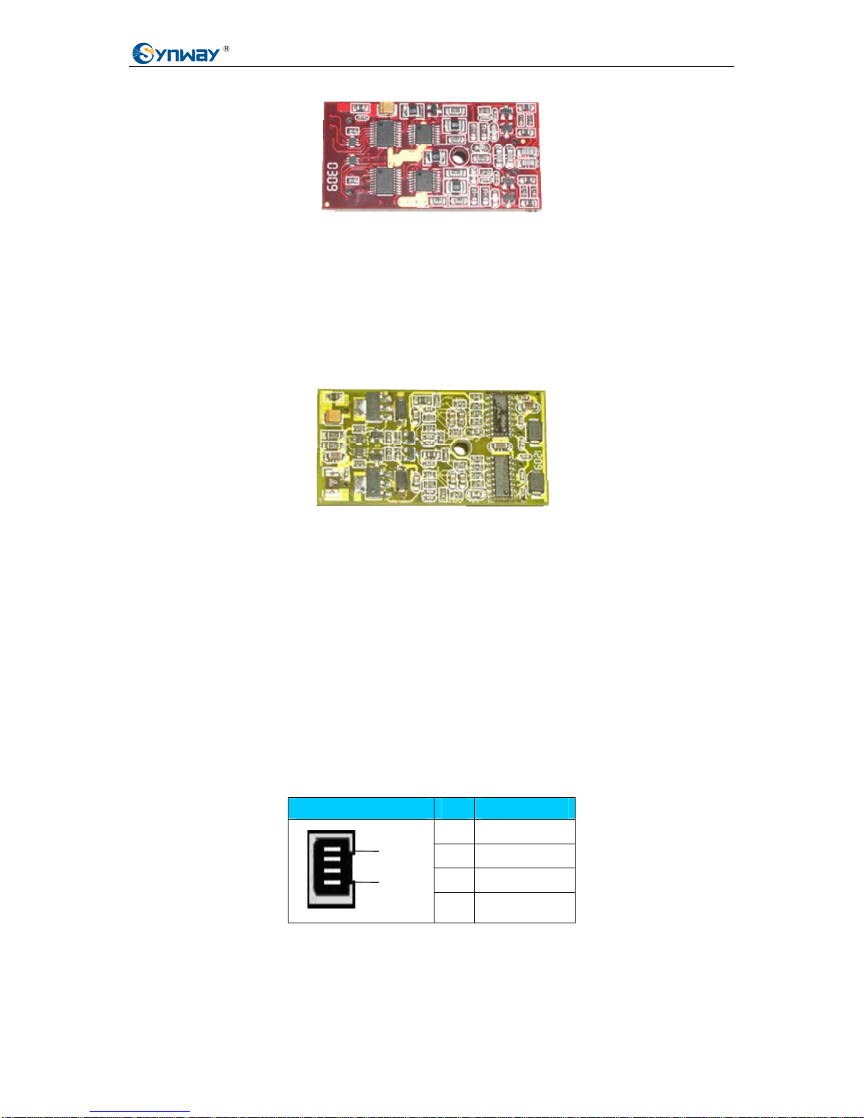
station phone which is linked with it. See Figure 2-5 for its hardware structure.
This module is equipped with the lightning-proof circuit that reaches the telecom standard, and
connects its corresponding channel directly to local lines from Central Office Terminal (COT), with
the abilities to detect line voltage, diagnose line failure, and judge the on-hook/off-hook state of the
station phone which is linked with it. See Figure 2-5 for its hardware structure.
Synway FXM32 Analog Voice Board Hardware Manual (Version 1.0) Page 6
Page 12
Synway Information Engineering Co., Ltd
Figure 2-5 Trunk Module
z FXS (Station Module)
This module functions either as a station phone provided it links directly to a telephone or as an
extension phone for the PBX, supporting delivery of the calling party information in FSK/DTMF to
the phone. It uses -48V standard battery feed voltage and the integrated overcurrent/overvoltage
circuit protection system, can accommodate a subscriber line in length of up to 5.5km. Refer to
Figure 2-6 for its hardware structure.
Figure 2-6 Station Module
z FXC (Composite Module)
A composite module accommodates a trunk channel and a station channel. It has a special
capability of ensuring safe communication via an automatic direct connection of the trunk and
station channels when the driver is not running or the PC is powered off.
2.2 Interface Identification
Each mother/daughter board has 4 RJ11 jacks on the bracket and each jack connects with a
dual-channel module. That is, an FXM32 set can provide 2~32 RJ11 jacks for use.
The pin layout of the 4-pin RJ11 jack is shown as follows.
Pin Note
1
2 Tip
3 Ring
4
Pin1
Pin4
Table 2-2 RJ11
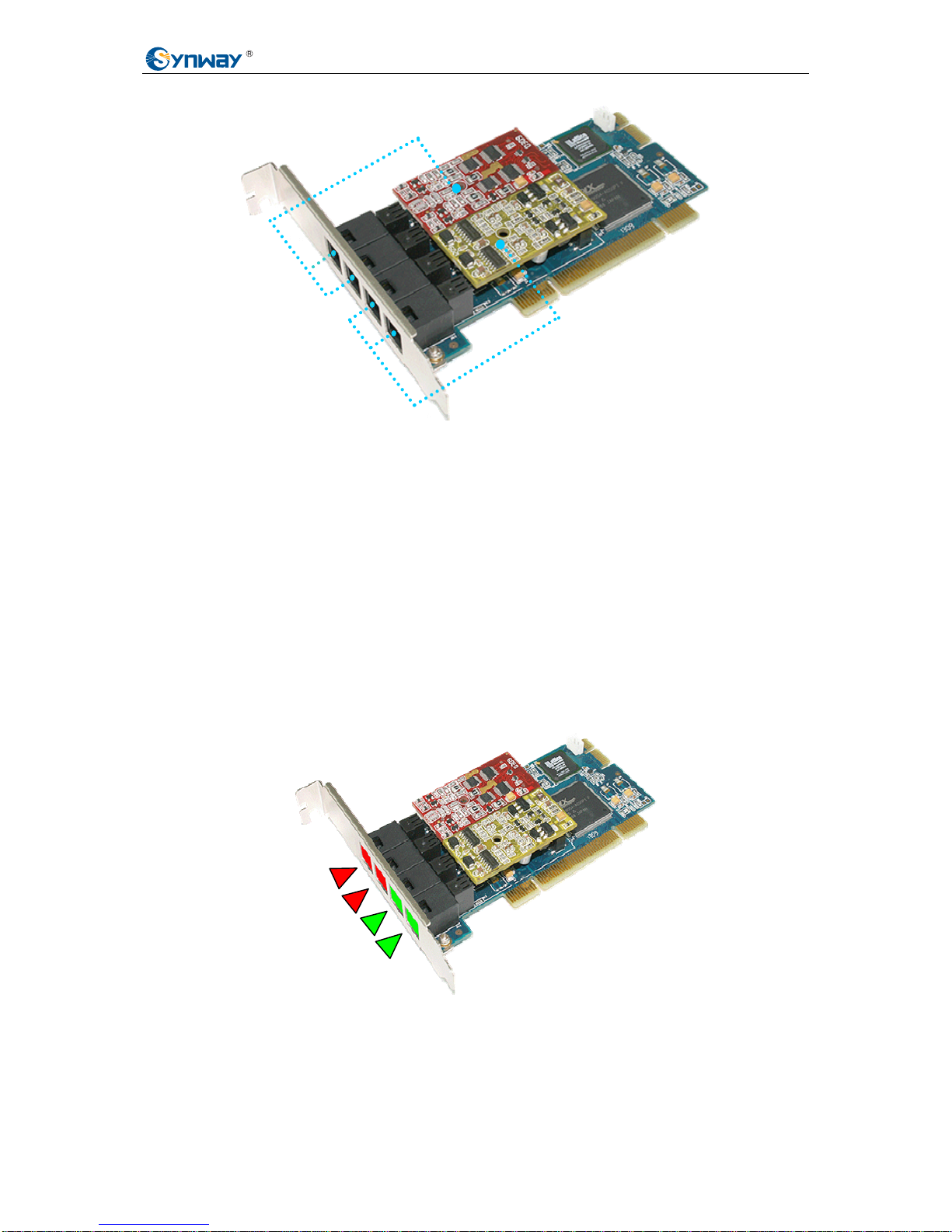
Figure 2-7 below shows the corresponding relationship between the modules on the motherboard
and the RJ11 jacks.
Synway FXM32 Analog Voice Board Hardware Manual (Version 1.0) Page 7
Page 13
Synway Information Engineering Co., Ltd
Figure 2-7 Modules and RJ11 Jacks
Note:
1) What each RJ11 jack corresponds to is the module position but not the module type. For
example, as shown in Figure 2-7 above, Port 1 and Port 2 are connected to Module 1, no
matter Module 1 is FXO, FXS or FXC. Likewise, Port 3 and Port 4 correspond to Module
2.
2) Interfaces and modules for daughterboards are the same as those on the motherboard.
3) When an FXM32 board is running, the indicators at the RJ11 jacks corresponding to trunk
channels stay red, and those at the RJ11 jacks corresponding to station channels stay
green. The indicators being unused will not light up. Take the board in Figure 2-7 for
example, the color of indicators at each interface are as shown in Figure 2-8 below.
Port1
Port2
Port3
Port4
模块 1
模块 2
Figure 2-8 Color of Indicators
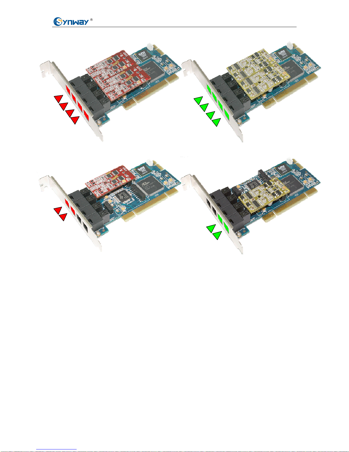
Illustrations (a), (b), (c) and (d) in Figure 2-9 below respectively show how the indicators at RJ11
jacks work with different kind of modules (FXO, FXS or FXC) or with different number of modules
on the board.
Synway FXM32 Analog Voice Board Hardware Manual (Version 1.0) Page 8
Page 14
Synway Information Engineering Co., Ltd
(a) 4 RJ11 Jacks All Correspond to Trunk Channels
(c) 2 RJ11 Jacks Correspond to Trunk Channels
(b) 4 RJ11 Jacks All Correspond to Station Channels
(d) 2 RJ11 Jacks Correspond to Station Channels
Figure 2-9 Indicators at RJ11 Jacks
2.3 Channel Number Identification
An FXM32 set provides up to 32 channels, each of which has a fixed number.
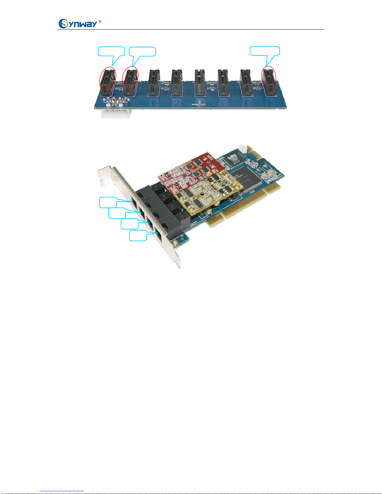
The channel number is only decided by ‘the slot position on the backboard’ and ‘the port
position on the mother/daughter board’. See Figure 2-10 below. The slots on the backboard are
numbered 1~8 from left to right. Then see the following Figure 2-11. The on-board channels are
numbered 1~4 from top to bottom.
Synway FXM32 Analog Voice Board Hardware Manual (Version 1.0) Page 9
Page 15
Synway Information Engineering Co., Ltd
Slot 8
…… ……
Slot 1
Slot 2
Figure 2-10 Slot Number on Backboard
CH1
CH2
CH3
CH4
Figure 2-11 Channel Number on Mother/Daughter Board
When the mother/daughter board is fitted to the backboard, the channels on the board which is
inserted to Slot 1 on the backboard are numbered CH1~CH4, and those on the board which
is inserted to Slot 2 on the backboard are numbered CH5~CH8. Then in turn, the channels
on the board which is inserted to Slot 8 on the backboard are numbered CH29~CH32.
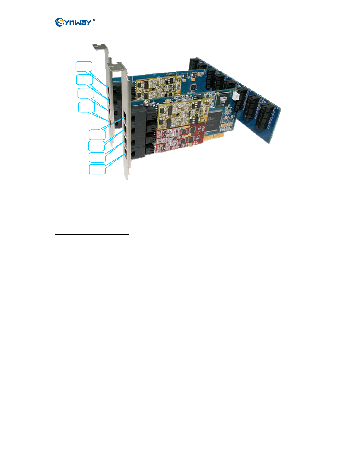
Note: Each position has a fixed channel number. It doesn’t matter where the
mother/daughter board is on the backboard or if there is a board inserted on a slot, just as
shown in Figure 2-12 below.
Synway FXM32 Analog Voice Board Hardware Manual (Version 1.0) Page 10
Page 16
Synway Information Engineering Co., Ltd
CH9
CH10
CH11
CH12
CH21
CH22
CH23
CH24
Figure 2-12 Channel Number Identification
2.4 System Requirements
Host System Requirements
CPU: 300MHz Intel® Pentium®III or above
Memory: 256M or more
HD: Depends on individual requirements
Supported Operating Systems
Linux RH7.2/RH9.0/AS4/FC4/SUSE10
2.5 Hardware Installation
Note: Always turn off the power before installation!
Step 1: Check if all the boards and modules within the package are in good state.
Step 2: Plug all modules you need onto the mother/daughter board.
Follow Figure 2-2 and Figure 2-3 to complete this step.
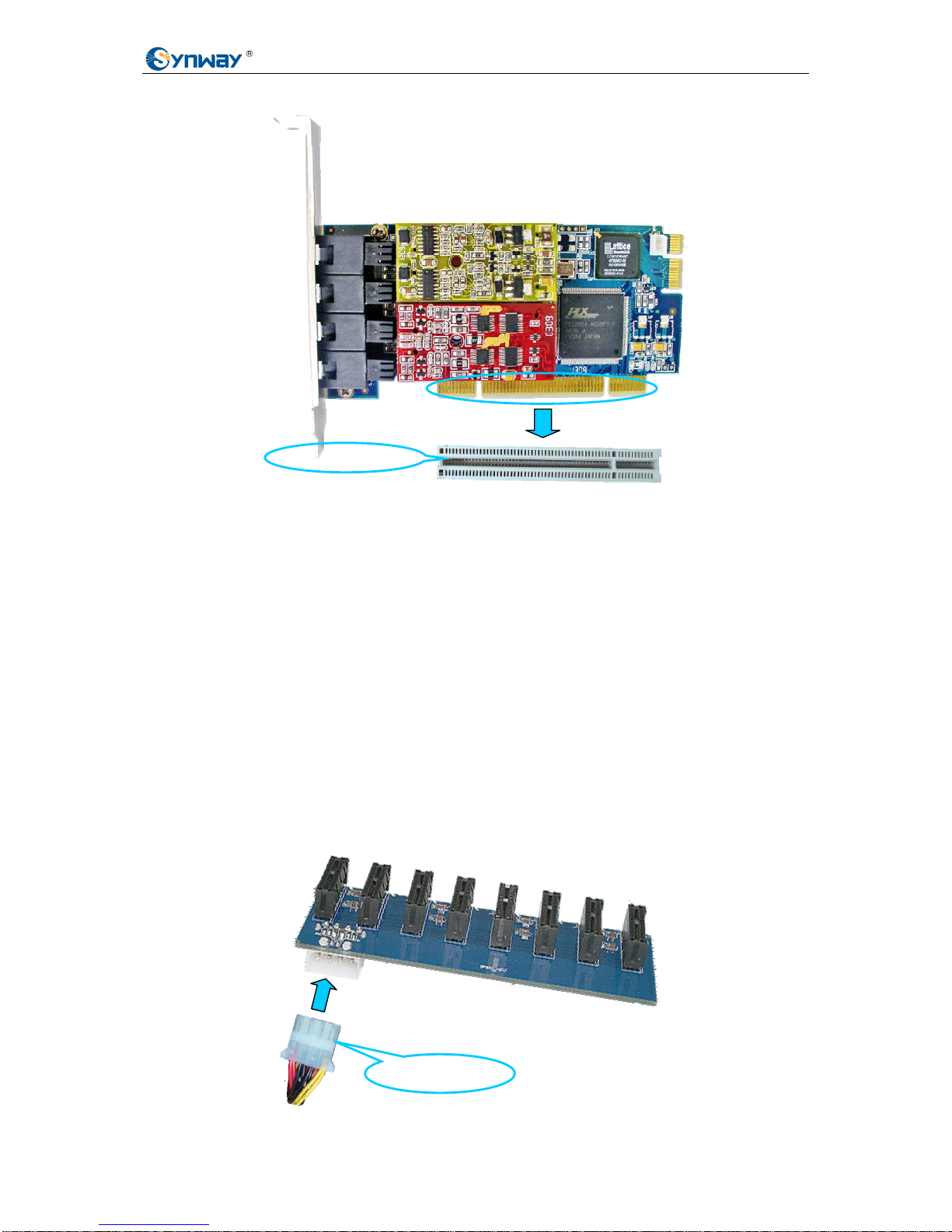
Step 3: Fit the motherboard into the PCI/PCIe slot on the chassis.
Synway FXM32 Analog Voice Board Hardware Manual (Version 1.0) Page 11
Page 17
Synway Information Engineering Co., Ltd
PCI Slot in Chassis
Figure 2-13 Insert Motherboard to PCI/PCIe Slot
Fix the screws on the L-bracket and then go to the next step.
Note: Skip the following Step 4 and Step 5 if you do not use any daughterboard.
Step 4: Fit the daughterboard onto the chassis.
Likewise, fix the screws on the L-bracket and then go to the next step.
Note: Daughterboards need not be inserted into PCI/PCIe slots. And it has no
difference to put whichever one of them in front.
Step 5: Meet the HD power cord to the backboard to connect motherboards with
daughterboards.
Figure 2-14 below shows how to insert the power cord of the chassis to the backboard.
HD Power Plug
Synway FXM32 Analog Voice Board Hardware Manual (Version 1.0) Page 12
Page 18
Synway Information Engineering Co., Ltd
Figure 2-14 Fit HD Power Plug to Backboard
Note:
1) Skip this step if you do not use any daughterboard.
2) You may choose a suit able backboard according to ho w many daughterboards
you need. See Table 2-1 to find the backboard models we supply.
Step 6: Set up an application environment
Connect phone lines with the port to an FXO module and the telephone with the port to an
FXS module, to establish an application environment.
Step 7: Connect the clock synchronization line
Note: Skip this step if there is no need to get clock synchronization for multiple bo ards.
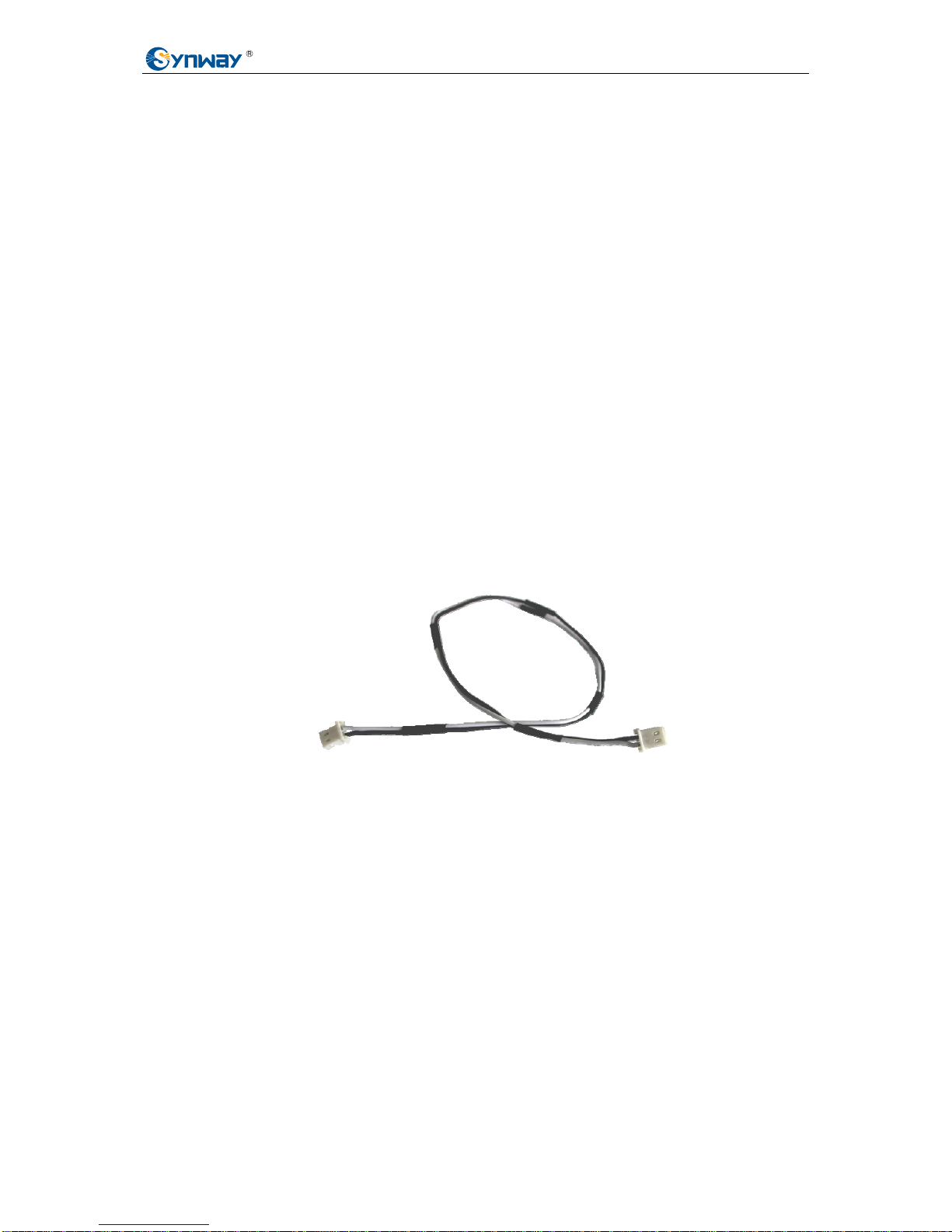
The clock synchronization line is used to connect more than one FXM32 motherboards or
connect FXM32 boards with other kinds of boards (e.g. digital trunk boards) so that these
boards can use a same clock to reduce the errors in faxing and to ensure the accuracy of data
transmission between different boards. (Note: The synchronization of FXM32 motherboards
and daughterboards is achieved by backboards instead of the clock synchronization line.)
See Figure 2-15 below.
Figure 2-15 Clock Synchronization Line
See Figure 2-2 for the clock synchronization line interface on the motherboard.
Step 8: Boot your computer and install the driver
Regarding driver installation, refer to the file ‘SynAST UserManual.doc’ for details.
Synway FXM32 Analog Voice Board Hardware Manual (Version 1.0) Page 13
Page 19

Synway Information Engineering Co., Ltd
Appendix A Technical Specifications
Dimensions
2U height, half-length design
(excluding L-bracket)
Weight
≈385g (excluding modules and external
power supply)
Environment
Operating temperature: 0
℃
—55℃
Storage temperature: -20
℃
—85℃
Humidity: 8%—90% non-condensing
Storage humidity: 8%—90%
non-condensing
Input/output Interface
Telephone line jack: 2~32 4-pin RJ11
Audio Specifications
CODEC: CCITT A/µ-Law 64kbps
Distortion: ≤3%
Frequency response: 300-3400Hz (±3dB)
Signal-to-noise ratio: ≥38dB
Echo suppression: ≥40dB
Maximum System Capacity
Up to 8 boards concurrently per system;
up to 4 channels per board
Power Requirements
Total Power Consumption includes the
electricity use of all motherboards and
daughterboards.
Only motherboards
(with modules fully inserted)
+3.3V DC: 1500mA
(power consumption: 4.95W)
+12V DC: 500mA
(power consumption: 6W)
Only daughterboards
(with modules fully inserted)
+5V DC: 600mA
(power consumption: 3W)
+12V DC: 500mA
(power consumption: 6W)
Impedance
Insulation resistance for PC isolation from
telephone line: ≥2MΩ/500V DC
Telephone line impedance:
Compliant with the national standard
impedance for three-component network
Audio Encoding & Decoding
A-Law 64kbps
μ-Law 64kbps
Sampling Rate
8kHz
Safety
Lightning resistance: Level 4
Synway FXM32 Analog Voice Board Hardware Manual (Version 1.0) Page 14
Page 20

Synway Information Engineering Co., Ltd
Appendix B Technical/Sales Support
Thank you for choosing Synway. Please contact us should you have any inquiry
regarding our products. We shall do our best to help you. However, our technicians
and salesmen are mainly responsible for maintaining our boards and providing
relative technical support. If there are problems about Asterisk, please keep touch
with Digium Inc. for help.
Headquarters
Synway Information Engineering Co., Ltd
http://www.synway.net/
9F, Synway D&R Center, No.3756, Nanhuan Road, Binjiang District,
Hangzhou, P.R.China, 310053
Tel: +86-571-88860561
Fax: +86-571-88850923
Technical Support
Tel: +86-571-88864579
Mobile: +86-13735549651
Email: [email protected]
Email: [email protected]
MSN: [email protected]
Sales Department
Tel: +86-571-88860561
Tel: +86-571-88864579
Fax: +86-571-88850923
Email: [email protected]
Synway FXM32 Analog Voice Board Hardware Manual (Version 1.0) Page 15
 Loading...