

Page 1
Instruction Manual
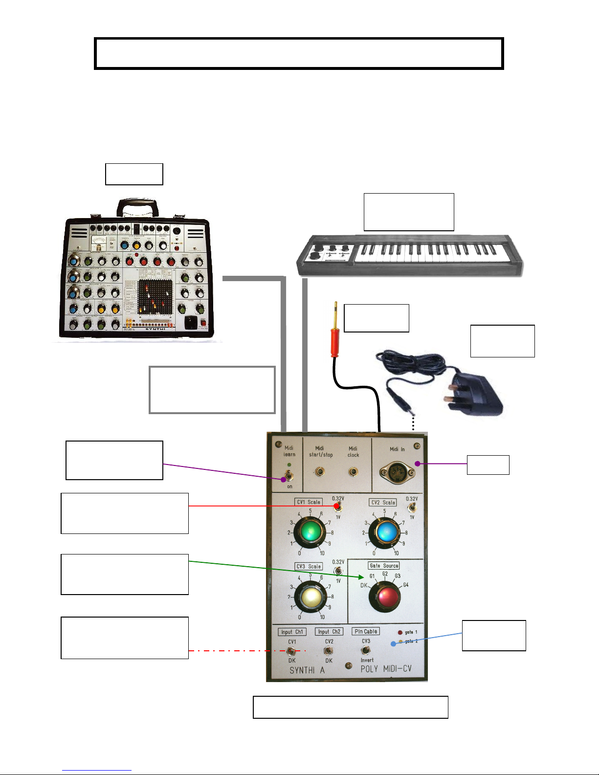
Switches for DK1/2 or Midi-CV
channel control
Gate Source switch:
Switches between
DK
, midi gates1
-4
Toggle switches for switching
between 1V/Oct or 0.32V/Oct
Synthi A
Synthi
A
POLY
MIDI
-
CV
SYNTHI
A
POLY
MIDI
-CV
INTERFACE
Interface Cables
1x8 way Jones (male)
1x8 way Jones(female)
Midi Learn/Midi
Activity switch
and
LED
Midi In
DK1/2 Keyboard
(optional)
Inverts CV3
voltage
special pin
cable
12v AC/DC
Adapter
Page 2

2
Instructions on using the Synthi A Poly Midi-CV Interface
This is a Poly Midi-CV (PMCV) unit designed to be used with an EMS Synthi A, either with or
without a Dk1/2 keyboard. It is based around Marc Bareille’s fantastic 3-channel micro-controller
based Midi-CV converter called the ‘MCV876’ (which Marc has kindly allowed me to incorporate in
the modules)
See details of Marc’s unit and all its many features at his website:-
http://m.bareille.free.fr/mcv876/mcv876.html
The latest units I ship have the most recent firmware (v3.06 as of October 2010) for the
Pic18F2320 microcontroller which has faster better performance than the older models (based on
Pic16F876 microcontrollers).
Before Power On
With the Synthi powered off, plug in the two grey cables with the 8 way ‘Jones’ plugs at each end.
The male Jones plug to the ‘keyboard’ socket on the Synthi A, and the female to the DK1/2
keyboard (if you have one). The PMCV unit allows independent switching between a connected
DK keyboard and midi control, through front panel toggle switches. Switch on the Synthi A. Then
plug in the ac power adapter into the rear of the PMCV. You will see the green midi activity led
(top left) flash a few times to indicate all is well.
The midi-cv board in the PMCV is powered by the external ac adapter. But also some power from
the -9V power rail is taken from the Synthi A (via the Jones plug cables) but only a few milliamps.
This is needed for the CV3 voltage inverter. The reason an ac adapter is used is because the Synthi
A has a weak internal psu compared to the later Synthi AKS (and VCS3(mk2)). These latter units
were meant to be able to power external sequencers, so the internal psu is much stronger than in
the Synthi A/VCS3(mk1).
N.B. The toggle switch at top left IS NOT A POWER ON/OFF SWITCH! It is the Midi learn switch
(discussed below) and it should always be kept in the off (up) position in normal use.
The PMCV has no on/off power switch. It is powered on/off when the ac adapter is plugged or
unplugged and when the Synthi is switched on/off.
The Midi Activity Led (green)
This is a multi-purpose led! The led blinks a few times at power on. Then the led will monitor all
incoming recognised MIDI status bytes. The led also blink 3 long blinks if the interface receives the
"Write To Flash" sysex message. When this message is received, all PMCV parameters are written
into the flash RAM. So the PMCV can recall a setup even after a power off. When the interface is
in MIDI Learn mode, the led stays on, until a MIDI message has been received and learned by the
interface. In ‘mono’ play mode (see play modes description below) the midi activity led flashes
when midi notes are received. In other play modes it remains off when midi notes are
Page 3

3
sent..this is simply to speed up the mid -> cv conversion in polyphonic and multi play modes
where every bit of processing speed is ‘squeezed’ out of the microcontroller.
The "Midi learn" switch
To place the unit in midi learn mode toggle the midi learn switch on then off (down and back up).
The midi activity led stays on until a MIDI message has been received and learned by the interface.
The led will blink 3 long blinks if the interface receives the "Write To Flash" sysex message and will
then automatically go out of midi learn mode to midi play mode.
If you wish to come out of midi learn mode without sending any new configuration data just
toggle the midi learn switch down and up once more. Then the led will switch off and the unit is in
the standard play mode.
Here is how Midi learn works:
When you toggle the Midi Learn switch down then back up the midi activity led stays on and the
PMCV is in Learn Mode waiting to receive a Midi message containing Midi channel information.
When a message arrives ( you play a note on the master keyboard for example) , the Midi channel
number is extracted, compared to the actual interface Midi channel and set to this new value if
different. If the Midi channel of the message is identical to the one configured into the interface,
and if the message received is a Midi note ON message, the interface extracts the Midi number of
the note played and sets this value as the reference (base or lowest ) note. This allows transpose
of the PMCV to any note on the keyboard. The reference note is the Lowest note the interface can
play ( digital zero).
Using the small Windows configuration programme available from Marc’s website you can
configure the unit to any of the available play modes mode as you desire.
V3.06 Firmware and different Play Modes
The PMCV can be configured in these different playmodes using the windows configuration
programme (version 3) which is available from http://m.bareille.free.fr/mcv876/mcv876.html
Page 4
4
Mono
• CV1-Gate1 assigned to Note On/Off messages
• CV2, CV3,CV4* are assignable to controllers, velocity or PitchBend..
• Gates 2,3,4 are assignable to controllers.
• One channel recognition
Multi2
• CV1/Gate1 and CV2/Gate2 are on channel N - CV1 assignable to MIDI notes
• CV3/Gate3 and CV/Gate4 are on channel N+1 - CV4* assignable to MIDI notes
Multi4
• CV1 to CV4*and Gate1 to 4 are respectively on channels N to N+4
• CVs or gates can be assigned to MIDI notes or controllers independently.
Poly2
• CV1 +Gate1 and CV2+Gate2 are assigned to Note On/Off messages
• CV3 and CV4* are assignable to controllers, velocity or PitchBend..
Poly4
• CV1 to CV4* and Gate1 to 4 are assigned to Note On/Off message
*note CV4 is only available on the 4-channel Quad Midi-CV units.
Triggering the Synthi A Envelope Shaper
The PMCV has Envelope Shaper (ES) trigger assignable to either keyboard (DK1 or DK2 if present)
or any of the 4 gates (gate1-gate4) via a front panel rotary switch. How many of the 4 gates are
available depends on the mode used (see above). E.g. in Poly2 mode, only 2 gates are available
(gate1 and gate2). In poly 4 mode (Quad Units only) or Controller mode all 4 gates are available to
trigger the ES.
Red and yellow panel LED’s light when midi Gate 1 and/or Gate2 are triggered.
Gate 5 and gate 6 outputs are via jack sockets and offer Midi start/Stop and Midi clock signals for
interfacing and synchronizing with other external midi devices.
Using the front panel CV Scaling Potentiometers
CV1-CV3 can be scaled using the 3 front panel potentiometer knobs. These allow different
response to midi generated control voltages. Of particular importance is the fact that EMS Synthi
oscillators use 0.32V/Octave standard NOT 1V/Octave as on most other synths. For pitch CV1 it is
necessary to switch the toggle switch to the 0.32V/Oct setting and scale knob set to maximum
value 10. This will produce correct chromatic scales on Osc1 and Osc2. For CV2 and CV3 you can
either use 0.32V or 1V/Oct setting as you wish for different responses.
The 1V/Oct option is useful if a CV channel is being used as a modulation source rather than to
generate pitch control of a Synthi oscillator. Also if your Synthi oscillators 1 and/or 2 are not
exactly scaled to 0.32V/Oct.. use the 1V setting and adjust the scaling pots until you get proper
chromatic pitches.
Page 5

5
NEW FEATURE FOR 2011: precision multi-turn trimmers for fine tuning of
0.32V/Oct scaling of CV1-CV3.
On the rear of all Midi-CV units produced from Nov 2010 onwards, you will find 3 multi-turn
trimmers. These are adjusted by inserting a small flat head screwdriver. They are labelled:-
The purpose of these trimmers is that on many Synthi’s, Osc1 and Osc2 scaling is not precisely
0.32V/Oct (unless it’s just been serviced). This results in out of tune or non-chromatic pitch scaling
even if pitch cv at 0.32V/Oct is used to control Osc1/2 frequency. These trimmers allow you to get
around this problem.
By default the trimmers are adjusted so that when CV1-CV3 pots are set at 10 on the front of the
unit AND the 3 toggle switches are set to 0.32V/Oct, then pitch CV1-CV3 are scaled at 0.32V/Oct.
If you find that your Synthi A sounds out of tune when you patch e.g. CV1 to Osc1 and CV2 to
Osc2 freq. control using matrix patch pins then do the following calibration. What follows assumes
the play mode of the unit is Poly2 .
Osc1/CV1
Make sure the Synthi A is warmed up first (at least 15mins)
Set Input ch1 pot on the Synthi A to max 10 and Osc1 frequency to some suitable value. Set up
the following patch:
Note the above image shows the patch for mk2 matrix.
0.32V/Oct Adjustment
CV1
CV2
CV3
Page 6

6
Set the CV1 scale pot to 10 on the Poly Midi-CV Unit and the toggle switch to 0.32V/Oct range.
Set the lower toggle switch to the CV1 setting and the gate setting to G1. Plug in a Midi Keyboard
or software sequencer play a sequence of keys/notes at different octaves. If notes sound
flat/sharp...make small adjustments to the first of the rear trimmers labelled CV1 with a small
screwdriver. You should hear the pitches of the notes played change. Doing this you can trim the
0.32V/Oct setting of CV1 to match the scaling of Synthi Osc1 so it tracks chromatically over
several octaves.
Osc2/CV2
Apply the same procedure as above to CV2 and Osc2. The patch will now be as above but the black
pin connects Osc2 out to Output ch1 and the red precision pin connects Input Ch2 to Osc2
frequency control.
Make sure Input ch2 level pot is set at 10 on the Synthi A.
Set the CV2 scale pot to 10 on the Poly Midi-CV Unit and the toggle switch to 0.32V/Oct range.
Set the lower toggle switch to the CV2 setting and the gate setting to G2. Plug in a Midi Keyboard
or software sequencer play a sequence of keys/notes at different octaves. This time to trigger G2
and midi note 2 pitch CV (which is CV2) you need to hit 2 keys at the same time.
In poly2 mode ..the unit is duophonic so that when 2 keys are struck at once it assigns lower note
to CV1/Gate1 and upper note to CV2/Gate 2. We want to trim the CV2 0.32V/Oct so you need to
hit 2 keys (e.g. 2 keys next to each other on the midi keyboard is easiest) to trigger gate G2 and
CV2. If you hit just one key you will only trigger G1 and only Cv1 will change as you play different
single notes.
Now whilst playing these two keys transpose the midi keyboard up an octave or down and octave.
If the notes heard through the Synthi A sound flat/sharp...make small adjustments to the second
of the rear trimmers with a small screwdriver. You should hear the pitches of the notes played
change. Doing this you can trim the 0.32V/Oct setting of CV2 to match the scaling of Synthi A Osc2
so it tracks chromatically over several octaves.
The fine tuning of CV3 scaling is less critical unless you intend on using CV3 to act as pitch CV for
controlling Osc3 in the audio range. You will need to put the unit in Poly4 play mode if you want to
use this option because In this mode CV1-CV4 (CV4 only available on Quad Midi units)
correspond to pitches of Midi notes 1-4. For changing play modes on the unit see later on in this
guide. Note Osc3 of the Synthi is not (by design) tracking at 0.32V/Oct but at 0.26V/Oct (!) so you
will need to adjust the third trimmer on the rear of the unit rather more than for CV1 and CV2 to
get the scaling down to 0.26V/Oct. Other than this the procedure is as above but the patch should
now take Osc3 to Output Ch1 and CV3 to Osc3 freq. control. which is achieved by inserting the
special pin cable anywhere in the Osc3 freq ‘column’ of the matrix.
Switch the gate selection control to G3 and then hit 3 simultaneous keys on your midi keyboard.
This will generate CV1-CV3 pitch CV’s and trigger G1-G3 (only G1 and G2 have Led’s that light ).
Apply transpose to the 3 keys you are simultaneously hitting to test chromatic scaling of Osc3 and
adjust the third trimmer as necessary.
Page 7

7
Finally, You will have to have the inverter toggle switch in the on ‘invert’ position. Otherwise you
will find Osc3 plays ‘backwards’..i.e. playing a higher key on the keyboard (hence a larger positive
CV3 voltage) generates a lower note (and vice-versa). The reason is a bit technical but it’s to do
with the fact that all 3 Synthi Oscillators actually track using a –ve CV (NOT Positive CV which is the
norm for most other synths). Since Input Ch1/2 invert voltages fed into them (they are inverting
amplifiers) positive midi-generated CV1 and CV2 get inverted to –ve CV by them. But row 16 (the
third Input channel) does not invert..hence the reason why I designed the unit to allow inverting
of CV3.
Lower Toggle Switches
Lower toggle switches allow independent switching of DK control (if one is connected) or Midi-CV
control of each of the 2 independent CV input channels into the matrix (Input Ch1, Input Ch2).
There is also the option to invert CV3 via another toggle switch..again adding to the creative
possibilities.
Pretty much any multi-tracking software/hardware sequencer or a Midi keyboard will work with
the PMCV. Software sequencers (e.g. those used in Cubase etc) allow the drawing of ‘envelope
shapes’ for Midi continuous controller messages. These will then create dynamic envelopes (e.g.
for velocity, PitchBend, modulation wheel etc) that can be used for any/all of CV1-CV3.
Creating Patches Using the Unit
CV1 enters the Synthi matrix via Input ch1 and CV2 via input ch2. It’s best to have the Input Ch1 and
Input Ch2 pots on the Synthi set to their maximum value 10. CV3 is available to he matrix via the
special pin cable. There are two pins on the end of this cable which can be inerted into any columns of
the matrix. Note this operation has no affect on the rows they are inserted into.
Using the Windows Configuration Program to change Play Modes
The different play modes of the Poly and Quad Midi-CV units are accessed via sysex messages sent to
the unit through a midi cable connected to e.g. a USB or other midi interface running on a Windows
PC/laptop. The programme (and any future updates) is available from Marc Bareille’s website:-
http://m.bareille.free.fr/mcv876/mcv876.html
Input Ch1
Input Ch
2
S
pecial Pin cable
CV1
CV2
CV3
Page 8

8
Make sure you download version 3 of the programme. It is also included on the CD when you
purchased your Poly Midi-CVunit.
On running the programme the following screen appears:-
There are just 3 main tabs. Click on ‘Midi’ tab to setup the midi out port on your PC :-
In the above a 1x1 Midi Sport USB midi inteface is being used.
Must choose
this option
Make sure this
corresponds to
the midi out
you are using
to connect to
the Poly Midi
CV
Page 9

9
It is very important you tick the ‘PIC 18F2320 -40MHz ‘ button..as all my midi cv units use this
processor and firmware v 3.x
Aslo click the ‘send parameters in real time’ button as this speeds up the process of changing play
modes. There are other options to the right concerning midi inputs that you dont need worry about for
basic operation.
Now click the main Config tab which is where you can choose the different play modes
* Note the labelling of the 4 DAC’s is DAC0-DAC3 (as opposed to DAC1-DAC4 ) in the configuration
program. Also only 3 of the 4 DAC’s are present on Poly Midi units so you may ignore the fourth DAC
setting.
‘
presets
’ where you can
save your favourite play
modes settings for quick
change
click to send sysex message
directly to the Poly MidiCV Unit and change the
play mode
‘write to Flash’ button.
click to save the chosen play
mode into the flash memory
of the Poly Midi-CV
Play mode choice
Midi Chan.
Lowest midi note
Poly MCV Unit
responds to
4 Digital to
analogue
converters (DAC’s)
corresponding to
CV1-CV4 *
‘PB’=pitch bend
limits maximum
CV to +5V
‘VL’=Note Velocity
Page 10

10
You just have to remember that DAC0-DAC2 correspond to CV1-CV3 as used in this guide. Similarly
you will notice that Gate1-Gate4 are labelled as ‘Gate0-Gate3’ in the program.
In the above example, if the send to flash button is clicked the Poly Midi Unit would be set to Poly2
play mode. This means CV1 corresponds to Midi note 1 and gate G1 is triggered by Midi note 1 on
message; CV2 corresponds to Midi note 2 and Gate 2 is triggered when Midi note 2 on message is
received. Meanwhile CV3 is set to Pitch Bend (green box). Finally for Quad Midi-CV units only a
fourth CV channel is available, CV4, and in this example it corresponds to the Midi Volume (Coarse) CC.
In addition the ‘+5V’ option is also checked, which means the maximum swing of CV4 = +5v. So a Midi
Volume value of 0 gives 0V on CV4 whereas a Midi Volume value of 128 sets CV4 to +5V. Limiting the
maximum swing to +5V can be useful and give better resolution/response depending on what control
destination on the Synthi matrix you are routing the CV.
Notice in this example all the text in the first 3 DAC boxes is greyed and CC boxes are ‘unchecked’.
This is because we have used up 3 DAC assignments. Two are used for Midi note 1 and Midi note 2 CV,
the third on Pitch Bend CV. For Poly Midi units this exhaust all the 3 channels of CV available. On Quad
Midi-CV units we still have CV4 (DAC3) which to freely assign a Midi CC. Similarly looking at the Gate
CC’s assigned. G1 and G2 are greyed out because they are automatically assigned to Midi note1 and
note 2 ‘on’ events. This leaves G3 and G4 assignable to a Midi CC.
Here is another example which sets the Midi-CV Unit again to Mono play mode.
Thus CV1 is automatically assigned to midi note1 value. This leaves CV2-CV4 (CV2-CV3 for Poly Midi
units) freely assignable to PB, VL, or a CC. In the example CV2 is assigned to Modulation Wheel
(Coarse) CC, CV3 to Pitch Bend and CV4 to Expression (Course) CC. In addition maximum swing of CV3
and CV4 is limited to +5v.
Page 11

11
G1 is automatically assigned to Midi note 1 on message. But G2-G4 can be freely assigned to Midi CC’s.
In the example G2-G4 are assigned to controllers 15, 20 and 21.
Finally, if you click either the ‘send to Midi’ or ‘Write to Flash’ buttons you will see the Midi activity led
flash briefly as the processor is updated. Writing to Flash means the unit will remember the play
mode change even after power down.
Steve Thomas
Digitana Electronics, St Albans, England, 2012.
Copyright Digitana Electronics , England.
 Loading...