

Page 1
SYNTEC 6A Controller Hardware Specifications
This document is only for Engineering Department
- 1 -
Description:
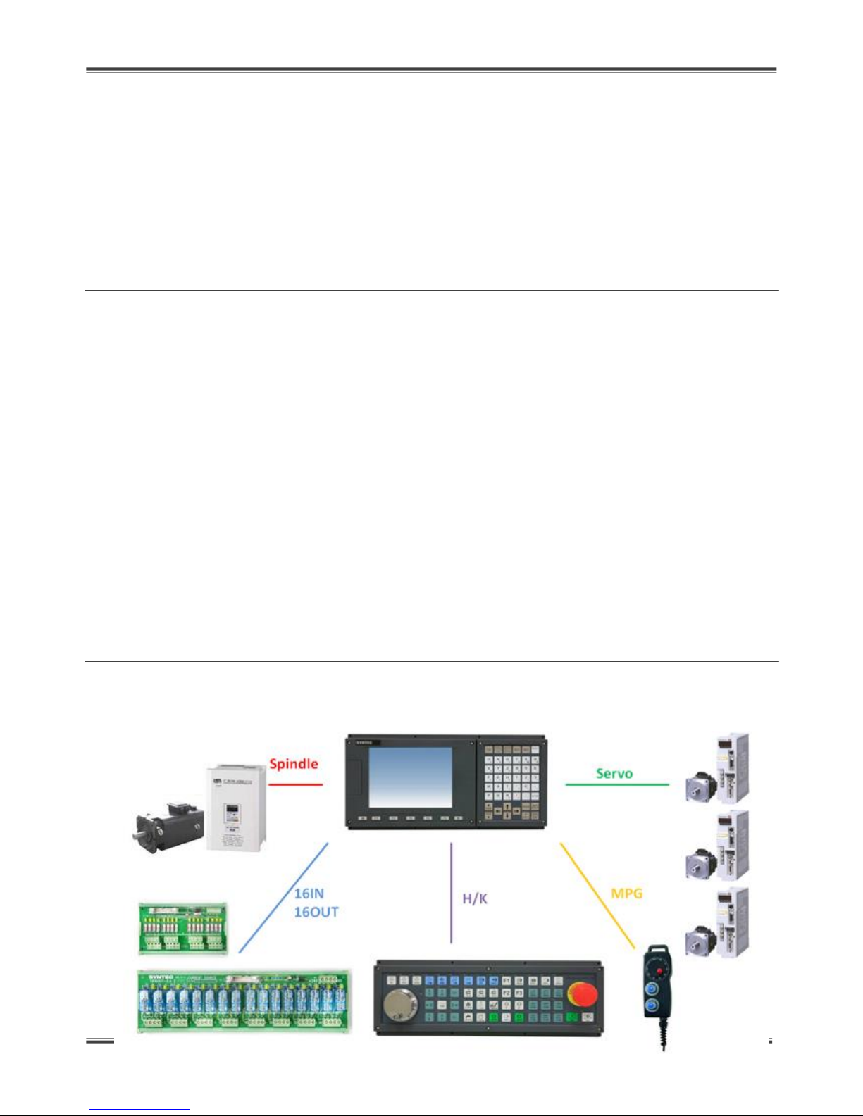
The Syntec 6A Series Controllers are based on embedded systems architectures and are
equipped with 8-inch LCD displays and universal text key panels. The systems come with
integrated servo axes, spindles, and hand wheels. USB ports are also available on the front
panel. This series provides high stability, ease of use, and high reliability at a low price.
General Specifications:
●3-axis servo positioning and control
●Universal text key panel
●1 spindle DA (+/-10V), including one Encoder
●Dedicated matrix scan port on the operation panel
●1 dedicated hand wheel axis, including 7 IN signals
●2 USB ports are provided on the front panel, supporting hot swapping
●16 Direct Input points
●Adapter ( 100~240V AC 50/60Hz ) included
●16 Direct Output points
●Operating ambient temperature 55°C
System Roadmap:
Page 2
SYNTEC 6A Controller Hardware Specifications
This document is only for Engineering Department
- 2 -
Mechanical Specifications:
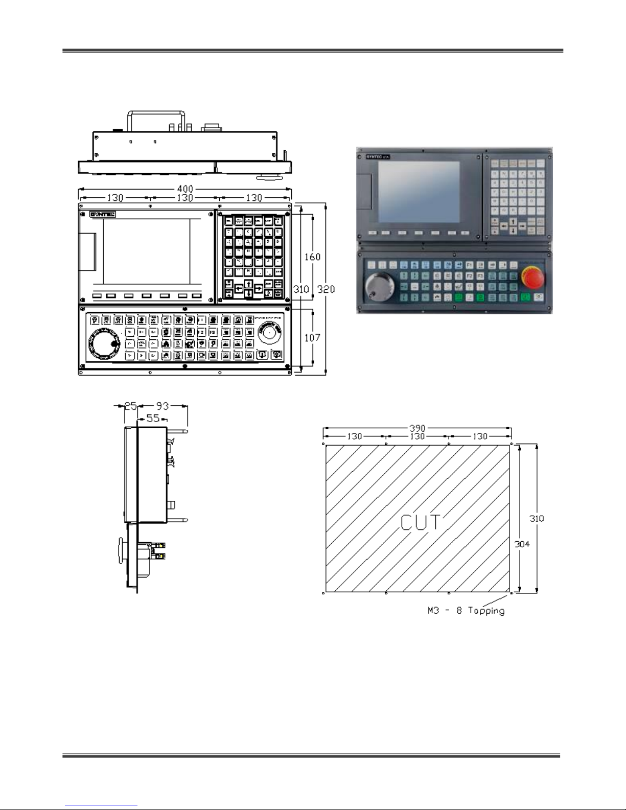
6A-4012-T2 Structural Dimensions Diagram
◆◆ IInnssttaallllaattiioonn HHoollee SSiizzee SSppeecciiffiiccaattiioonnss ((uunniittss:: mmmm))
Page 3

SYNTEC 6A Controller Hardware Specifications
This document is only for Engineering Department
- 3 -
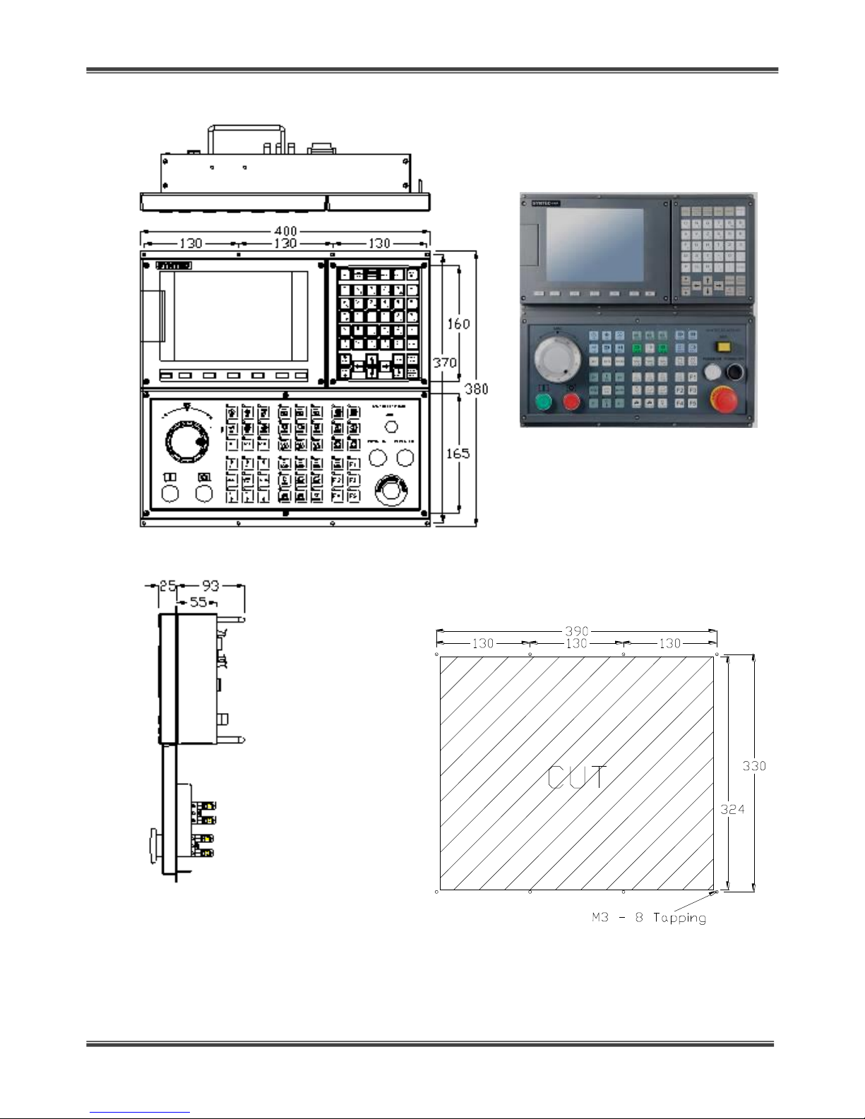
6A-4012-M Structural Dimensions Diagram
◆◆ IInnssttaallllaattiioonn HHoollee SSiizzee SSppeecciiffiiccaattiioonnss ((uunniittss:: mmmm))
Page 4
SYNTEC 6A Controller Hardware Specifications
This document is only for Engineering Department
- 4 -
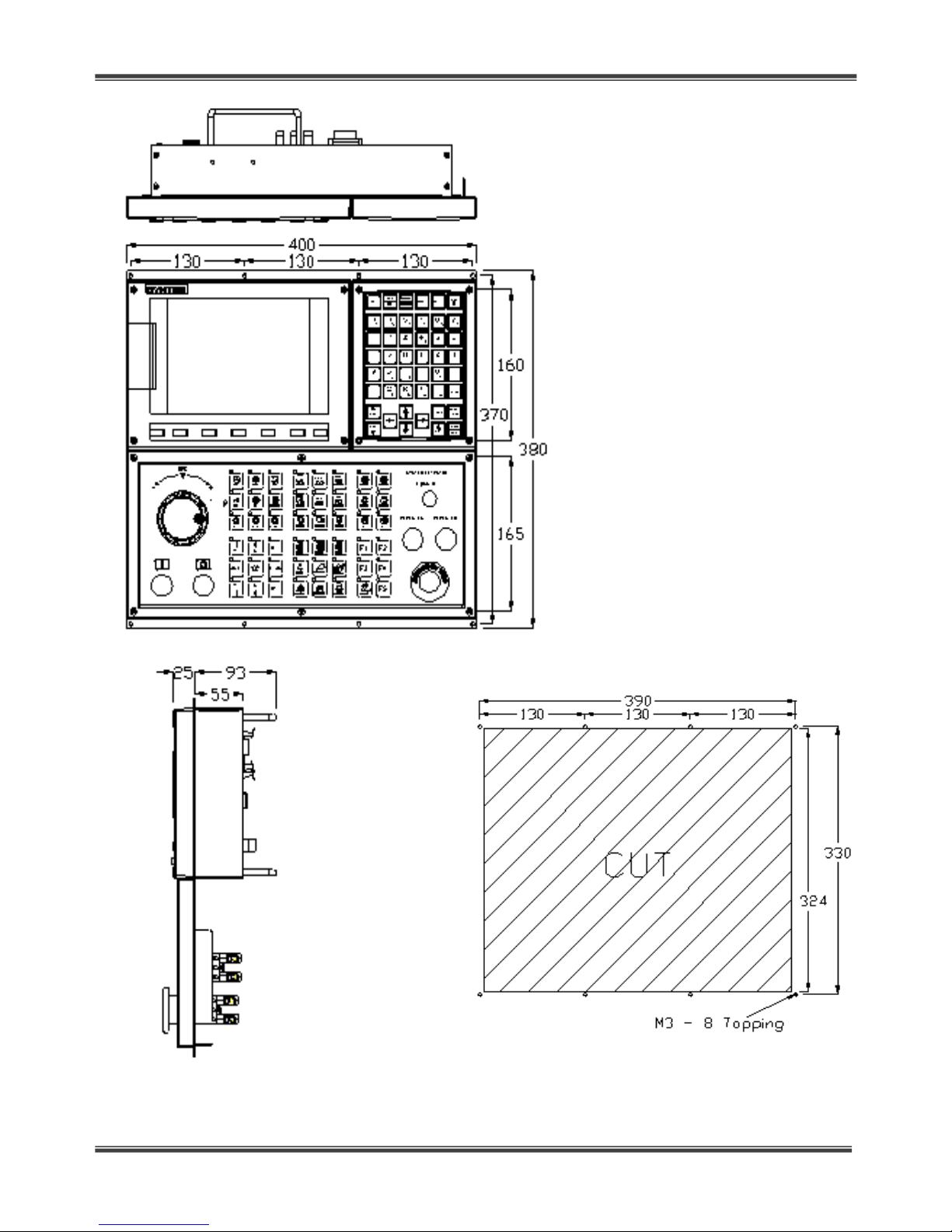
6A-4018-M2 Structural Dimensions Diagram
◆◆IInnssttaallllaattiioonn HHoollee SSiizzee SSppeecciiffiiccaattiioonnss ((uunniittss:: mmmm))
Page 5
SYNTEC 6A Controller Hardware Specifications
This document is only for Engineering Department
- 5 -
6A-4018-T3 Structural Dimensions Diagram
◆◆IInnssttaallllaattiioonn HHoollee SSiizzee SSppeecciiffiiccaattiioonnss ((uunniittss:: mmmm))
Page 6

SYNTEC 6A Controller Hardware Specifications
This document is only for Engineering Department
- 6 -
12
1920
Connector Pindefine:
External Input Interface (X1):
The controller itself provides a total of 16 I digital input signals to use with the MLC.
Direct connections can be made to various types of test and sensor devices (such as
proximity switches, micro switches, etc..) for use with the TB16IN, thereby simplifying wiring.
●This is a Source input. (Commonly known as: positive common +COM)
Internal circuit
●We also provide input terminal block modules (TB16-IN) with finished wires, which you
are welcome to take advantage of.
●If you do not wish to use TB16-IN, you can also connect your own wires.
●Standard wire lengths: 1.8M 3.5M 5.5M 8M.
●Input terminal block module (TB16-IN) support information:
Pin
Signal
Pin
Signal
01
--
02
--
03
GND
04
GND
05
Input 7
06
Input 15
07
Input 6
08
Input 14
09
Input 5
10
Input 13
11
Input 4
12
Input 12
13
Input 3
14
Input 11
15
Input 2
16
Input 10
17
Input 1
18
Input 9
19
Input 0
20
Input 8
Terminal block
Wiring
Page 7

SYNTEC 6A Controller Hardware Specifications
This document is only for Engineering Department
- 7 -
12
1920
External Output Interface (Y1):
Direct connections can be made to various driving switches (such as electromagnetic
contactors, relays, etc.) for use with TB16OUT, thereby simplifying wiring.
●This is a Source input. (Commonly known as: positive common +COM); each Output
has its own independent short-circuit protection. When the short-circuit protection is
triggered, the external load is cut off. The operational current allowed for each output point is
150 mA; please do not exceed this limit.
Internal circuit
●We also provide input terminal block modules (the TB16-OUT Series) with finished
module
specifications
TB16IN-PHO
Supports SOURCE
and SINK
TB16IN
Supports SOURCE
Pin
Signal
Pin
Signal
01
24V
02
24V
03
GND
04
GND
05
Output 7
06
Output 15
07
Output 6
08
Output 14
09
Output 5
10
Output 13
11
Output 4
12
Output 12
13
Output 3
14
Output 11
15
Output 2
16
Output 10
17
Output 1
18
Output 9
19
Output 0
20
Output 8
Page 8

SYNTEC 6A Controller Hardware Specifications
This document is only for Engineering Department
- 8 -
wires, which you are welcome to take advantage of.
●If you do not wish to use TB16-OUT, you can also connect your own wires.
●Standard wire lengths: 1.8M 3.5M 5.5M 8M.
●Output terminal block module (TB16-OUT) support information:
Operation Panel Matrix Scan Interface (H/K):
Pin
Signal
Pin
Signal
01
XDO 48
02
XDO 49
03
XDO 50
04
XDO 51
05
XDO 52
06
XDO 53
07
XDO 54
08
XDO 55
09
XDO 56
10
XDO 57
11
XDO 58
12
XDO 59
13
XDO 60
14
XDO 61
15
XDO 62
16
GND
17
VEXT
18
XDI 48
19
XDI 49
20
XDI 50
21
XDI 51
22
XDI 52
23
XDI 53
24
XDI 54
25
XDI 55
26
--
●In terms of application, the matrix scan interface circuit is divided into the Data
Terminal
block module
Wiring specifications
TB16OUT-R8
8 DC/AC relay outputs.
TB16OUT-R8T8
16 outputs, including 8 DC transistor outputs and 8 DC/AC Relay
outputs.
The maximum allowed output for each transistor is 24V/2A; it must
be confirmed before usage that loads will not exceed these limits.
TB16OUT-T16
The maximum allowed DC output for the 16 transistors is 24V/2A.
12
2526
Page 9

SYNTEC 6A Controller Hardware Specifications
This document is only for Engineering Department
- 9 -
1
6
11
5
10
15
line, Scan, and Indicator portions, as shown in the three blocks in the interface circuit
below:
Internal circuit Internal circuit Internal circuit
●Please note that the VEXT and GND power source wirings can only withstand
voltages within the 5VDC ±10% range. We recommend using the 5V European-standard
terminal provided by the controller itself for wiring.
Please do not connect the 24VDC from the machine to the HardKey European-standard
power source terminal.
Servo Control Interface (P1~P3):
Pin
Signal
Pin
Signal
Pin
Signal
1
A+ 6 Z-
11
CW+
2
A- 7 ALM+(+24V)
12
CW-
3
B+ 8 ALM-(GND)
13
CCW+
4
B- 9 SERVO-ON
14
CCW-
5
Z+
10
SERVO-CLR
15
OUT_COM
Page 10

SYNTEC 6A Controller Hardware Specifications
This document is only for Engineering Department
- 10 -
1
6
11
5
10
15
Servo axis P-COMMAND wiring schematic diagram:
We recommended that you check that the ALM+ and ALM- signal wires are properly
connected before operating the machine.
Dedicated Hand Wheel Interface (MPG):
A
A/
B
B/
Z
Z/
ALM+
ALMSER-ON
SER-CLR
CW+
CWCCW+
CCWCOM
1:A+
2:A-
3:B+
4:B-
5:C+
6:C-
7:ALM+
8:ALM-
9:SER-ON
10:SER-CLR
11:CW+
12:CW-
13:CCW+
14:CCW-
15OUT-COM
SERVO DRIVER
P1~P3
SERVO MOTOR
SYNTEC 6A
Page 11

SYNTEC 6A Controller Hardware Specifications
This document is only for Engineering Department
- 11 -
Line driver MPG hand wheel wiring schematic diagram (Future Life EHDW-(E~F)SERIES)
Pin
Signal
Pin
Signal
Pin
Signal
1
MPG_A+
6
MPG_Z-
11
IN60
2
MPG_A-
7
IN56
12
IN61
3
MPG_B+
8
IN57
13
IN62
4
MPG_B-
9
IN58
14
GND
5
MPG_Z+
10
IN59
15
VCC(+5V)
3:A
5:A/
4:B
6:B/
7:AXIS 1
8:AXIS 2
9:AXIS 3
10:AXIS 4
11:RATE*1
12:RATE*10
13:RATE*100
2:DC0V
1:DC POWER
1:A+
2:A-
3:B+
4:B-
7:XDI56
8:XDI57
9:XDI58
10:XDI59
11:XDI60
12:XDI61
13:XDI62
14:GND
15:VCC(+5V)
MPG
P5
SYNTEC 6A
SYNTEC 6A
Page 12

SYNTEC 6A Controller Hardware Specifications
This document is only for Engineering Department
- 12 -
Open collector MPG Hand Wheel Wiring Schematic Diagram (Future Life
EHDW-B(A~C)SERIES)
The MPG port on the controller can withstand a maximum loading of 5V/250mA from the hand
wheel; please do not use for other purposes.
3:A
4:B
7:AXIS 1
8:AXIS 2
9:AXIS 3
10:AXIS 4
11:RATE*1
12:RATE*10
13:RATE*100
2:DC0V
1:DC POWER
1:A+
2:A-
3:B+
4:B-
7:XDI56
8:XDI57
9:XDI58
10:XDI59
11:XDI60
12:XDI61
13:XDI62
14:GND
15:VCC(+5V)
MPG
P5
SYNTEC 6A
Page 13

SYNTEC 6A Controller Hardware Specifications
This document is only for Engineering Department
- 13 -
1
6
11
5
10
15
Spindle Interface + Encoder (SP) Spindle Commands (Spindle)
Spindle Wiring Schematic Diagram
Pin
Signal
Pin
Signal
1
A+ 9 DA+
2
A-
10
DA-
3
B+
11
SP_FWD (O46)
4
B-
12
SP_REV (O47)
5
C+
13
SP_COM
6
C-
14
GND
7
ALM+
15
5V 8 ALM-
Pin
Signal
1
SP_FWD (O46)
2
SP_REV (O47)
3
SP_COM
4
--
5
ALM+
6
ALM-
7
DA+
8
DA-
8
1
Forward ad Reverse Spindle
Rotation Interface Circuit
Spindle Motor
A
A/
B
B/
Z
Z/
ALM+
ALMAVI
ACM
FWD
REV
DCM
ENC_GND
ENC_5V
1:A+
2:A-
3:B+
4:B-
5:C+
6:C-
7:ALM+
8:ALM-
9:DA+
10:DA-
11: Sp-FWD
12: Sp-REV
13: SP-COM
14:GND-
15:5V
Spindle Inveter
P4
SYNTEC 6A
Page 14

SYNTEC 6A Controller Hardware Specifications
This document is only for Engineering Department
- 14 -
ETHERNET Port
The 6A Series controllers are equipped with a 10/100 BASE network
communications port, allowing you to access data files stored remotely.
 Loading...