


Mainboard User’s Manual
This publication, including all photographs, illustrations and
software, is protected under international copyright laws, with all
rights reserved. Neither this manual, nor any of the material
contained herein, may be reproduced without the express written
consent of the manufacturer.
The information in this document is subject to change without
notice. The manufacturer makes no representations or warranties
with respect to the contents hereof and specifically disclaims any
implied warranties of merchantability or fitness for any particular
purpose. Further, the manufacturer reserves the right to revise this
publication and to make changes from time to time in the content
hereof without obligation of the manufacturer to notify any person
of such revision or changes.
Trademarks
IBM, VGA, and PS/2 are registered trademarks of International
Business Machines.
Intel, Pentium/II/III, MMX, and Celeron are registered trademarks
of Intel Corporation.
Microsoft, MS-DOS and Windows 95/98/NT/2000/XP are
registered trademarks of Microsoft Corporation.
PC-cillin is a trademark of Trend Micro Inc.
Award is a trademark of Award Software Inc.
Other names used in this publication may be trademarks and are
acknowledged.
Copyright © 2003
All Rights Reserved
8601a Series, V1.3
V133X/August 2003

Mainboard User’s Manual
Notice:
Owing to Microsoft’s certifying schedule is various to every
supplier, we might have some drivers not certified yet by
Microsoft. Therefore, it might happen under Windows XP that a
dialogue box (shown as below) pop out warning you this software
has not passed Windows Logo testing to verify its compatibility
with Windows XP. Please rest assured that our RD department has
already tested and verified these drivers. Just click the “Continue
Anyway” button and go ahead the installation.
II

Mainboard User’s Manual
Table of Contents
Trademarks.............................................................................. I
Chapter 1: Introduction....................................................................1
Key Features............................................................................2
Package Contents.....................................................................5
Static Electricity Precautions...................................................6
Pre-Installation Inspection.......................................................6
Chapter 2: Mainboard Installation...................................................7
Mainboard Components ..........................................................8
I/O Ports...................................................................................8
Install Memory ........................................................................8
Setting Jumper Switches........................................................10
Install the Mainboard.............................................................12
Optional Extension Brackets.................................................13
Install Other Devices.............................................................14
Expansion Slots.....................................................................17
Chapter 3: BIOS Setup Utility.......................................................19
Introduction ...........................................................................19
Running the Setup Utility......................................................20
Standard CMOS Features Page .............................................21
Advanced BIOS Features Page..............................................22
Advanced Chipset Features Page ..........................................24
Integrated Peripherals Page...................................................26
Power Management Setup Page............................................29
PnP/PCI Configurations Page................................................31
Hardware Monitor Page.........................................................32
Frequency/Voltage Control Page...........................................33
Load BestPerf. Defaults.........................................................33
Load Optimized Defaults.......................................................34
Set Password..........................................................................34
Save & Exit Setup .................................................................34
Exit Without Saving..............................................................34
Chapter 4: Software & Applications .............................................35
Introduction ...........................................................................35
Installing Support Software...................................................36
Bundled Software Installation...............................................38
III

Mainboard User’s Manual
IV

1: Introduction
Chapter 1
Introduction
This mainboard has onboard VIA Samuel2 1.2Giga Pro processor
with front-side bus speeds of 133MHz.
This mainboard uses the VIA VT133 chipset, and integrates a 3D
Graphics Accelerator and Ultra DMA 33/66/100 (VT82C686B
chip only) function. The mainboard has a built-in AC97 Codec,
provides an AMR (Audio Modem Riser) slot to support Audio and
Modem application, and has a built-in 10BaseT/100BaseTX
Network Interface. In addition, the mainboard has an extended set
of ATX I/O Ports including PS/2 keyboard and mouse ports, two
USB ports, a parallel port, a VGA port, a serial port, a game port
and audio ports. An extra USB header gives you the option of
connecting two more USB ports.
This mainboard has all the features you need to develop a powerful
multimedia workstation. The board is Micro ATX size and has a
power connector for an ATX power supply.
1

Mainboard User’s Manual
Key Features
The key features of this mainboard include:
C3 Pro Processor
♦ Built-in VIA C3 Samuel2 1.2Giga Pro CPU
♦ Supports up to 133MHz Front-Side Bus
Memory Support
♦ Two DIMM slots for 168-pin SDRAM memory modules
♦ Support for 100/133 MHz memory bus
♦ Maximum installed memory is 2 x 512MB = 1GB
Expansion Slots
♦ One AMR slot for a special audio/modem riser card
♦ Three 32-bit PCI slots for PCI 2.2-compliant bus interface.
♦ One 8/16-bit ISA slot.
Onboard IDE channels
♦ Primary and Secondary PCI IDE channels
♦ Support for PIO modes, Bus Mastering and Ultra DMA
33/66/100 (optional VT82C686B) modes
Power Supply and Power Management
♦ ATX power supply connector
♦ ACPI and previous PMU support, suspend switch
♦ Supports Wake on LAN and Wake on Alarm
Built-in Graphics System
♦ Onboard 64-bit 2D/3D graphic engine and Video
Accelerator with advanced DVD video
♦ 2 to 8 MB frame buffer use system memory
♦ Supports high resolutions up to 1600x1200
2

1: Introduction
AC97 Codec
♦ Compliant AC97 2.1 specification
♦ Supports 18-bit ADC (Analog Digital Converter) and DAC
(Digital Analog Converter) as well as 18-bit stereo fullduplex codec
Built-in Ethernet LAN (optional)
♦ 10BaseT/100BaseTX Ethernet LAN
♦ LAN controller integrates Fast Ethernet MAC and PHY
compliant with IEEE802.3u 100BASE-TX, 10BASE-T and
ANSI X3.263 TP-PMD standards
♦ Compliant with ACPI 1.0 and the Network Device Class
Power Management 1.0
♦ High Performance provided by 100Mbps clock generator
and data recovery circuit for 100Mbps receiver
Onboard I/O Ports
♦ Provides PC99 Color Connectors for easy peripheral device
connections
♦ Floppy disk drive connector with 1Mb/s transfer rate
♦ One serial ports with 16550-compatible fast UART
♦ One parallel port with ECP and EPP support
♦ Two USB ports, and optional two USB ports module
♦ Two PS/2 ports for keyboard and mouse
♦ One infrared port connector for optional module
Hardware Monitoring
♦ Built-in hardware monitoring for CPU & System
temperatures, fan speeds and mainboard voltages
Onboard Flash ROM
♦ Automatic board configuration support Plug and Play of
peripheral devices and expansion cards
3

Mainboard User’s Manual
Bundled Software
♦ PC-Cillin2002 provides automatic virus protection under
Windows 98/ME/NT/2000/XP
♦ Adobe Acrobat Reader V5.0 is the software to help users
read .PDF files.
Dimensions
♦ Micro ATX form factor (24.4cm x 19cm)
4

1: Introduction
Package Contents
Your mainboard package ships with the following items:
The mainboard
This User’s Guide
1 UDMA/66 IDE cable
1 Floppy disk drive cable
Support software on CD-ROM disk
Optional Accessories
You can purchase the following optional accessories for this
mainboard.
Extended USB module
AMR Fax/Modem card
5

Mainboard User’s Manual
Static Electricity Precautions
Components on this mainboard can be damaged by static
electricity. Take the following precautions when unpacking the
mainboard and installing it in a system.
1. Keep the mainboard and other components in their original
static-proof packaging until you are ready to install them.
2. During installation, wear a grounded wrist strap if possible. If
you don’t have a wrist strap, discharge static electricity by
touching the bare metal of the system chassis.
3. Handle the mainboard carefully by the edges. Avoid touching
the components unless it is absolutely necessary. During
installation put the mainboard on top of the static-protection
packaging it came in with the component side facing up.
Pre-Installation Inspection
1. Inspect the mainboard for damage to the components and
connectors on the board.
2. If you suspect that the mainboard has been damaged, do not
connect power to the system. Contact your mainboard vendor
and report the damage.
6

2: Mainboard Installation
Chapter 2
Mainboard Installation
To install this mainboard in a system, follow the procedures in this
chapter:
Identify the mainboard components
Install one or more system memory modules
Verify that any jumpers or switches are set correctly
Install the mainboard in a system chassis (case)
Connect any extension brackets or cables to the mainboard
connector headers
Install any peripheral devices and make the appropriate
connections to connectors on the mainboard
Note:
1. Before installing this mainboard, make sure the jumper JBAT1
is set to Normal setting. See this chapter for information on
locating JBAT1 and the setting options.
2. Never connect power to the system during installation. Doing
so may damage the mainboard.
7
Mainboard User’s Manual
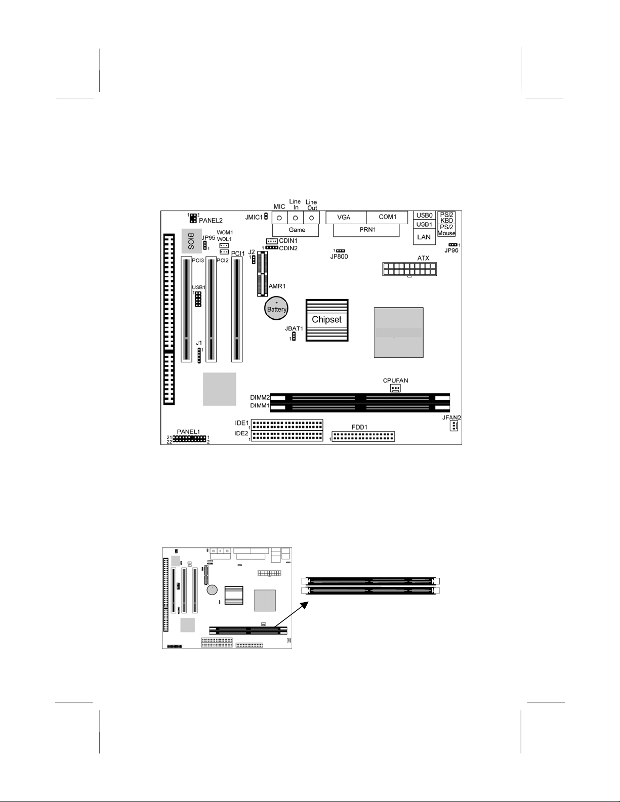
Mainboard Components
Use the diagram below to identify the major components on the
mainboard.
Note: Any jumpers on your mainboard that do not appear in
this illustration are for testing only.
I/O Ports
The illustration below shows a side view of the built-in I/O ports
on the mainboard.
PS/2 Mouse
LAN Port
Parallel Port
VGA Port
Game/MIDI Port
1.2Giga Pro
PS/2 Keyboard
USB Ports
Serial Port COM1/3
Line-Out Jack
Line-In Jack
Microphone Jack
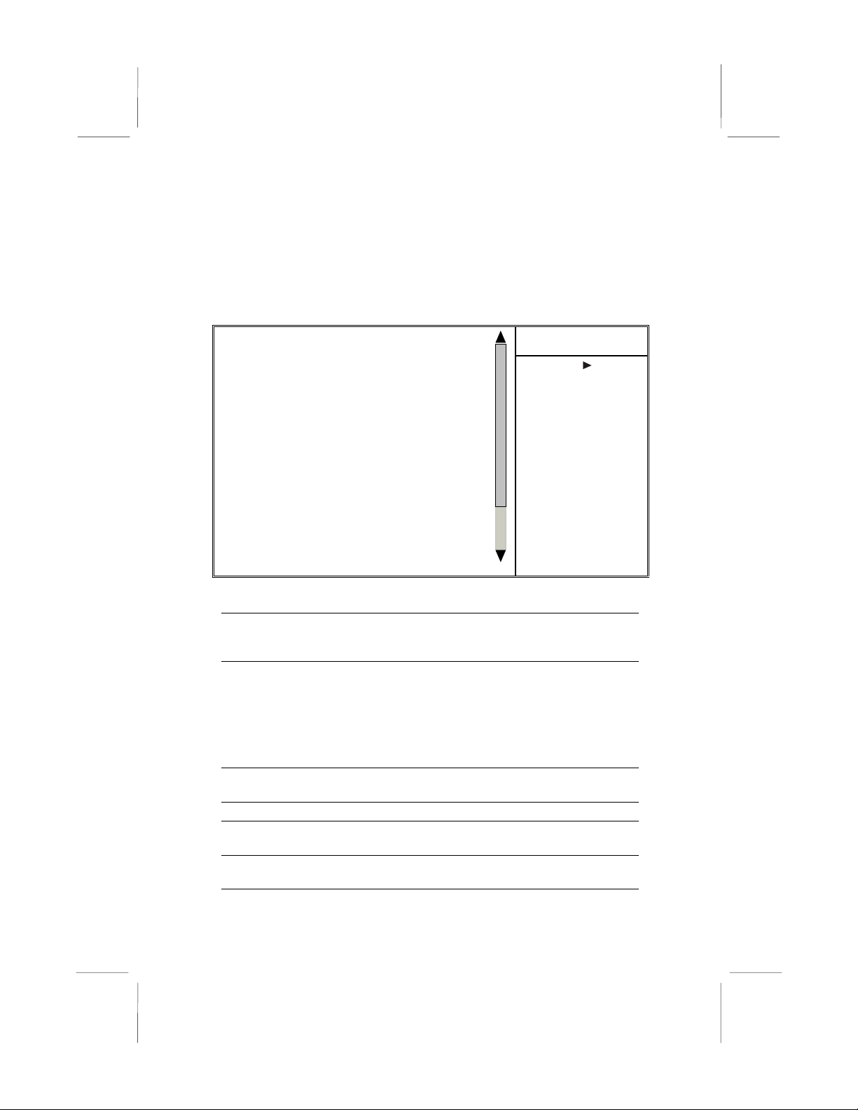
Install Memory
The mainboard has two DIMM sockets for system memory
modules. You must install at least one memory module in order to
use the mainboard.
8
DIMM2
DIMM1

2: Mainboard Installation
For this mainboard, you must use 168-pin, 3.3V unbuffered PC100
or PC133 SDRAM memory modules. You can install any size
memory module from 32 MB to 512 MB, so the maximum
memory size is 2 x 512 MB = 1 GB.
The edge connectors on the memory modules have cut outs, which
coincide with spacers in the DIMM sockets so that memory
modules can only be installed in the correct orientation.
To install a module, push the retaining latches at either end of the
socket outwards. Position the memory module correctly and insert
it into the DIMM socket. Press the module down into the socket so
that the retaining latches rotate up and secure the module in place
by fitting into notches on the edge of the module.
9

Mainboard User’s Manual
Setting Jumper Switches
Jumpers are sets of pins which can be connected together with
jumper caps. The jumper caps change the way the mainboard
operates by changing the electronic circuits on the mainboard. If a
jumper cap connects two pins, we say the pins are SHORT. If a
jumper cap is removed from two pins, the pins are OPEN.
JMIC1
JP95
1
1
J2
Jumper JBAT1: Clear CMOS Memory
Use this jumper to clear the contents of the CMOS memory. You
may need to clear the CMOS memory if the settings in the Setup
Utility are incorrect and prevent your mainboard from operating.
To clear the CMOS memory, disconnect all the power cables from
the mainboard and then move the jumper cap into the CLEAR
setting for a few seconds.
JP96
1
JP800
1
1
JBAT1
Function Jumper Setting
Normal Operation Short Pins 1-2
Clear CMOS Memory Short Pins 2-3
Jumper J2: Codec Selector
Use this jumper to select the onboard audio codec or Audio
Modem Riser (AMR) slot.
Function Jumper Setting
Primary codec onboard Short Pins 1-2
Primary Codec on AMR slot Short Pins 2-3
10

2: Mainboard Installation
Jumper JP95: BIOS Write Protect Selector
Use this jumper to make the BIOS read-only.
Function Jumper Setting
Enable (read only) Short Pins 1-2
Disable Short Pins 2-3
Jumper JP96: Keyboard Power On Selector
If you enable the keyboard power on feature, you can use hot keys
on your keyboard as a power on/off switch for the system.
Note: The system must provide 1A on the +5VSB (+5V Standby)
signal before using the Keyboard Power On function.
Function Jumper Setting
Disable Keyboard Power On Short Pins 1-2
Enable Keyboard Power On Short Pins 2-3
Jumper JP800: Enable/Disable Onboard LAN
The mainboard has a built-in 10BaseT/100BaseTX network
adapter. If you plan on using an alternative network adapter, you
must use this 3-pin jumper to disable the onboard network adapter.
Function Jumper Setting
Disable Onboard LAN Short Pins 1-2
Enable Onboard LAN Short Pins 2-3
Jumper JMIC1: Microphone Type Selector
Use this jumper to select the microphone type that passive one or
the active one input audio to the sound system.
Function Jumper Setting
Passive Microphone Short Pins 1-2
Active Microphone Open Pins 1-2
11

Mainboard User’s Manual
A
Install the Mainboard
Install the mainboard in a system chassis (case). The board is a
micro ATX size mainboard with a twin-tier of I/O ports. Ensure
that your case has an I/O cover plate that matches the ports on this
mainboard.
Install the mainboard in a case. Follow the instructions provided by
the case manufacturer using the hardware and internal mounting
points on the chassis.
TX
PANEL1
Connect the power connector from the power supply to the ATX
connector on the mainboard.
If there is a cooling fan installed in the system chassis, connect the
cable from the cooling fan to the JFAN2 fan power connector on
the mainboard.
If there are a microphone-in jack and/or a speaker-out jack on the
front pannel, connect the cables from the microphone-in and
speaker-out jacks to the PANEL2 header on the mainboard. Then
set the jumper JMIC1 to open setting.
Pin Signal Pin Signal
1 LINEOUT-L 2 MICIN
3 KEY 4 GND
5 LINEOUT-R 6 MICP
PANEL2
2
1
JFAN2
12

2: Mainboard Installation
2
-4-
-3-5-
7
6
-
2
r
Connect the case switches and indicator LEDs to the PANEL1
switch and LED connector header. See the illustration below for a
guide to the header pin assignments.
Pin Signal Pin Signal
1 SPEAKER 2 POWER LED
3 SPEAKER 4 POWER LED
5 SPEAKER 6 POWER LED
7 SPEAKER 8 KEYLOCK
9 KEY 10 KEYLOCK
11 KEY 12 KEY
13 KEY 14 KEY
15 HDD LED 16 HDD LED
17 RESET 18 RESET
19 SUSPEND LED 20 SUSPEND LED
21 POWER BUTTON 22 POWER BUTTON
Power LED
Pins
Keylock
Pins 8-10
6
Reset Switch
Pins 17-18
Power Button
Pins 21-22
2
1
Speaker
Pins 1
HDD LED
Pins 15-1
22
21
Suspend LED
Pins 19
0
Optional Extension Brackets
For this mainboard, you can also obtain a USB module extension
bracket. Install them by following the steps below.
Extended USB Module
This module bracket has two USB ports for more USB devices
(USB port 3-4).
USB1 Heade
1
13

Mainboard User’s Manual
USB1
Pin Signal Pin Signal
1 VCC 2 GND
3 NC 4 UV+
5 UV- 6 UV7 UV+ 8 NC
9 GND 10 VCC
1. Locate the USB1 header on the mainboard.
2. Plug the bracket cable onto the header.
3. In the system chassis, remove a slot cover from one of the
expansion slots and install the extension bracket in the
opening. Use the screw that held the slot cover in place to
secure the extension bracket to the chassis.
Install Other Devices
Install and connect any other devices in the system following the
steps below.
1
1
Floppy Disk Drive
The mainboard ships with a floppy disk drive cable that can
support one or two drives. Drives can be 3.5” or 5.25” wide, with
capacities of 360K, 720K, 1.2MB, 1.44MB, or 2.88MB.
Install your drives and connect power from the system power
supply. Use the cable provided to connect the drives to the floppy
disk drive header FDD1.
FDD1
1
IDE1
IDE2
14

2: Mainboard Installation
2
IDE Devices
IDE devices include hard disk drives, high-density diskette drives,
and CD-ROM or DVD-ROM drives, among others.
The mainboard ships with an IDE cable that can support one or two
IDE devices. If you connect two devices to a single cable, you
must configure one of the drives as Master and one of the drives as
Slave. The documentation of the IDE device will tell you how to
configure the device as a Master or Slave device. The Master
device connects to the end of the cable.
Install the device(s) and connect power from the system power
supply. Use the cable provided to connect the device(s) to the
Primary IDE channel connector IDE1 on the mainboard.
If you want to install more IDE devices, you can purchase a second
IDE cable and connect one or two devices to the Secondary IDE
channel connector IDE2 on the mainboard. If you have two
devices on the cable, one must be Master and one must be Slave.
Internal Sound Connections
If you have installed a CD-ROM drive or DVD-ROM drive, you
can connect the drive audio cable to the onboard sound system.
On the mainboard, locate the two 4-pin connectors CDIN1 and
CDIN2. There are two kinds of connector because different brands
of CD-ROM drive have different kinds of audio cable connectors.
Connect the cable to the appropriate connector.
CDIN1
CDIN
15

Mainboard User’s Manual
CDIN1
Pin Signal
1 CD IN L
2 GND
3 GND
4 CD IN R
CDIN2
Pin Signal
1 GND
2 CD IN R
3 GND
4 CD IN L
Infrared Port
You can connect an infrared port to the mainboard. You can
purchase this option from third-party vendors.
J1-IR Header
1
Pin Signal Pin Signal
1 VCC 2 NC
3 IRRX 4 GND
5 IRTX
1. Locate the infrared port IR header on the mainboard.
2. If you are adding an infrared port, connect the ribbon cable
from the port to the header and then secure the port to an
appropriate place in your system chassis.
16

2: Mainboard Installation
2
A
Expansion Slots
This mainboard has three 32-bit PCI expansion slots, one AMR
slot and one 8/16-bit ISA slot.
Follow the steps below to install a PCI/AMR/ISA expansion card.
1. Locate the AMR, PCI or ISA slots on the mainboard.
2. Remove the slot cover for this slot from the system chassis.
3. Insert the expansion card edge connector into the slot and press
4. Secure the expansion card bracket to the system chassis using
AMR Slot
The AMR (Audio Modem Riser) slot is an industry standard slot
that allows for the installation of a special audio/modem riser card.
Different territories have different regulations regarding the
specifications of a modem card. You can purchase an AMR card
that is approved in your area and install it directly into the AMR
slot.
Wake On Modem (WOM)
You can configure your system so that it powers down by software
and can be resumed by alarms. If you have installed a fax/modem
card, connect the fax/modem to the Wake On Modem header
WOM1. You can then use the setup utility to program your
computer to resume from a power saving mode whenever there is
an incoming call to the fax/modem.
PCI3 PCI1
MR1
PCI
ISA1
it firmly down into it so that it is fully inserted.
the screw that held the slot cover in place.
17

Mainboard User’s Manual
Wake On LAN (WOL)
If you have installed a LAN adapter expansion card, connect the
card to the Wake On LAN connector WOL1. This allows
incoming traffic to resume the system from a software power
down. You need to enable this feature in the system setup utility.
WOM1
Header
WOL1
Header
Pin Signal
1 5VSB
2 GND
3 -RING
18

3: BIOS Setup Utility
Chapter 3
BIOS Setup Utility
Introduction
The BIOS Setup Utility records settings and information about
your computer such as the date and time, the kind of hardware
installed, and various configuration settings. Your computer uses
this information to initialize all the components when booting up
and functions as the basis for coordination between system
components.
If the Setup Utility configuration is incorrect, it may cause the
system to malfunction. It can even stop your computer from
booting properly. If this happens, you can use the clear CMOS
jumper to clear the CMOS memory used to store the configuration
information, or you can hold down the Page Up key while you
reboot your computer. Holding down the Page Up key also clears
the setup information.
You can run the setup utility and manually make changes to the
configuration. You might need to do this to configure some of the
hardware that you install on or connect to the mainboard, such as
the CPU, system memory, disk drives, etc.
`
19

Mainboard User’s Manual
Running the Setup Utility
Each time your computer starts, before the operating system loads,
a message appears on the screen that prompts you to “Press
<DEL> to enter SETUP”. When you see this message, press the
Delete key and the Main menu page of the Setup Utility appears on
your monitor.
CMOS Setup Utility
Standard CMOS Features
Advanced BIOS Features
Advanced Chipset Features
Integrated Peripherals
Power Management Setup
PnP/PCI Configurations
Hardware Monitor
Esc : Quit F9: Menu in BIOS ↑ ↓ → ← : Select Item
F10 : Save & Exit Setup
Listed below are explanations of the keys displayed at the bottom
of the screens:
Key Function
Esc Escape key: Exits the current menu
← ↓ ↑ →
+/−/PU/P
D
Cursor keys: Scroll through the items on a menu
Plus, minus, Page Up and Page Down keys:
Modify the selected field’s values
F10 F10 key: Saves the current configuration and exits
setup
F1 F1 key: Displays a screen that explains all key
functions
F5 F5 key: Loads previously saved values to CMOS
F6 F6 key: Loads a best performance configuration
for the normal system.
F7 F7 key: Loads an optimum set of values for peak
performance
Frequency/Voltage Control
Load BestPerf. Defaults
Load Optimized Defaults
Set Password
Save & Exit Setup
Exit Without Saving
20

3: BIOS Setup Utility
Standard CMOS Features Page
Use this page to set basic information such as the date and time, the
IDE devices, and the diskette drives.
Standard CMOS Features
Date (mm:dd:yy) Tue, Jun 12 2001
Time (hh:mm:ss) 12 : 8 : 59
IDE Primary Master Press Enter 4303 MB
IDE Primary Slave Press Enter None
IDE Secondary Master Press Enter None
IDE Secondary Slave Press Enter None
Drive A 1.44M, 3.5 in.
Drive B None
Video EGA/VGA
Halt On All , But Keyboard
Date & Time
IDE Devices
Use these items to set the system date and time
Your computer has two IDE channels (Primary and
Secondary) and each channel can be installed with
one or two devices (Master and Slave). Use these
items to configure each device on the IDE channel.
Press Enter to display the IDE sub-menu. Press
Esc to close the IDE device sub-menu and return to
the Standard CMOS Features page.
Floppy Drive A
Floppy Drive B
Video
Use these items to set the size and capacity of the
floppy diskette drive(s) installed in the system.
This item defines the video mode of the system.
This mainboard has a built-in VGA graphics system;
you must leave this item at the default value.
Halt On
This item defines the operation of the system POST
(Power On Self Test) routine. You can use this item
to select which types of errors in the POST are
sufficient to halt the system.
Item Help
Menu Level
Change the day, month,
year and century.
21

Mainboard User’s Manual
Advanced BIOS Features Page
Use this page to set more advanced information about your system.
Take some care with this page. Making changes can affect the
operation of your computer.
Advanced BIOS Features
Virus Warning Disabled
Quick Power On Self Test Enabled
First Boot Device HDD-0
Second Boot Device Floppy
Third Boot Device CDROM
Boot Other Device Enabled
Swap Floppy Drive Disabled
Boot Up Floppy Seek Disabled
Boot Up NumLock Status On
Gate A20 Option Normal
Typematic Rate Setting Disabled
x Typematic Rate (Chars/Sec) 6
x Typematic Delay (Msec) 250
Security Option Setup
OS Select For DRAM > 64MB Non-OS2
Video BIOS Shadow Enabled
C8000-CBFFF Shadow Disabled
CC000-CFFFF Shadow Disabled
D0000-D3FFF Shadow Disabled
Virus Warning
Quick Power On
Self Test
1st/2nd/3rd Boot
Device
Boot Other
Device
This mainboard has built-in virus protection in the
firmware. Use this item to enable or disable the
built-in virus protection.
You can enable this item to shorten the power on
testing (POST) and have your system start up a little
faster. You might like to enable this item after you
are confident that your system hardware is
operating smoothly.
Use these three items to select the priority and
order of the devices that your system searches for
an operating system at start-up time.
If you enable this item, the system will search all
other possible locations for an operating system if it
fails to find one in the devices specified under the
first, second, and third boot devices.
Item Help
Menu Level
Allows the system to skip
certain tests while
booting. This will decrease
the time needed to boot
the system.
22

3: BIOS Setup Utility
Swap Floppy
Drive
Boot Up Floppy
Seek
Boot Up
NumLock Status
Gate A20 Option
Typematic Rate
Setting
Typematic Rate
(Chars/Sec)/
Delay (Msec)
Security Option
OS Select For
DRAM > 64 MB
Video BIOS
Shadow
C8000-CBFFF to
D0000-D3FFF
Shadow
If you have two floppy diskette drives in your
system, this item allows you to swap the assigned
drive letters so that drive A becomes drive B, and
drive B becomes drive A.
If this item is enabled, it checks the geometry of the
floppy disk drives at start-up time. You don’t need
to enable this item unless you have an old diskette
drive with 360K capacity.
This item defines if the keyboard Num Lock key is
active when your system is started.
This item defines how the system handles legacy
software that was written for an earlier generation of
processors. Leave this item at the default value.
If this item is enabled, you can use the following two
items to set the typematic rate and the typematic
delay settings for your keyboard.
If the item Typematic Rate Setting is enabled, you
can use these items to define how many characters
per second are generated by a held-down key and
how many milliseconds must elapse before a helddown key begins generating repeat characters.
If you have installed password protection, this item
defines if the password is required at system start
up, or if it is only required when a user tries to enter
the Setup Utility.
This item is only required if you have installed more
than 64 MB of memory and you are running the
OS/2 operating system. Otherwise, leave this item
at the default Non-OS2.
When enabled this item copies the VGA BIOS into
system DRAM.
When enabled, the ROM with the specified address
is copied into system DRAM. It will also reduce the
size of memory available to the system.
23
Mainboard User’s Manual
Advanced Chipset Features Page
This page sets some of the parameters of the mainboard
components including the memory, and the system logic.
Advanced Chipset Features
DRAM Timing By SPD Disabled
SDRAM Cycle Length 3
Bank Interleave Disabled
DRAM Clock By Auto
DRAM Drive Strength High
System BIOS Cacheable Enabled
Video RAM Cacheable Enabled
Frame Buffer Size 8M
AGP Aperture Size 64M
OnChip USB Enabled
OnChip USB 2 Disabled
USB Keyboard Support Disabled
OnChip Sound Auto
OnChip Modem Auto
PCI Master 0 WS Write Enabled
PCI#2 Access #1 Retry Enabled
AGP Master 1 WS Write Disabled
AGP Master 1 WS Read Disabled
Memory Parity/ECC Check Disabled
DRAM Timing By
SPD
SDRAM Cycle
Length
Bank Interleave
DRAM Clock
DRAM Drive
Strength
System BIOS
Cacheable
This item allows you to enable or disable the
DRAM timing defined by the Serial Presence
Detect electrical.
This field enables you to set the CAS latency time
in HCLKs of 2/2 or 3/3. The system board
designer should have set the values in this field,
depending on the DRAM installed. Do not change
the values in this field unless you change
specifications of the installed DRAM or the
installed CPU.
This item allows you to enable or disable the Bank
Interleave function with 2 banks or 4 banks.
Enables the user to select the DRAM Clock.
This option determines the signal strength from
the mainboard for the installed DRAM.
When enabled, the System BIOS will be cached
for faster execution.
Menu Level
Item Help
24

3: BIOS Setup Utility
Video RAM
Cacheable
Frame Buffer Size
AGP Aperture Size
OnChip USB
OnChip USB 2
USB Keyboard
Support
OnChip Sound
OnChip Modem
PCI Master 0 WS
Write
PCI#2 Access #1
Retry
AGP Master 1 WS
Write
AGP Master 1 WS
Read
Memory
Parity/ECC Check
When enabled, the graphics card’s local memory
will be cached for faster execution. However, if
any program writes to this memory area, a system
error may result.
This option determines the frame buffer size
shared from the main memory for use by the
onboard VGA display.
This option determines the effective size of the
AGP Graphic Aperture, where memory-mapped
graphic data structures are located.
This item allows you to enable the USB port, if you
have installed a USB device on the system board.
This item allows you to enable the USB 2 port, if
you have installed more USB device on the
system board.
Enables function when the USB keyboard is being
used. Disabled (default) when an AT keyboard is
used.
Disabling this function turns off the onboard audio
chip.
This should be enabled if your system has a
modem installed on the system board and you
wish to use it.
When enabled, writes to the PCI bus are executed
with zero wait states.
When enabled, the AGP Bus (PCI#1) access to
PCI Bus (PCI#2) is executed with the error retry
feature.
This implements a single delay when writing to the
AGP Bus. By default, two-wait states are used by
the system, allowing for greater stability.
This implements a single delay when reading to
the AGP Bus. By default, two-wait states are used
by the system, allowing for greater stability.
If this item is enabled it allows the system to use
parity checking and ECC (Error Correcting Code)
to catch errors in the system memory. Enabling
this item might have an impact on overall system
performance.
25

Mainboard User’s Manual
Integrated Peripherals Page
This page sets some of the parameters for peripheral devices
connected to the system.
Integrated Peripherals
On-Chip IDE Channel0 Enabled
On-Chip IDE Channel1 Enabled
IDE Prefetch Mode Disabled
Primary Master PIO Auto
Primary Slave PIO Auto
Secondary Master PIO Auto
Secondary Slave PIO Auto
Primary Master UDMA Auto
Primary Slave UDMA Auto
Secondary Master UDMA Auto
Secondary Slave UDMA Auto
Init Display First PCI Slot
Onboard FDD Controller Enabled
Onboard Serial Port 1 3F8/IRQ4
Onboard IR Port Disabled
x UART 2 Mode Standard
x IR Function Duplex Half
x TX,RX inverting enable No, Yes
Onboard Parallel Port 378/IRQ7
On-Chip IDE
Channel 0,1
Primary/
Secondary Master/
Slave PIO
Use these items to enable or disable the PCI IDE
channels that are integrated on the mainboard.
Each channel supports a master device and a
slave device. These four items let you assign
which kind of PIO (Programmed Input/Output) is
used by IDE devices. You can choose Auto, to let
the system auto detect which PIO mode is best, or
you can install a PIO mode from 0-4.
Primary/
Secondary Master/
Slave UDMA
Each channel supports a master device and a
slave device. This motherboard supports
UltraDMA and provides faster access to IDE
devices. If you install a device that supports
UltraDMA, change the appropriate item on this list
to Auto. You may have to install the UltraDMA
driver.
Item Help
Menu Level
26

3: BIOS Setup Utility
Init Display First
Onboard FDD
Controller
Onboard Serial
Port 1
Onboard IR Port
UART2 Mode
IR Function
Duplex
TX, RX inverting
enable
Onboard Parallel
Port
Onboard Parallel
Mode
ECP Mode Use
DMA
Parallel Port EPP
Type
Use this item to define if your graphics adapter is
installed in one of the PCI slots or select Onboard
if you have a graphics system integrated on the
mainboard.
This option enables the onboard floppy disk drive
controller.
This option is used to assign the I/O address for
the onboard serial port.
This option is used to assign the I/O address for
the onboard IR port or disabled.
This field is available if the Onboard Serial Port 2
field is set to any option but “Disabled.” UART
Mode enables you to select the infrared
communication protocol—Standard (default),
HPSIR or ASKIR. HPSIR is Hewlett Packard’s
infrared communication protocol with a maximum
baud rate up to 115.2 Kbps. ASKIR is Sharp’s
infrared communication protocol with a maximum
baud rate up to 57.6 Kbps.
This field is available when UART 2 Mode is set to
either ASKIR or HPSIR. This item determines the
infrared (IR) function of the onboard infrared chip.
Full-duplex means that you can transmit and send
information simultaneously. Half duplex is the
transmission of data in both directions, but only
one direction at a time.
Defines the voltage level for Infrared module RxD
(receive) mode and TxD (transmit) mode. This
setting has to match the requirements of the
infrared module used in the system.
This option is used to assign the I/O address for
the onboard parallel port.
This feature enables you to set the data transfer
protocol for your parallel port. Normal allows data
output only. Extended Capabilities Port (ECP)
and Enhanced Parallel Port (EPP) are bidirectional modes, allowing both data input and
output. ECP and EPP modes are only supported
with EPP and ECP aware peripherals.
When the onboard parallel port is set to ECP
mode, the parallel port has the option to use DMA
“3” or DMA “1.”
This option sets the Enhanced Parallel Port (EPP)
specification.
27

Mainboard User’s Manual
Onboard Legacy
Audio
Sound Blaster
SB I/O Base
Address
SB IRQ Select
SB DMA Select
MPU-401, MPU-401
I/O Address
Game Port (200207H)
This option enables the onboard legacy audio
function. When enabled the following items
become available.
This feature is used to enable or disable a Sound
Blaster card if installed.
This item lets you set the I/O base address for the
Sound Blaster card.
This item lets you set the Interrupt Request (IRQ)
for the Sound Blaster card.
This item lets you select the Direct Memory
Access (DMA) for the Sound Blaster card.
Use the two items to enable the MPU-401 function
and set the I/O address for the game port.
This item shows the I/O address for the game
port.
28

3: BIOS Setup Utility
Power Management Setup Page
This page sets some of the parameters for system power
management operation.
Power Management Setup
ACPI Function Disabled
Power Management Press Enter
PM Control by APM Yes
Video Off Option Suspend --> Off
Video Off Method Bland Screen
MODEM Use IRQ 3
Soft-Off by PWRBTN Delay 4 Sec
State After Power Failure Off
Keyboard Power On Disabled
Wake Up Events Press Enter
ACPI Function
Power
Management
PM Control by
APM
Video Off Option
Video Off Method
Use this item to enable or disable the ACPI
function.
This item acts like a master switch for the powersaving modes and hard disk timeouts. If this item
is set to Max Saving, power-saving modes occur
after a short timeout. If this item is set to Min
Saving, power-saving modes occur after a longer
timeout. If the item is set to User Define, you can
insert your own timeouts for the power-saving
modes.
This field allows you to control the PC Monitor’s
power management features via Intel-Microsoft
Advanced Power Management software. Once
you have enabled the APM interface, some
settings made in the BIOS Setup program may be
overridden by APM.
This option defines if the video is powered
down when the system is put into suspend
mode.
This item defines how the video is powered down
to save power.
Menu Level
Item Help
29

Mainboard User’s Manual
MODEM Use IRQ
Soft-Off by
PWRBTN
State After Power
Failure
Keyboard Power
On
Wake Up Events
If you want an incoming call on a modem to
automatically resume the system from a powersaving mode, use this item to specify the interrupt
request line (IRQ) that is used by the modem. You
might have to connect the fax/modem to the
mainboard Wake On Modem connector for this
feature to work.
Under ACPI (Advanced Configuration and Power
management Interface) you can create a software
power down. In a software power down, the
system can be resumed by Wake Up Alarms. This
item lets you install a software power down that is
controlled by the normal power button on your
system. If the item is set to Instant-Off, then the
power button causes a software power down. If
the item is set to “Delay 4 Sec.” then you have to
hold the power button down for four seconds to
cause a software power down.
Use this item to set a system power state when
power restores after sudden AC power loss.
Use this item to enable or disable the keyboard
power on function.
This item opens a submenu that enables you to
set events that will resume the system from a
power saving mode. Select Wake Up Events and
press Enter to display the following items: VGA,
LPT & COM, HDD & FDD, PCI Master, PowerOn
by PCI Card, Wake Up On LAN/Ring, RTC Alarm
Resume, Primary INTR, and IRQs Activity
Monitoring.
30

3: BIOS Setup Utility
PnP/PCI Configurations Page
This page sets some of the parameters for devices installed on the
PCI bus and devices that use the system plug and play capability.
PnP/PCI Configurations
PNP OS Installed Yes
Reset Configuration Data Disabled
Resources Controlled by Auto(ESCD)
x IRQ Resources Press Enter
x DMA Resources Press Enter
PCI/VGA Palette Snoop Disabled
PNP OS
Installed
Reset
Configuration
Data
Resources
Controlled By
Setting this option to “Yes” allows the PnP OS
(instead of BIOS) to assign the system resources
such as IRQ and I/O address to the ISA PnP device.
If you enable this item and restart the system, any
PnP configuration data stored in the BIOS setup is
cleared from memory. New updated data is created.
You should leave this item at the default Auto
(ESCD). Under this setting, the system dynamically
allocates resources to plug and play devices as they
are required. If you cannot get a legacy ISA
(Industry Standard Architecture) expansion card to
work properly, you might be able to solve the
problem by changing this item to Manual, and then
opening up the IRQ Resources and Memory
Resources sub-menus.
In the IRQ Resources sub-menu, if you change any
of the IRQ assignations to Legacy ISA, then that
Interrupt Request Line is reserved for a legacy ISA
expansion card. Press Esc to close the IRQ
Resources sub-menu.
Item Help
Menu Level
Default is Disabled.
Select Enabled to
reset Extended System
Configuration Data
(ESCD) when you exit
Setup if you have
installed a new add-on
and the system
reconfiguration has
caused such a serious
conflict that the OS
cannot boot.
31

Mainboard User’s Manual
PCI/VGA Palette
Snoop
This item is designed to overcome some problems
that can be caused by some non-standard VGA
cards. This board includes a built-in VGA system
that does not require palette snooping so you must
leave this item disabled.
Hardware Monitor Page
This page sets some of the parameters for the hardware monitoring
function of this mainboard.
CMOS Setup Utility – Copyright (C) 1984 – 2001 Award Software
Current CPU Temp.
Current System Temp.
Current CPUFAN1 speed
Current CPUFAN2 speed
Vcore
2.5V
3.3V
5V
12V
Hardware Monitor
Item Help
Menu Level
↑ ↓ → ← : Move Enter : Select +/-/PU/PD:Value: F10: Save
ESC: Exit F1:General Help F5:Previous Values F6:Fail-Safe
Defaults F7:Optimized Defaults
System
Component
Characteristics
These fields provide you with information about
the systems current operating status. You cannot
make changes to these fields. The following
information is displayed:
CPU Temperature
System Temperature
CPU FAN (in RPMs)
System FAN (in RPMs)
Vcore (CPU Core voltage)
2.5V (onboard 2.5 volt)
3.3V (onboard 3.3 volt)
5V (power supply’s 5 volt)
12V (power supply’s 12 volt).
32

3: BIOS Setup Utility
Frequency/Voltage Control Page
This page sets some of the parameters for frequency and voltage
control.
Frequency/Voltage Control
Auto Detect DIMM/PCI Clk Enabled
Spread Spectrum Disabled
Auto Detect
DIMM/PCI Clk
Spread Spectrum
When this item is enabled, BIOS will disabled the
clock signal of free DIMM and PCI slots.
Use this item to set the system bus spread
spectrum for the installed processor.
Item Help
Menu Level
Load BestPerf. Defaults
If you select this item and press Enter a dialog box appears. If you
press Y, and then Enter, the Setup Utility loads a set of bestperformance default values. These defaults are quite demanding
and your system might not function properly if you are using
slower memory chips or other low-performance components.
33

Mainboard User’s Manual
Load Optimized Defaults
If you select this item and press Enter, a dialog box appears. If you
press Y, and then Enter, the Setup Utility loads a set of fail-safe
default values. These default values are not very demanding and
they should allow your system to function with most kinds of
hardware and memory chips.
Set Password
If you highlight this item and press Enter, a dialog box appears
which lets you enter a password. You can enter no more than eight
letters or numbers. Press Enter after you have typed in the
password. A second dialog box asks you to retype the password for
confirmation. Press Enter after you have retyped it correctly. The
password is then required to access the Setup Utility or for that and
at start-up, depending on the setting of the Password Check item in
Advanced Setup.
Change or Remove the Password
Highlight this item, press Enter and type in the current password.
At the next dialog box, type in the new password, or just press
Enter to disable password protection.
Save & Exit Setup
Highlight this item and press Enter to save the changes that you
have made in the Setup Utility configuration and exit the program.
When the Save and Exit dialog box appears, press Y to save and
exit, or press N to exit without saving.
Exit Without Saving
Highlight this item and press Enter to discard any changes that you
have made in the Setup Utility and exit the setup program. When
the Exit Without Saving dialog box appears, press Y to discard
changes and exit, or press N to return to the setup main menu.
34

4: Software & Applications
Chapter 4
Software & Applications
Introduction
This chapter describes the contents of the support CD-ROM that
comes with the mainboard package.
The support CD-ROM contains all useful software, necessary
drivers and utility programs to properly run our products. More
program information is available in a README file, located in the
same directory as the software.
To run the support CD, simply insert the CD into your CD-ROM
drive. An Auto Setup screen automatically pops out, and then you
can go on the auto-installing or manual installation depending on
your operating system.
If your operating system is Windows 98/ME/2000/XP, it will
automatically install all the drivers and utilities for your
mainboard; if Windows NT or manual installation, please follow
the instructions described as the Installing under Windows NT or
Manual Installation section.
35

Mainboard User’s Manual
Installing Support Software
1.Insert the support CD-ROM disc in the CD-ROM drive.
2.When you insert the CD-ROM disc in the system CD-ROM
drive, the CD automatically displays an Auto Setup screen.
3.The screen displays three buttons of Setup, Browse CD and Exit
on the right side, and three others Setup, Application and
ReadMe at the bottom. Please see the following illustration.
The Setup button runs the software auto-installing program as
explained in next section.
The Browse CD button is a standard Windows command that you
can check the contents of the disc with the Windows 98 file
browsing interface.
The Exit button closes the Auto Setup window. To run the
program again, reinsert the CD-ROM disc in the drive; or click the
CD-ROM driver from the Windows Explorer, and click the Setup
icon.
The Application button brings up a software menu. It shows the
bundled software that this mainboard supports.
The ReadMe brings you to the Install Path where you can find out
path names of software driver.
36

4: Software & Applications
Auto-Installing under Windows 98/ME/2000/XP
If you are under Windows 98/ME/2000/XP, please click the Setup
button to run the software auto-installing program while the Auto
Setup screen pops out after inserting the support CD-ROM:
1. The installation program loads and displays the following
screen. Click the Next button.
2. Select the items that you want to setup by clicking on it (the
default options are recommended). Click the Next button to
proceed.
3. The support software will automatically install.
Once any of the installation procedures start, software is
automatically installed in sequence. You need to follow the
onscreen instructions, confirm commands and allow the computer
to restart as few times as needed to complete installing whatever
software you selected. When the process is finished, all the support
software will be installed and start working.
37

Mainboard User’s Manual
Installing under Windows NT or Manual Installation
If you are under Windows NT, the auto-installing program doesn’t
work out; or you have to do the manual installation, please follow
this procedure while the Auto Setup screen pops out after inserting
the support CD-ROM:
1. Click the ReadMe to bring up a screen, and then click the
Install Path at the bottom of the screen.
2. Find out your mainboard model name and click on it to obtain
its correct driver directory.
3. Install each software in accordance with the corresponding
driver path.
Bundled Software Information
All bundled software available on the CD-ROM is for users’
convenience. You can install bundled software as follows:
1. Click the Application button while the Auto Setup screen pops
out after inserting the support CD-ROM.
2. A software menu appears. Click the software you want to install.
3. Follow onscreen instructions to install the software program step
by step until finished.
38
 Loading...