


LCD Multi-Media Display
LT23HVX
MK0-UM00078G000

Table of Contents
Important Safety Instructions
Important Safety Precautions
FCC Statement
Accessories
Wall Mount Kit (Optional)
Installation And Connection Guide
Identifying Front and Rear Panels
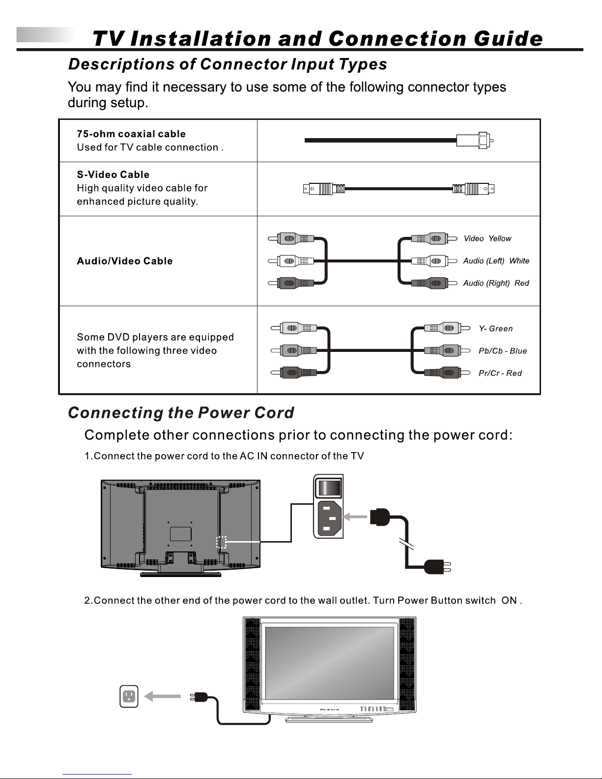
Descriptions of Connector Input Types
Connecting the TV power cord
Adjusting the TV Viewing Angle
Installation
Connecting to an Antenna or Video Equipment with Antenna outlet
Connecting to a VCR
Connecting to a DVD player with A/V or S-Video Cables
Connecting to a DVD player with Component Cables
Connecting to a Satellite Receiver or Cable Box with A/V Cables
Connecting to a Satellite Receiver or Cable Box with Component Connectors
Connecting to a PC with VGA Connector / Other Connections
Remote Control Guide
Key Function and Descriptions
Hotkeys Tutorial
Adjusting the On Screen Display (OSD)
Introduction: To Operate in the OSD
Adjusting Picture Quality
To Reset Factory Settings
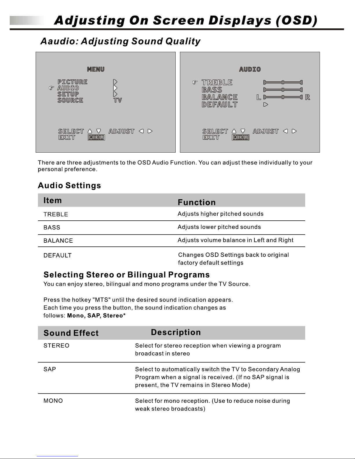
Adjusting Sound Quality
To Select Stereo or Bilingual Programs
Adjusting Personal TV Settings
Setting the Channels
Editing the Channels: Add/Delete Channels
Channel Source
Closed Caption
Parental Control
Sleep
Languages
Adjusting TV Source
Adjusting TV Source under PC (VGA) Mode
Screen Adjustments
Picture Adjustments
Audio Adjustments
OSD Adjustments
Troubleshooting
Specifications
Timing Mode for VGA
Pixels Policy
01
02
05
06
08
10
12
12
13
14
15
16
17
18
19
20
21
22
24
25
25
26
26
27
28
28
29
29
29
32
32
33
33
33
34
35
35
36
37
38
39

Important Safety Instructions
The lightning flash with arrowhead symbol. Within an equilateral triangle. is intended to alert
the presence of uninsulated "dangerous voltage" within the product's enclosure that may be of
a sufficient magnitude to constitute a risk of electric shock to persons.
The exclamation point within an equilateral triangle. is intended to alert the user to the
presence of important operating and maintenance (servicing) instructions in the literature
accompanying the appliance.
To reduce the risk of electronic shock, do not remove cover (or back).
No user-serviceable parts inside.
Refer service to qualified Repair Technician or Repair Center.
01
Risk of electronic shock
Do not open
Caution
Caution
19. WARNING: To prevent injury, this apparatus must be securely attached to the floor/wall in accordance
with the installation instructions.
0
0
0
0
0
0
0
0
0
1. Read these instructions.
2. Keep these instructions.
3. Heed all warnings.
4. Follow all instructions.
5. Do not use this apparatus near water.
6. Clean only with a dry cloth.
. Do not block any ventilation openings. Install in accordance with the manufacturer's instructions.
. Do not install near any heat source such as radiators, heat registers, stoves or other apparatus that
produce heat.
. Do not defeat the safety purpose of the polarized or grounding type plug. A polarized plug has type
blades with one wide than the other. A grounding - type plug has two blades and a third grounding
prong. The wide blade or third prong are provide for your safety.
When the provide plug does not fit into your outlet, consult an electrician for replacement of the
obsolete outlet.
10. Protect the power cord from being walked on or pinched particularly at plugs, convenience
receptacles, and the point where they exit from the apparatus.
11. Only use attachment/accessories specified by the manufacturer.
12. Use only with a cart, stand, tripod, bracket or table specified by the manufacturer,
or sold with the apparatus. When a cart is used, use caution when moving the
cart/apparatus combination to avoid injury from tip-over.
13. Unplug this apparatus during lightning storms or when unused for long periods
of time.
14. Refer all servicing to qualified service personal. Servicing is required when the
apparatus has been damaged in
any way, such as power supply cord or plug is damaged, liquid has been spilled or objects have fallen
into the apparatus, the apparatus has been exposed to rain or moisture, does not operate normally, or
have been dropped.
15. WARNING: To reduce to the risk of fire or electric shock, do not expose this apparatus to rain or moisture.
16. Apparatus shall not be exposed to dripping or splashing and no objects filled with liquids, such as vases,
shall be placed on the apparatus.
17. Unplug the unit and inform the service center in case of abnormalities seen with regards to the operation
of the unit.
18. CAUTION: Danger of explosion if battery is incorrectly replaced. Replace only with the same or
equivalent type.
Caution
These servicing instructions are for use by qualified service personnel only. To reduce the risk of electric
shock, do not perform any servicing other than that contained in the operating instructions unless you are
qualified to do so.
7
8
9


Never insert objects or spill liquid
into the display unit
Never insert any object into the display unit through
openings or spill liquid on the display unit. High
voltage flows in the display unit, and inserting an
object can cause electric shock and/or short internal
parts.
Keep away from water and moisture
Do not place the display in areas where moisture is
present or where the unit may get wet such as bathrooms, kitchen, pool area or in a wet basement.
AC cord protection
The AC cords must be routed properly to prevent
people from stepping on them or objects from resting
on them. Check the cords at the plugs and product.
Keep away from heat sources
Keep the display unit away from heat sources such
as radiators, heaters, stoves and other
heat-generating products.
The liquid crystal panel used in this
product is made of glass
Do not hit the panel. Be careful to prevent from
getting hurt by broken glass pieces in case the panel
breaks.
Follow operating instructions
All operating instructions must be followed.
Precautions when transporting the
display
Carrying the display requires two or more people.
Attachments
Do not use attachments not recommended by the
manufacturer. Use of inadequate attachments may
result in accidents to nearby people or to the unit.
Power source
This product must operate on a power source
specified on the specification label. If you are not
sure of the type of power supply used in your home,
consult your dealer or local power company. For
units designed to operate on batteries or another
power source, refer to the operating instructions.
Overloading
Do not overload AC outlets or extension cords. It
may result in electric shock or start a fire.
Wall mounting
Be sure to install the display unit according to the
method recommended by the manufacturer. Use
only the mounting hardware recommended by the
manufacturer.
Servicing
Do not attempt to service the display unit yourself.
Removing covers expose you to high voltage and
other dangerous conditions. Request a qualified
service technician to perform the service.
Important Safety Precautions
03

Replacement parts
In case the display unit needs replacement parts, make sure that the service technician uses
replacement parts specified by the manufacturer, or those with the same characteristics and
performance as the original parts. Use of unauthorized parts can result in fire, electric shock
and/or other danger.
Safety checks
Upon completion of service or maintenance, request the service technician to perform safety
checks to ensure that the display unit is in proper operating condition.
Repair
When the display unit displays an abnormal condition, any noticeable abnormality in the display
unit indicates that the display unit needs servicing.
If any of the following conditions occurs, unplug the AC cord from the AC outlet, and request a
qualified service person to perform repairs.
1.A liquid was spilled on the display unit or objects have fallen into the display unit.
2.The display unit has been exposed to rain or water.
3.The display unit has been dropped or damaged.
Environment
OO
The display unit only operates within the temperature 0 C to 40 C.Operation outside of the
recommended may cause damage to your product.
Important Safety Precautions
04

Caution
This product satisfies FCC regulations when shielded cables and connectors are used to
connect the unit to other equipment.
Prevent electromagnetic interference from electrical appliances such as radios and televisions.
Please use shielded cables and connectors for connections.
Warning
FCC Regulations state that any unauthorized changes or modifications to this equipment
not expressly approved by the manufacturer could void the user's authority to operate this
equipment.
FCC notice
This equipment has been tested and found to comply with the limits for a Class B digital device,
pursuant to part 15 of the FCC Rules. These limits are designed to provide reasonable protection
against harmful interference in a residential installation. This equipment generates, uses and can
radiate radio frequency energy and, if not installed and used in accordance with the instructions,
may cause harmful interference to radio communications. However, there is no guarantee that
interference will not occur in a particular installation. If this equipment does cause harmful
interference to radio or television reception, which can be determined by turning the equipment off
and on, the user is encouraged to try to correct the interference by one or more of the following
measures:
1.Reorient or relocate the receiving antenna.
2.Increase the separation between the equipment and receiver.
3.Connect the equipment into an outlet on a circuit different from that to which the receiver is
connected.
4.Consult the dealer or an experienced radio/TV technician for help.
Modifications not expressly approved by the manufacturer could void the user's authority to
operated the equipment under FCC rules. This device complies with part 15 of the FCC Rules.
Operation is subject to the following two conditions:
1.This device may not cause harmful interference.
2.This device must accept any interference received, including interference that may cause
undesired operation.
For Canadian model
This Class B digital apparatus complies with Canadian ICES-003.
FCC Statement
Approval
05
LISTED
I.T.E .
E247591
Also Listed
as AV Product

Accessories
Supplied accessories
06
Remote control & batteries (AAA x 2)
Power cord x 1
User manual booklet x 1
LCD Multi-Media Display
LT23HVX
Quick start guide x 1

Accessories
07
Optional accessories
Audio cable with stereo mini jack
Use the proper cable for the device.
Stereo mini jack cable
Stereo mini jack to RCA cable
AV cable with RCA connector
S-Video cable
Audio cable with RCA connector
Wall mount set
Use VESA 100 standard wall monut.
WM15D
VGA cable (D-Sub 15 male) x 1

Wall Mount Kit (Optional)
08
1.Before using wall mount, please read manual of wall mount and following assembly guide.
2.For safety purpose, please purchase wall mount which can bear the LCD TV weight.
3.Following installation instruction is only for your reference.
4.Please consult authorized service personnel for the installation of wall mount.
*Place LCD with facing
downward on flat surface.
Place mounting unit on
the LCD back as figure
and level at holes.
Secure them together
with four screws .And then
tighten them up with
screwdriver(not supplied).
X4
2
X6
*Secure component base firmly to
the solid cement wall with six
expansive bolt.
Note: Please follow the instruction of
removing the STAND before
attaching the WALLMOUNT
on to your LCD TV.

CAUTION
*There are many small components used in the construction of this unit. These loose items
should be kept away from young children while assembling your unit.
*Incomplete or inadequate mounting of this unit to the wall may cause it to fall down, resulting in
potentially fatal accidents.
*Please consult authorized service personnel for the installation of this unit.
120
0.1
O
O
OOO
0
,5
,
1
0,
1
5,
20
307
80
Insert the mounting unit
(with LCD on already) into the
component base and press it down, please
check the angle that user desired then tighten
the knobs as figure above.
Unit : mm
O
20
Wall Mount Kit (Optional)
09

TV Installation and Connection Guide
Identifying Front and Rear Panels
Front Panel
POWER
Turns display On/Off.
MENU
Displays the On Screen Display(OSD) menu. In the OSD menu, press to return to pre-phase .
CH / CH
Adjusts channel programming up or down.
In the OSD menu, both keys are used to navigate within menu.
VOL+ / VOL-
Adjusts volume. In OSD menu, both keys are used to navigate within menu.
VOL+ is used to select the highlighted option.
SOURCE
Press to switch the input sources.
IR SENSOR
Contains Infra-red (IR) light sensor for digital data transmission by the remote control .
Please point remote control at IR Sensor for function.
10
IR Sensor

Rear Panel
TV Installation and Connection Guide
Identifying Front and Rear Panels
NOTE: The S-Video input has a better quality of picture than
a composite Video signal.
11
Power Connections
The power cord connects here.
1
AC In
Headphone
VGA / AV Connections
2
VGA (PC)
Port
The VGA input can be used for analog RGB signals from a
personal computer. VGA has 1 Audio input.
Audio input
The audio input sends the TV's connected audio signals to an
AV receiver or other equipment.
The headphone jack is also located here for audio output.
Service Port
Only for Service Technician use, and do not support any
device for user.
Antenna receives signals from VHF / UHF antennas or a
cable system.
Antenna
(ANT)
These inputs can be used for the connection of A/V equipment
with component video outputs, such as a DVD player, Digital
Satellite Receiver, or compatible Video Game System.
Component
Video
These inputs can be used for the connection of a VCR, Super
VHS (S-VHS) VCR,DVD player, or other video devices to the
TV. There is an S-Video input for video.
AC IN
1
I
o
2
VGA / AV
PC
VIDEO
Component
VGA
Audio In
R
L
Pr/Cr
Pb/Cb
Y
S-Video
ANT
Video
R
L
TV
Service
Port
12
I
o
13

PC
VIDEO
Component
VGA
Audio In
R
L
Pr/Cr
Pb/Cb
Y
S-Video
ANT
Video
L
R
TV
14
PC
VIDEO
Component
VGA
Audio In
R
L
Pr/Cr
Pb/Cb
Y
S-Video
ANT
Video
L
R
TV

15
PC
VIDEO
Component
VGA
Audio In
R
L
Pr/Cr
Pb/Cb
Y
S-Video
ANT
Video
L
R
TV

16
PC
VIDEO
Component
VGA
Audio In
R
L
Pr/Cr
Pb/Cb
Y
S-Video
ANT
Video
L
R
TV

17
PC
VIDEO
Component
VGA
Audio In
L
Pr/Cr
Pb/Cb
Y
R
L

18
PC
VIDEO
Component
VGA
Audio In
R
L
Pr/Cr
Pb/Cb
Y
S-Video
ANT
Video
L
R
TV

19
PC
VIDEO
Component
VGA
Audio In
L
Pr/Cr
Pb/Cb
Y
R
L

20
PC
VGA
Audio In
PC
VGA
Audio In

21
_ _
+
-

22

23

24

25
26

27

28

29

30

31

32

Adjusting On Screen Displays (OSD)
Source: Adjust TV Input Source
You can choose the Input Source of your TV to best display the picture based on your TV connection settings.
Available Input sources: TV, Video1, Video2, Component , PC
There are two ways to choose the Input Source.
1. Choose SOURCE function on the OSD Menu,
and press the key to switch between sources
2. Press the SOURCE hotkey on the remote control.
You can view each source per screen view as noted
on the top upper right hand corner.
3. Direct source screen may also be directly accessed
through the TV, PC (VGA Mode), VIDEO and
COMPONENT hotkeys on the remote control.
PICTUREPICTURE
AUDIOAUDIO
SETUPSETUP
SOURCESOURCE
MENUMENU
COMPONENTCOMPONENT
SCREEN ADJ.SCREEN ADJ.
CLOCK 16CLOCK 16
PHASE 16PHASE 16
H-POS. 16H-POS. 16
V-POS. 16V-POS. 16
DEFAULT NODEFAULT NO
SELECTSELECT ADJUSTADJUST
EXITEXIT
MENUMENU
AUTO NOAUTO NO
33
Adjust TV Source under PC (VGA) MODE
Under the PC (VGA) Source mode, there will be different options for the OSD Settings.
There are four TV Setting to choose from, under the PC Source Mode: Screen, Picture, Audio and OSD
Settings.
Screen
Picture
Audio
OSD
To view each setting, use the and keys.
To make adjustments press the key.
Screen Adjustment
You can adjust the screen display settings
to suit your personal preferences.
AUTO
CLOCK
PHASE
H-POS
V-POS
DEFAULT
Adjust the image to its best position and automatically
displays on the screen
Adjust the pixel clock
Adjust phase
Adjust horizontal display position
Adjust vertical display position
Adjust to original factory default settings
Item
Adjustment
Function
YES / NO
0-31
0-31
0-31
0-31
YES / NO
SELECTSELECT ADJUSTADJUST
EXITEXIT
MENUMENU
1024X768 H60KHZ V75HZ1024X768 H60KHZ V75HZ

Adjusting On Screen Displays (OSD)
Choosing TV Input Source
Picture Adjustment
You can adjust picture display settings to suit your personal preferences.
PICTURE ADJ.PICTURE ADJ.
CONTRAST 10CONTRAST 10
GREEN GAINGREEN GAIN
BLUE GAINBLUE GAIN
SELECTSELECT ADJUSTADJUST
EXITEXIT
MENUMENU
BACKLIGHT BRIGHTBACKLIGHT BRIGHT
Item
Adjustment
Function
BACKLIGHT
CONTRAST
BRIGHTNESS
COLOR TMP.
SOFT/NORMAL/BRIGHT
0-31
0-31
COOL/NORMAL/WARM/USER
Adjusts darkness or lightness of the screen
Adjusts picture color contrast
Adjusts picture brightness contrast
Adjusts image color intensity
Warm: More red-tinted colors
Normal: Standard color temperature
Cool: More blue-tinted colors
Note: Color Temp must be under "USER" in order to manually adjust Red/Green/Blue gain.
The automatic display of the VGA image resolution, horizontal and vertical frequency will
remain flashing intermittently.
34
BRIGHTNESS16BRIGHTNESS16
COLOR TMP.NORMALCOLOR TMP.NORMAL
RED GAINRED GAIN

Adjusting On Screen Displays (OSD)
Choosing TV Input Source
Audio Adjustment
You can adjust audio settings to suit your personal preferences
SELECTSELECT ADJUSTADJUST
EXITEXIT
MENUMENU
PICTURE ADJ.PICTURE ADJ.
VOLUME 31VOLUME 31
MUTE NOMUTE NO
800 600 H37KHZ V60HZ800 600 H37KHZ V60HZ
Item
Adjustment
Function
MUTE
VOLUME
ON / OFF
0-31
Note: The automatic display of the VGA
image resolution, horizontal and
vertical frequency will remain
flashing intermittently.
OSD Adjustment
H-POS
V-POS
DURATION
LANGUAGE
Adjust screen horizontal position
Adjust screen vertical position
Adjust the time of OSD menu display on the screen
English / Spanish / French
Note: The automatic display of the VGA image
resolution, horizontal and vertical frequency
will remain flashing intermittently.
To Exit PC (VGA Mode) Source OSD Menu, press the Menu button.
Item
Adjustment
Function
OSD ADJ.OSD ADJ.
SELECTSELECT ADJUSTADJUST
EXITEXIT
MENUMENU
H-POS. 16
V-POS. 16
DURATION 10
LANGUAGE ENGLISH
H-POS. 16
V-POS. 16
DURATION 10
LANGUAGE ENGLISH
0-31
0-31
3-31
Press to mute the sound
Press to adjust volume
35

Troubleshooting
If you are still experiencing some difficulties with the TV Setup, please refer to the following suggested
solutions for common problems and symptoms.
Power On failed
No picture or sound
Full of spots or noise on the screen
Poor color display
Image distortion
The image is blue
The image is too bright, and the
image is saturated in the brightest
areas.
The screen shows searching for
signal but no image.
Out of range
Remote control does not work
Stripes on the screen
Power plug is not securely inserted into the socket.
1. Check LCD TV power status.
2. Check if the terminal is properly connected and the input mode has a
right connection.
3. Check if the cable is well connected between the video source and
the TV.
Check if any interference from automobiles, trains, high-voltage
transmission lines, neon signs or other potential sources of interference.
Check OSD and adjust in "Picture" function.
Check aspect ratio in "Screen" function.
Check the setting of source in the TV and set it in the right type.
1. Check if the contrast setting is too high.
2. The DVD player is set for a high-level output.
1. Check if the signal cable is disconnected.
2. Check if the terminal is properly connected and the input mode has a
right connection.
Check if input signal is suitable to the display.
1. Check if the batteries are properly installed.
2. Check if the batteries are out of power.
3. Check both distance and angle from the TV's infrared (IR receiver) to
remote control.
4.Check if any object is in between remote control and IR receiver.
5.Check if the IR is under strong fluorescent lighting.
Any antenna from a radio or cell phone may cause interference.
Keep display away from these types of devices.
Problem
Possible Solution
36

Specifications
TFT LCD Panel
VGA Resolution
VGA Input
Vertical Frequency
Horizontal Frequency
TV System
TV Channels
VGA
TV
Support 640 480, 800 600 , 1024 768 & 1280 1024
D-sub 15 pin(3row type) / 3.5mm audio stereo mini phone jack
56Hz ~ 70Hz
31kHz ~ 80kHz
NTSC M
NTSC RF Input, type F connector
MTS, V-Chip & Close Caption.(Optional)
Air and Cable TV
Video Input Format
Video Input
Audio Input
Audio Output
Earphone
Special Features
OSD
IR Remote Control
Power Source
Power Consumption
Dimension (w h d)
Mounting Interface
Weight
Safety / EMI
Accessories
Video / Audio
Others
NTSC-M / PAL / SECAM
Component (Y Pb/Cb Pr/Cr 480i / 576i / 480p / 576p)
R/L 2,(CVB, S-Video) 1, Component 1, PC 1
Speaker R / L 1(5W 2),bass, treble, Balance.
Build-in,Stereo
Wall mount option.
English, Spanish, French
Included
90-240V a.c. 50/60Hz,
130W
27.15" 15.53" 4.20"(w/o stand), 27.15" 16.53" 8.36"(w/stand)
VESA 100
15.44 lbs
UL / CUL / CSA / FCC-B / Energy Star
Remote Control 1, AC power cord 1, User's Manual 1,
Quick start guide 1, Battery 2
37
Screen Size
Aspect Ratio
Resolution
Display Area
Pixel Pitch
Display Color
View Angle(CR>=10)
Response Time
Color Temperature
Dynamic Contrast ratio
(Gray to Gray)
Samsung 23"
16:9
1366X768
508.125mm(H) X 285.696mm(V)
0.372mm(H) X 0.372mm(W)
16.7M Colors
1600:1
178 Hor./ 178 Vert.
8ms
10000 K
LCD Panel
* NOTE : Product Specification is Subject to Change without Notice.

Timing Mode for VGA
Dimensional drawing
38
689.7 mm
348.4mm
381.3 mm
112.1 mm
419.8 mm
102.8 mm
Source
Resolution
Vertical Frequency(Hz)
Note
VGA
640x480
720x400
800x600
800x600
1024x768
1024x768
1280x768
1280x960
1280x1024
60
70
56
60
60
70
60
60
60
VESA
VESA
VESA
VESA
VESA
VESA
VESA
VESA
VESA

Pixels Policy
Syntax's D.O.A. Policy for LCD TVs for
Defective Pixels on LCD Panels
(Applicable to the LCD TV sold within USA & Canada only)
TM
Syntax LCD TVs are evaluated at a distance of approximately 50 centimeters
(approximately 20 inches) between the LCD panel and the eyes of the user at a 90 degrees
viewing angle. All LCD panels have been tested to ensure they comply with our factory standards.
Our evaluation is based on the number of defective pixels and the distance between any two
defective pixels. Bright dots are dots that appear bright and unchanged in size when a LCD TV
screen displays under a black pattern; dark dots are dots that appear dark and unchanged in size
when a LCD TV screen is displayed under pure red, green, or blue patterns ( defective pixels ).
Adjacent dots are dots located directly next to each other.
Customers are required to check their LCD panel immediately after purchase. To identify defective
pixels, the LCD panel should be examined under normal operating conditions as mentioned above,
preferably in its native display resolution, and with a 90 degrees viewing angle.
A LCD TV will be considered dead on arrival (D.O.A.) with regards to defective pixels on the LCD panel
when any one of the following criteria is met:
A total of 7 defective pixels including both bright dots and dark dots are present (the typical
30 LCD Television screen has 16.7 million pixels), or
2 or more pairs of adjacent bright dots are present, or
3 adjacent bright dots are present, or
3 adjacent dark dots are present.
In view of customers' concerns about dead pixels, Syntax would like to address that defective pixels
are not ultimately avoidable with the current LCD industry standard panel manufacturing processes.
We always strive to improve our technology and minimize the chance of occurrence of defective pixels
by applying strict screening processes in our factory production processes. However, Syntax cannot
guarantee that a return unit to our customers will be 100% free of defective pixels.
For questions, please call our toll free service number in the USA at 888-SYNTAX-8.
" At SyntaxGroups, a satisfied customer is our most important focus. "
39
 Loading...