

Synovis GEM FlowCoupler Instructions For Use Manual
1
Instructions for use ..............................................7
Mode d’emploi ...................................................14
Gebrauchsanweisung .........................................21
Istruzioni per l’uso ............................................. 28
Instrucciones de uso ........................................... 35
Gebruiksaanwijzing ...........................................42
Betjeningsvejledning ..........................................49
Bruksanvisning ..................................................56
Kullanım Talimatları ..........................................63
Bruksanvisning ..................................................70
Instruções de utilização ......................................77
Οδηγίες χρήσης ..................................................84
Instrukcja użycia ................................................ 91
GEM
™
Device and System
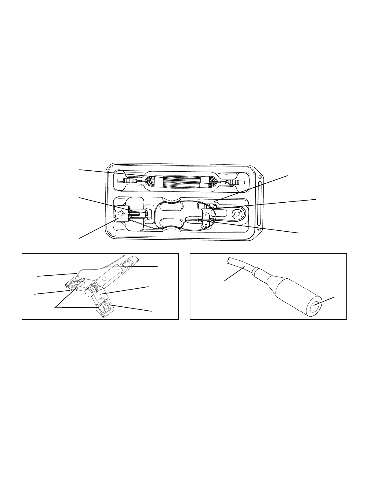
2
FlowCOUPLER Device
External Lead
Probe Connector
Jaw Assembly
Probe Wire
Protective Cover
Suture Sleeve
Probe Wire
Jaw
Probe Wire
Probe
Probe Tip
Jaw Assembly
Probe
Pins
FlowCOUPLER Rings
U Portion of the Jaw
A
B
C
C
D
E
F
G
H
H
M
J
I
F
FK
L

3
A
FlowCOUPLER Device
Dispositif FlowCOUPLER
FlowCOUPLER-Gerät
Dispositivo FlowCOUPLER
Dispositivo FlowCOUPLER
FlowCOUPLER apparaat
FlowCOUPLER enhed
FlowCOUPLER-enhet
FlowCOUPLER Cihazı
FlowCOUPLER-enhet
Dispositivo FlowCOUPLER
Συσκευή FlowCOUPLER
Urządzenie FlowCOUPLER
B
External Lead
Fil externe
Externes Kabel
Elettrocatetere esterno
Conductor eléctrico externo
Externe kabel
Ekstern ledning
Extern ledning
Harici Kablo
Ekstern leder
Condutor Externo
Εξωτερική απαγωγή
Odprowadzenie zewnętrzne
C
Jaw Assembly
Assemblage de la mâchoire
Haltevorrichtung
Gruppo ganasce
Ensamblaje de la mordaza
Klemsamenstel
Kæbemontage
Käftverktyg
Ağız Takımı
Kjevemontering
Conjunto do grampo
Διάταξη σιαγόνων συγκράτησης
Zespół szczęki
D
Protective Cover
Cache de protection
Schutzabdeckung
Copertura di protezione
Tapa protectora
Beschermdeksel
Beskyttelsesafdækning
Skyddshölje
Koruyucu Kapak
Beskyttelsesdeksel
Capa de proteção
Προστατευτικό κάλυμμα
Pokrywa ochronna
E
Probe Connector
Connecteur de la sonde
Messfühleranschluss
Connettore della sonda
Conector de la sonda
Sondeconnector
Sondeforbinder
Sondanslutning
Prob Konektörü
Sondetilkobling
Conector de Sonda
Σύνδεσμος καθετήρα
Złącze sondy
F
Probe Wire
Fil de la sonde
Messfühlerdraht
Filo della sonda
Cable de la sonda
Sondesnoer
Sondeledning
Sondledning
Prob Teli
Sondeleder
Arame de sonda
Σύρμα καθετήρα
Przewód sondy
G
Suture Sleeve
Manchon de suture
Nahthülse
Manicotto di sutura
Camisa de sutura
Hechtkoker
Suturmanchet
Suturring
Sütür Manşonu
Suturmansjett
Manga de Sutura
Θηκάρι συρραφής
Osłona szwu
H
Probe
Sonde
Messfühler
Sonda
Sonda
Sonde
Sonde
Sond
Prob
Sonde
Sonda
Καθετήρας
Sonda
I
Pins
Broches
Nadeln
Perni
Alleres
Pennen
Stifter
Stift
Pinler
Pinner
Pinos
Ακίδες
Szpilki
J
FlowCOUPLER Rings
Anneaux FlowCOUPLER
FlowCOUPLER-Ringe
Anelli FlowCOUPLER
Anillos FlowCOUPLER
FlowCOUPLER ringen
FlowCOUPLER ringe
FlowCOUPLER-ringar
FlowCOUPLER Halkaları
FlowCOUPLER-ringer
anéis FlowCOUPLER
Δακτύλιοι FlowCOUPLER
Pierścienie FlowCOUPLER
K
Jaw
Mâchoire
Backe
Ganascia
Mordaza
Klem
Kæbe
Käft
Ağız
Kjeve
Grampo
Σιαγόνα συγκράτησης
Szczęka
L
U Portion of the Jaw
Segment en U de la mâchoire
U-Bereich der Backe
Porzione a U della ganascia
Porción en forma de U de la mordaza
U-gedeelte van de klem
Kæbens U-formede del
U-formad del av käften
Ağzın U Bölümü
U-del av kjeven
Parte em U do Grampo
Τμήμα δίκην U σιαγόνας συγκράτησης
Część szczęki w kształcie litery U
M
Probe Tip
Extrémité de la sonde
Messfühlerspitze
Punta della sonda
Extremo de la sonda
Sonde-uiteinde
Sondespids
Sondspets
Prob Ucu
Sondespiss
Ponta da Sonda
Άκρο καθετήρα
Końcówka sondy
4
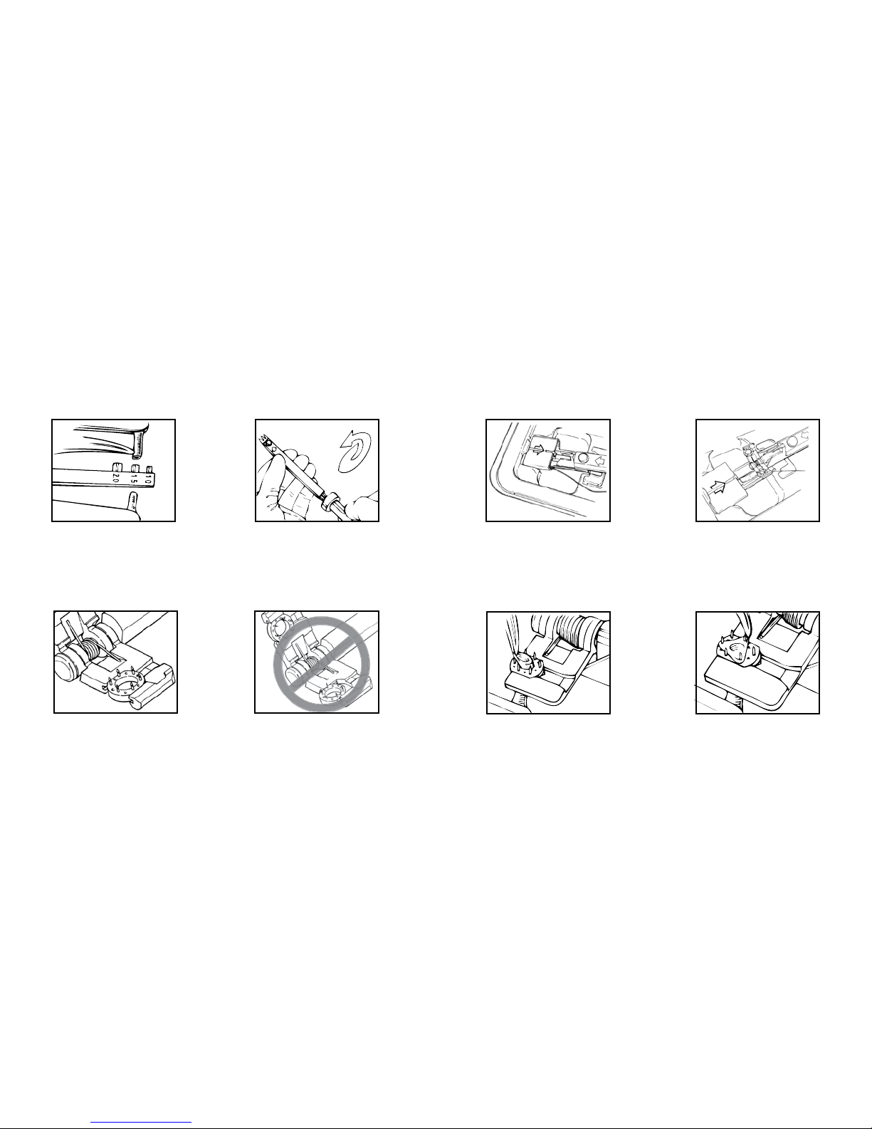
Figure 1 Figure 2 Figure 3 Figure 4
Figure 7Figure 6
Figure 5b
Figure 5a
5
Figure 9
Figure 8
Figure 14Figure 13
Figure 12
Figure 11
Figure 10
6
Figure 20
Figure 19
Figure 16
Figure 18
Figure 17
Figure 15

7
ENGLISH
SYMBOL DEFINITIONS:
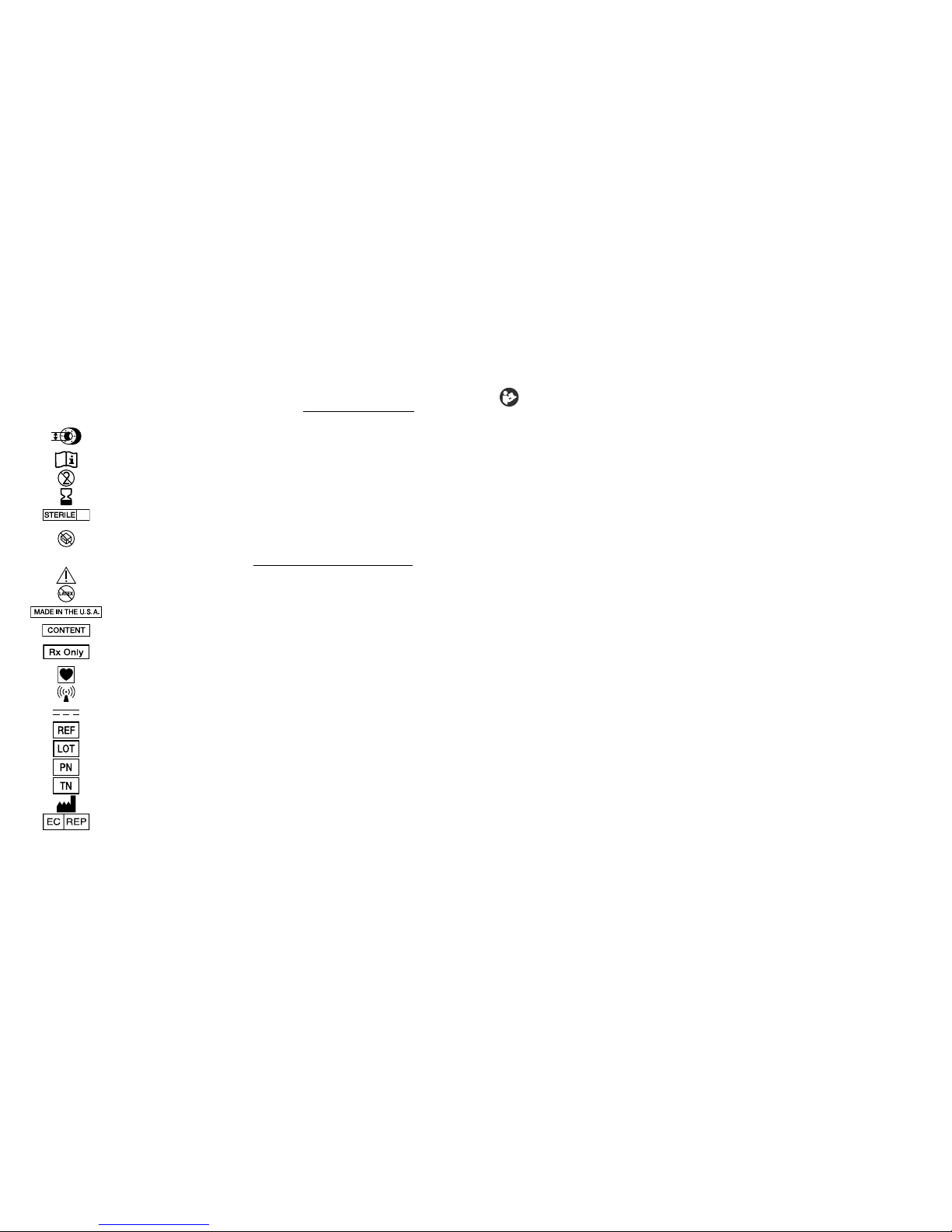
The following symbols and denitions pertain only to the GEM FlowCOUPLER Device:
Size of the GEM FlowCOUPLER Device
(inner diameter of the FlowCOUPLER rings)
Consult instructions for use
Do not reuse
Use by Date
Sterilized using ethylene oxide
Do not use if the product sterilization barrier or its packaging is compromised.
The following symbols and denitions pertain to the GEM FlowCOUPLER Device and System:
Attention, consult accompanying documents.
This product and package is not made with natural rubber latex.
Made in the U.S.A.
Content
CAUTION: Federal (USA) Law restricts this device to sale by or on the order
of a physician.
Type CF Applied Part
RF Transmitter
Direct current
Catalog number
Lot number
Part number
Tracking number
Manufacturer
Authorized Representative in the European Community
Refer to instruction booklet (symbol white on blue)
DESCRIPTION:
The Synovis MCA GEM
TM
FlowCOUPLER® Device and System have been specically
designed for use in end-to-end anastomosis of blood vessels and the detection of blood ow at
the anastomotic site. On an as needed basis, blood ow can be detected for up to 7 days.
The FlowCOUPLER System consists of a FlowCOUPLER Device and a FlowCOUPLER
Monitor. The FlowCOUPLER Device includes a 20MHz ultrasonic Doppler transducer (probe)
attached to one of the FlowCOUPLER rings, and an external lead. The FlowCOUPLER rings
are made of high density polyethylene and surgical grade stainless steel pins. A protective cover
and jaw assembly protect the rings and probe which allow for easy loading onto the Anastomotic
Instrument. Both the protective cover and jaw assembly are disposable.
Accessories to the FlowCOUPLER System include a reusable Anastomotic Instrument (surgical-
grade stainless steel and titanium), a reusable Vessel Measuring Gauge (surgical-grade stainless
steel), COUPLER Forceps (surgical-grade stainless steel), and a Sterilization Tray (anodized
aluminum).
INDICATIONS FOR USE:
The FlowCOUPLER Device is a single use, implantable device that is intended to be used in the
end-to-end anastomosis of veins and arteries normally encountered in microsurgical and vascular
reconstructive procedures. The FlowCOUPLER Device includes a pair of permanently implanted
rings which secure the anastomosis and a removable Doppler probe that is press-t onto one of
the rings. When the FlowCOUPLER Device is used in conjunction with the FlowCOUPLER
Monitor, the FlowCOUPLER System is intended to detect blood ow and conrm vessel patency
intra-operatively and post-operatively at the anastomotic site. Post-operatively, blood ow can
be detected on an as needed basis for up to 7 days. The FlowCOUPLER Doppler probe is not
intended to be a permanent implant and should be removed 3 to 14 days post-operatively.
CONTRAINDICATIONS:
The FlowCOUPLER is not indicated for use in end-to-side anastomosis or for patients presenting
conditions that would normally preclude microvascular repair with suture technique. Examples of
such conditions include, but are not limited to:
• Pre-existing or suspected peripheral vascular disease,
• Ongoing irradiation of the area of reconstruction,
• Clinical infection of the area of reconstruction,
• Anticipated infection due to signicant contamination of the area of reconstruction,
• Friability of the vascular tissue due to sclerotic conditions,
• Concurrent diabetes mellitus, or
• Concurrent corticosteroid therapy
The FlowCOUPLER Device and System is contraindicated for use in the central circulatory
system.
EO

8
WARNINGS:
• Failure to use the Vessel Measuring Gauge to approximate the vessel size could result in using
a FlowCOUPLER of an inappropriate size. Using a ring too large for the vessel may result in
stressing or tearing of the vessel wall and a compromised anastomosis. Using a ring too small
for the vessel may unduly constrict the vessel and lead to thrombosis or ring separation.
• Failure to squeeze the FlowCOUPLER jaws with a hemostat or similar instrument prior
to ejection of the joined rings may result in an inadequate friction t and possible ring
separation. Inspect the anastomotic site to ensure that the anastomosis has been satisfactorily
completed.
• The FlowCOUPLER is supplied sterile and is single use only. Do not resterilize or reuse the
FlowCOUPLER.
- Resterilization may compromise the structural integrity of the product which may lead to
incomplete anastomosis.
- Device cannot be reused due to possible structural damage during rst use which may lead to
incomplete anastomosis.
• Do not use the FlowCOUPLER Device if the package has been opened or appears to be
damaged or compromised as sterility may be compromised. Failure to observe this warning
may result in surgical infection.
• Safe use of the FlowCOUPLER for the anastomosis of tubular structures other than veins and
arteries has not been established.
• Safe use of the FlowCOUPLER for the anastomosis of growing vessels in children or
adolescents has not been established. Not intended for fetal use.
• Safe use of the probe portion of the FlowCOUPLER during MRI procedures has not been
established. Therefore the probe should be removed prior to a MRI procedure.
• Security of an anastomosis utilizing FlowCOUPLERs that have been approximated, reopened,
and then reapproximated has not been demonstrated. When reapproximation of the anastomosis
is desired, the vessel should be removed from each ring and a new FlowCOUPLER utilized.
• Ensure that suture sleeve and connectors are not implanted.
• The Anastomotic Instrument, Vessel Measuring Gauge, COUPLER Forceps, and Sterilization
Tray must be sterilized prior to use.
• The Anastomotic Instrument, Vessel Measuring Gauge, COUPLER Forceps, and Sterilization
Tray should be thoroughly inspected before use. Instruments that are damaged and/or in need
of repair should not be used.
CAUTIONS:
• Use of the FlowCOUPLER involves potential risks normally associated with any implanted
device, e.g., infection, perforation, or laceration of vessels, erosion, implant rejection, or device
dislodgement/migration.
• The angle of the probe wire relative to the ap will be inuenced by the orientation of the
Anastomotic Instrument during formation of the anastomosis. To avoid unwanted kinking or
twisting of the vessel during positioning of the ap-which may result in poor ap perfusioncare should be taken to establish the desired angle of the probe wire relative to the ap and
to adjust the Anastomotic Instrument accordingly prior to starting the anastomosis.
• Should a probe be prematurely removed from the probe-holder, do not attempt to re-insert
the probe into the probe-holder. Instead remove rings and implant a new FlowCOUPLER
Device.
• Probe wire is delicate. The use of crushing forceps may damage the probe wire.
• Use caution when manipulating the probe wire. Sharp bends may cause damage to the
probe wire.
• The use of clamps on the external lead wire may damage the external lead.
• The probe is not intended to be a permanent implant and should be removed 3 to 14 days postoperatively.
• Avoid excessive force to remove the probe from the patient, which may cause injury to the
blood vessel. If the probe can not be removed using gentle traction, the probe should be
surgically removed. Do not cut the probe wire.
• Assure that the probe is attached to the probe wire upon removal of the probe. If not, surgical
removal of the probe is required.
• The FlowCOUPLER should only be used with the GEM FlowCOUPLER Monitor.
• During the use of all ultrasound devices, the operator should minimize the exposure of
ultrasound energy to the patient using the principle of ALARA (As Low As Reasonably
Achievable).
INSTRUCTIONS FOR USE:
These Instructions for Use are designed for proper use of this device. They are not intended to
serve as a reference to surgical technique, to supersede institutional protocols or professional
clinical judgment regarding patient care.
It is the responsibility of the clinician to inform the patient that he/she is the recipient of
permanent implants which contain metal components (surgical-grade stainless steel pins).
The FlowCOUPLERs have been evaluated with a 1.5 Tesla magnetic eld and no change
in displacement was observed in each of three orthogonal planes.¹ The stainless steel pins
in the FlowCOUPLERs are nominally nonferromagnetic. However, the US Food and Drug
Administration (FDA) has made recommendations for any medical device implanted which have
metallic components to include:
• Documentation in the ofcial medical record of the identity of the implant (manufacturer,
model number, lot and serial numbers, and identifying marks, if any).

9
ENGLISH
• Documentation of the technique and results of any magnetic testing performed on the implant
or that no such testing was done.
• Patient education regarding the particular implant and recommendation for identifying medical
alert card, bracelet, or necklace characterizing the implanted device.²
3.0MM COUPLER SIZE OR SMALLER:
END-TO-END ANASTOMOSIS:
Using conventional microsurgical technique, mobilize a minimum of 1 cm of each vessel
end. Using vascular clamps, clamp off the vessel(s) and irrigate the vessel openings. The
FlowCOUPLER requires a greater amount of free vessel within the clamps than a conventional
suture repair.
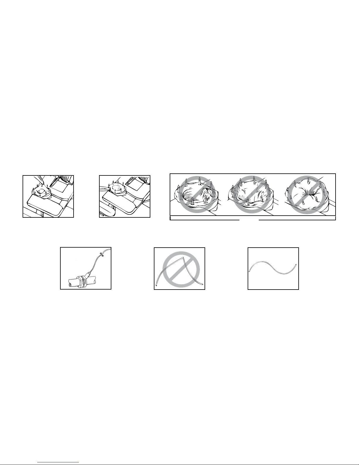
1. After gentle dilation, estimate the outer diameter of each vessel using the Vessel Measuring
Gauge. The circular guides on the gauge should not be placed inside the vessel lumen (See
Figure 1). If there is a size discrepancy between the two vessels, use the measurement of the
smaller vessel to choose the appropriate FlowCOUPLER. The degree of vessel spasm and the
elasticity of the vessel should be considered when choosing the FlowCOUPLER size to be
used.
2. Select the appropriate size FlowCOUPLER. Both vessel ends should be approximately the
same size as the inside diameter of the FlowCOUPLER being selected.
3. Remove the lid from the outer tray and aseptically remove the inner tray; the inner tray may
be placed in the sterile eld. Inspect the inner tray. Do not use if the inner tray is damaged or
if the seals are not intact. Remove the lid from the inner tray.
4. Turn the Anastomotic Instrument knob fully counterclockwise, and then insert the
FlowCOUPLER onto the Anastomotic Instrument while FlowCOUPLER is still in tray. The
matching indicator arrows on the FlowCOUPLER and the Anastomotic Instrument
should be pointing toward each other when loading (See Figures 2 & 3). Ensure that an
audible click is heard for proper loading.
5. Remove FlowCOUPLER from tray and protective cover, being careful not to pull the wire
(See Figure 4).
6. Verify probe function by connecting probe to Monitor and irrigating attached probe tip with
sterile saline. (Refer to the Flow Detection section of these Instructions for Use for proper
connection instructions.) An audible signal from the Monitor veries proper function of the
device. If no signal is identied, refer to the Troubleshooting section of these Instructions for
Use.
7. Visually inspect to see that both rings are seated at the bottom of the U portion of the jaw
(See Figures 5a & 5b) and the pins are not bent. If pins are bent, do not attempt to straighten.
Instead use a new FlowCOUPLER Device.
NOTE: To avoid unwanted kinking or twisting of the vessel during positioning of the ap, care
should be taken to establish the desired angle of the probe wire relative to the ap and to adjust
the Anastomotic Instrument accordingly prior to starting the anastomosis.
8. Place the Anastomotic Instrument perpendicular to the vessel(s), with the FlowCOUPLER
jaw assembly near the two vessel ends. Pull one vessel end through one of the
FlowCOUPLER rings using microsurgical forceps (See Figure 6). Care should be taken
to avoid twisting of the vessel.
9. Take a bite of approximately one to two pin diameters of the vessel wall and intimal lining,
evert 90 degrees and impale onto one pin. Proceeding in a triangular fashion, impale the
vessel rmly upon every other pin, completing three pins (See Figure 7). Complete vessel
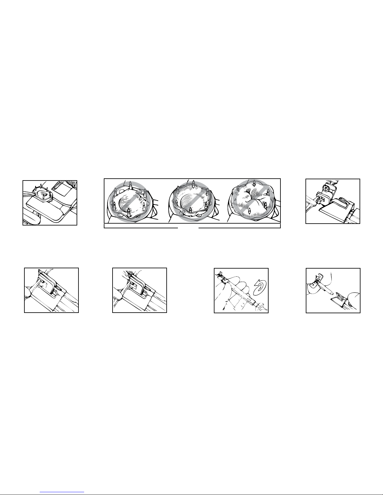
placement on the ring by impaling the vessel upon the remaining three intermediate pins (See
Figure 8). Ensure that both the vessel wall and the intimal layer are fully impaled upon each
pin to reduce the risk of thrombosis. Should the vessel wall tear during impalement, remove
the vessel, trim the end, and repeat the procedure. For examples of improper impalement of
the vessel (See Figure 9).
10. Repeat Steps 8 and 9 to impale the other vessel end upon the second FlowCOUPLER ring.
11. When both vessel ends have been suitably impaled, visually inspect to ensure that both
rings are seated at the bottom of the U portion of the jaw (See Figures 5a & 5b) and the pins
are not bent. Bring the rings together (See Figures 10 & 11) by turning the Anastomotic
Instrument knob clockwise.
12. Prior to ejecting the joined rings, gently squeeze the end of the apposed jaws with a
small hemostat (See Figure 12) to ensure ring approximation and a tight friction t. Turn
the Anastomotic Instrument knob further clockwise to eject the joined rings.
13. Check the anastomosis under the operating microscope before opening the vascular clamps.
Remove the clamps and inspect the anastomotic site to ensure that the anastomosis has
been satisfactorily completed (patent vessel without leakage).
14. To remove the jaw assembly turn the Anastomotic Instrument knob fully counterclockwise
(See Figure 13). Press the release button, located near the arrow on the Anastomotic
Instrument, and remove the jaw assembly (See Figure 14).
15. Rinse the Anastomotic Instrument with water after use.

10
3.5MM COUPLER SIZE OR LARGER:
END-TO-END ANASTOMOSIS:
1. to 8. Follow the same directions as for 3.0mm FlowCOUPLER Size or Smaller End-to-End
Anastomosis (Steps 1 through 8).
9. Take a bite of approximately one to two pin diameters of the vessel wall and intimal lining,
evert 90 degrees and impale onto the pin situated nearest to the open part of the Jaw
Assembly (open end of the U portion of the jaw). Impale the opposite side of the vessel
opening to the pin directly across from the initial pin. Next, impale the vessel onto the pins
located near the sides of the ring, keeping the vessel as evenly spaced as possible between the
four pins (See Figure 15). Continue vessel placement on the ring by impaling the vessel onto
the two remaining pins near the open end of the Jaw Assembly. Complete by impaling the
vessel onto the last two pins near the bottom of the Jaw Assembly (bottom of the U portion
of the jaw); this nal step prevents the ring from sliding out of the Jaw Assembly prematurely
(See Figure 16). Ensure that both the vessel wall and the intimal lining are fully impaled upon
each pin to reduce the risk of thrombosis. Should the vessel wall tear during impalement,
remove the vessel, trim the end, and repeat the procedure. For examples of improper
impalement of the vessel see Figure 17.
10. Repeat Step 9 to impale the other vessel end upon the second FlowCOUPLER ring.
11 to 15. Follow the same directions as for 3.0mm FlowCOUPLER Size or Smaller End-to-End
Anastomosis (Steps 11 through 15).
FLOW DETECTION:
Prior to closure of the surgical site verify detection of blood ow.
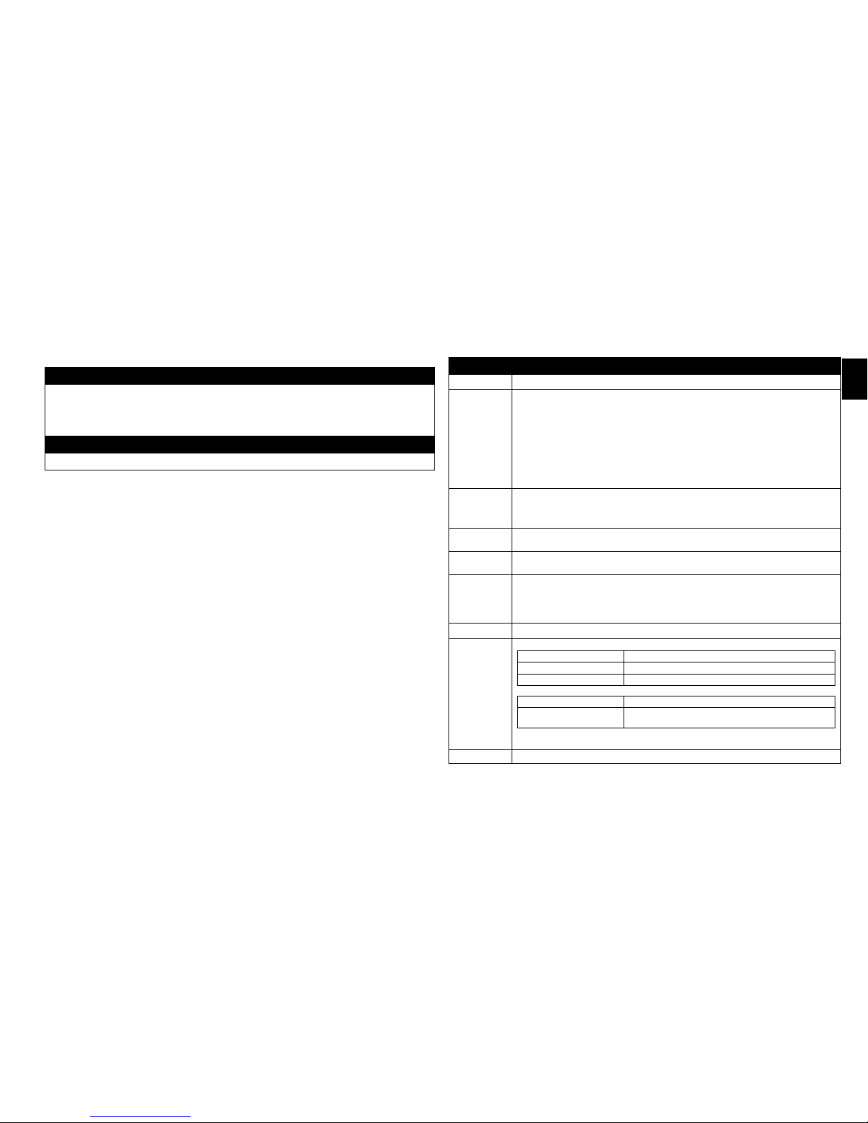
1. Temporarily secure the probe wire to the skin to prevent the weight of the metal connectors
from pulling on the probe.
2. Join the probe connector to either end of the external lead. Attach the other end of the
external lead to the FlowCOUPLER Monitor.
3. Turn on the FlowCOUPLER Monitor.
NOTE: The FlowCOUPLER Monitor can be powered by batteries (8 AA) or with the external
power supply. If the low battery light illuminates, either replace all 8 batteries or use power
supply.
NOTE: For further instructions, refer to the GEM FlowCOUPLER Monitor Instructions for Use.
4. Select appropriate channel on FlowCOUPLER Monitor and listen for blood ow. Adjust
volume as needed. If a strong audible signal is not identied, irrigate the site where the probe
tip meets the vessel with saline. During irrigation, an audible signal from the monitor veries
proper function of the device.
NOTE: Do not attempt to adjust probe location.
5. When routing wire away from the anastomotic site, a loose suture may be placed around
the wire to ensure that it does not affect the orientation of the joined FlowCOUPLER rings.
Optimal wire position would be aligned with probe tip (See Figure 18). Do not bend probe
wire at a sharp angle. (see Figure 19) See Figure 20 for an example of proper probe wire
angle. Carefully position the probe wire to leave enough wire length in the wound, providing
slack to assure there is no tension on the anastomosis.
6. Once satised with wire placement, use a tack suture on the probe wire at the wound margin
(5-0 or similar). Secure the suture sleeve to the skin (suture, tape or staple). Ensure adequate
slack in the wire.
7. Following verication of probe function and wire placement, close the incision using
standard techniques. Cover exposed probe wire with medical dressing.
8. On an as needed basis, blood ow can be detected for up to 7 days. The probe is not
intended to be a permanent implant and should be removed 3 to 14 days post-operatively.
9. When monitor is not being used to detect ow, external lead may be disconnected from the
probe by pulling probe connectors apart.
NOTE: Ischemia or reperfusion rate may delay or affect the initial Doppler signal.
NOTE: If blood ow is not detected with the Monitor post-operatively, rely on clinical
indications for patient status.
NOTE: Doppler signal may vary during monitoring period.
10. To remove the probe, rst detach the suture sleeve and wire from the skin (remove suture,
tape or staple). Remove the probe by applying gentle traction to the wire while applying
counter pressure externally at the site of incision until the probe is extracted. Inspect to ensure
that probe tip is fully intact. If probe is not present, surgical removal is required.
Devices: Anastomotic Instrument, Vessel Measuring Gauge, COUPLER Forceps, and
Sterilization Tray.
11
ENGLISH
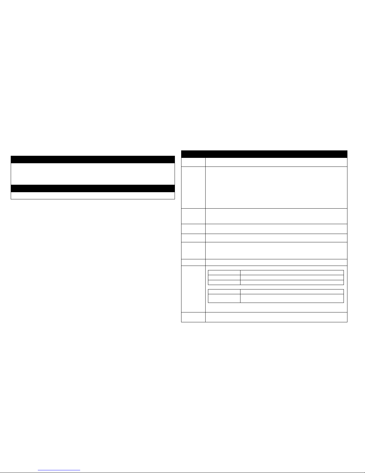
SPECIAL INSTRUCTIONS
WARNINGS
• The Anastomotic Instrument, Vessel Measuring Gauge, COUPLER Forceps, and Sterilization Tray are
supplied non-sterile and must be sterilized prior to use
• The Anastomotic Instrument, Vessel Measuring Gauge, COUPLER Forceps, and Sterilization Tray should
be thoroughly inspected before use. Instruments that are damaged and/or in need of repair should not be
used.
LIMITATIONS ON REPROCESSING
No particular limitations
INSTRUCTIONS
Point of use: Rinse all instruments with water after use.
Preparation
for cleaning:
Cleaning:
Automated
1. Using a neutral (pH 7-10) detergent, wash each tool clean of all blood and debris after
every use. Scrub each tool with a soft brush. Pay particular attention to areas where
debris can accumulate.
CAUTION: Use of a cleaner with a pH greater than 10 will remove the anodized layer of
the Anastomotic Instrument and the Sterilization Tray.
2. Avoid use of any harsh material that can scratch or mar the surface of the instruments
3. Rinse the instruments thoroughly with running water. Apply a ne jet stream through the
hole in the Anastomotic Instrument knob end and press the release button while rinsing
to ensure that all surfaces of the instrument are cleaned.
Using an automated washing machine, clean at a temperature of 45º – 55º C, with a neutral
(pH 7-10) cleaning solution for at least 10 minutes.
Cleaning:
Manual
Place the instruments in an ultrasonic cleaner utilizing a neutral (pH 7-10) cleaning solution
and clean ultrasonically for 15 minutes. Rinse the Anastomotic Instrument thoroughly again,
applying a ne jet stream of water through the hole in the Anastomotic Instrument knob
end.
Disinfection: (Optional) Using an automated washing machine, thermally disinfect the Instrument at a
temperature of 90º - 95º C, for a minimum of 5 minutes.
Drying: Following cleaning by either manual or automated cleaning methods ensure instruments are
fully dry. Do not exceed 100º C for 30 minutes.
Maintenance,
Inspection and
Testing:
• Ensure that all visible debris is removed to assure the continued quality of the
instruments.
• Lubricate the cleaned Anastomotic Instrument (including knob) with a water-soluble
lubricant prior to sterilization. Failure to clean and lubricate the Anastomotic Instrument
as directed may result in instrument failure.
Packaging: Package the instruments using the appropriate method for the sterilization cycle chosen.
Sterilization: GRAVITY AUTOCLAVES
Temperature Recommended Exposure Time (not Total Cycle Time)
250°F (121°C) 15 minutes (wrapped or nonwrapped)
270°F (132°C) 3 minutes (nonwrapped)/10 minutes (wrapped)
PREVAC AUTOCLAVES
Temperature Recommended Exposure Time (not Total Cycle Time)
270°F -273°F
(132°C - 134°C)
3-5 minutes (nonwrapped)
4-5 minutes (wrapped)
NOTE: It is recommended that each institution establish the efcacy of its sterilization
procedure.
Storage Recommended storage at controlled room temperature 20-25°C (68-77°F).

12
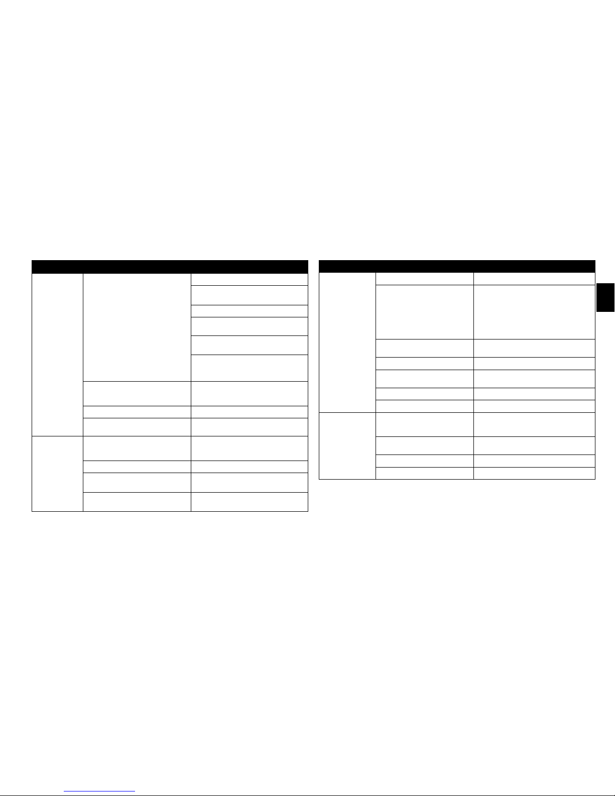
PROBE TROUBLESHOOTING GUIDE
SYMPTOMS POSSIBLE PROBLEMS SOLUTION
No sound output
Intra-operatively
No moisture contact Site irrigation
Verify no vessel stricture
Check blood ow (vein and artery)
Massage blood vessel to increase blood
pressure
Wait until blood ow can be seen and heard
Ischemia or reperfusion rate may delay or
affect the initial Doppler signal. Check with
hand held probe.
No power Check all connections:
• Probe Connector to External Lead
• External Lead to Monitor
External Lead is not functioning Replace External Lead
Probe is not functioning Rely on clinical indications for patient
status.
No sound output
Post-operatively
No power Check all connections:
• Probe Connector to External Lead
• External Lead to Monitor
External Lead is not functioning Replace External Lead
Probe may have lost contact with vessel Rely on clinical indications for patient
status.
Probe is not functioning Rely on clinical indications for patient
status.
MONITOR TROUBLESHOOTING GUIDE
SYMPTOMS POSSIBLE PROBLEM SOLUTION
No sound output No power Verify Monitor power is on
No power Check all connections:
• Probe Connector to External Lead
• External Lead to Monitor
• Monitor to AC Power Supply
• AC Power Supply to Power Cord
• Power Cord to outlet
Volume is too low Adjust volume using Volume Increase switch
Wrong channel is being used Verify the correct channel is illuminated
Batteries are dead Replace batteries or use external power supply
Monitor not functioning Connect a different Monitor
Monitor not functioning Contact Synovis Micro Companies Alliance
Weak sound output Weak batteries
(low battery indicator is illuminated)
Replace batteries or use external power supply
Volume is too low Adjust volume using Volume Increase switch
Monitor not functioning Connect a different Monitor
Monitor not functioning Contact Synovis Micro Companies Alliance

13
ENGLISH
SERVICE:
For Customer or Technical service, contact:
Phone: + 205.941.0111 or 1.800.510.3318
Fax: + 205.941.1522
Website: synovismicro.com
DISCLAIMER OF WARRANTIES:
Synovis Micro Companies Alliance, Inc., (SMCA), a subsidiary of Synovis Life Technologies,
Inc., warrants that reasonable care has been used in the manufacture of this device. This warranty
is exclusive and in lieu of all other warranties whether expressed, implied, written or oral,
including,but not limited to, any implied warranties of merchantability or tness. Since SMCA
has no control over the conditions under which the device is used, diagnosis of the patient,
methods of administration or its handling after it leaves its possession, SMCA does not warrant
either a good effect or against an ill effect following its use. The manufacturer shall not be liable
for any incidental or consequential loss, damage or expense arising directly or indirectly from the
use of this device. SMCA will replace any device which is defective at the time of shipment. No
representative of SMCA may change any of the foregoing or assume any additional liability or
responsibility in connection with this device
REFERENCES:
1. DeLacure M and Wang H: Magnetic Resonance Imaging Assessment of a Microvascular
Anastomotic Device for Ferromagnetism. Journal of Reconstructive Microsurgery 13:8, 1997.
2. Caution needed when performing MRI scans on patients with aneurysm clips. FDA Medical
Bulletin Volume 23, Number 2, June 1993.
14
DÉFINITIONS DES SYMBOLES :
Les symboles et dénitions suivants se rapportent uniquement au dispositif FlowCOUPLER de
GEM :
Taille du dispositif FlowCOUPLER de GEM
(diamètre interne des anneaux FlowCOUPLER)
Consulter le mode d’emploi
Ne pas réutiliser
À utiliser avant le
Stérilisé à l’oxyde d’éthylène
À ne pas utiliser si la barrière de stérilisation du produit ou son emballage sont
compromis.
Les symboles et dénitions suivants se rapportent au dispositif et système FlowCOUPLER de GEM :
Attention, consulter les documents d’accompagnement.
Ce produit et son emballage ne sont pas conçus en latex de caoutchouc naturel.
Fabriqué aux États-Unis
Contenu
MISES EN GARDE : les lois fédérales (U.S.A.) limitent la vente de cet
appareil par ou sur l’ordonnance d’un médecin.
Partie appliquée de type CF
Émetteur RF
Courant continu
Numéro de catalogue
Numéro de lot
Référence
Numéro de traçabilité
Fabricant
Représentant agréé dans la Communauté Européenne
Se référer au livret d’instructions (symbole blanc sur bleu)
DESCRIPTION :
Le dispositif et le système FlowCOUPLER® de Synovis MCA GEMTM ont été spécialement conçus pour
être utilisés lors d’une anastomose bout à bout des vaisseaux sanguins et pour détecter le débit sanguin au
site anastomotique. En fonction des besoins, le débit sanguin peut être détecté pendant 7 jours au maximum.
Le système FlowCOUPLER est constitué d’un dispositif FlowCOUPLER et d’un moniteur
FlowCOUPLER. Le dispositif FlowCOUPLER comprend un l externe et un transducteur Doppler à
ultrasons de 20 MHz (la sonde) xé à l’un des anneaux FlowCOUPLER. Les anneaux FlowCOUPLER
sont fabriqués à partir de polyéthylène haute densité et de broches en acier inoxydable de classe
chirurgicale. Un cache de protection et un assemblage de mâchoire protègent les anneaux et la sonde, ce
qui facilite l’emboîtement sur l’instrument anastomotique. Le cache de protection et l’assemblage de la
mâchoire sont à usage unique.
Les accessoires du système FlowCOUPLER comprennent un instrument anastomotique réutilisable (en
titane et acier inoxydable de classe chirurgicale), un outil de mesure des vaisseaux réutilisable (en acier
inoxydable de classe chirurgicale), une pince COUPLER (en acier inoxydable de classe chirurgicale) et un
plateau de stérilisation (en aluminium anodisé).
INDICATIONS D’UTILISATION :
FlowCOUPLER est un dispositif implantable à usage unique conçu pour être utilisé lors d’une anastomose
bout à bout des veines et des artères qui a lieu, en général, dans le cadre d’interventions microchirurgicales
et de reconstruction vasculaire. Le dispositif FlowCOUPLER se compose d’une paire d’anneaux implantés
dénitivement qui sécurisent l’anastomose et d’une sonde Doppler amovible emboutie sur l’un des
anneaux. Lorsque le dispositif FlowCOUPLER et le moniteur FlowCOUPLER sont utilisés ensemble,
le système FlowCOUPLER a pour but de détecter le débit sanguin et de conrmer la perméabilité
des vaisseaux pendant et après une intervention sur le site anastomotique. Après une intervention, le
débit sanguin peut être détecté au besoin pendant 7 jours au maximum. La sonde Doppler du dispositif
FlowCOUPLER n’est pas destinée à être implantée dénitivement et doit être retirée 3 à 14 jours après
l’intervention.
CONTRE-INDICATIONS :
L’utilisation du dispositif FlowCOUPLER est contre-indiquée dans une anastomose termino-latérale ou
pour des patients présentant des affections qui excluraient normalement une réparation microvasculaire avec
une technique de suture. Parmi ces affections gurent, mais sans s’y limiter :
• une maladie vasculaire périphérique préexistante ou suspectée
• une irradiation en cours de l’aire de reconstruction
• une infection clinique de l’aire de reconstruction
• une infection attendue due à une contamination importante de la zone de reconstruction
• une friabilité du tissu vasculaire due à des conditions sclérotiques
EO

15
FRANÇAIS
• un diabète sucré concomitant ou
• une corticothérapie concomitante.
Le dispositif et le système FlowCOUPLER ne conviennent pas à une utilisation dans le système circulatoire
central.
AVERTISSEMENTS :
• La non-utilisation de l’outil de mesure des vaisseaux pour évaluer la taille du vaisseau pourrait entraîner
l’emploi d’un dispositif FlowCOUPLER de taille inappropriée. L’utilisation d’un anneau trop large
pour le vaisseau pourrait provoquer une tension ou une déchirure de la paroi vasculaire et compromettre
l’anastomose. L’utilisation d’un anneau trop petit pour le vaisseau pourrait comprimer excessivement le
vaisseau et engendrer une thrombose ou une séparation des anneaux.
• Ne pas presser les mâchoires du dispositif FlowCOUPLER avec une pince hémostatique ou un
instrument similaire avant l’éjection des anneaux joints pourrait entraîner un ajustement par friction
inadéquat et une séparation possible des anneaux. Inspecter le site anastomotique pour s’assurer que
l’anastomose a été réalisée de manière satisfaisante.
• Le dispositif FlowCOUPLER est exclusivement à usage unique et fourni stérile. Ne pas restériliser ou
réutiliser le dispositif FlowCOUPLER.
- La restérilisation pourrait compromettre l’intégrité structurelle du produit et entraîner une anastomose
incomplète.
- Le dispositif ne peut pas être réutilisé en raison des dommages structurels possibles survenus lors de la
première utilisation, qui pourraient entraîner une anastomose incomplète.
• Ne pas utiliser le dispositif FlowCOUPLER si l’emballage a été ouvert ou semble endommagé ou
fragilisé, car la stérilité pourrait être compromise. La non-observation de ces avertissements pourrait
entraîner des infections chirurgicales.
• L’utilisation en toute sécurité du dispositif FlowCOUPLER pour l’anastomose de structures tubulaires
autres que les veines et les artères n’a pas été établie.
• L’utilisation en toute sécurité du dispositif FlowCOUPLER pour l’anastomose de vaisseaux en croissance
chez des enfants ou des adolescents n’a pas été établie. Non destiné à une utilisation fœtale.
• L’utilisation en toute sécurité de la partie sonde du dispositif FlowCOUPLER durant des procédures
d’IRM n’a pas été établie. La sonde doit par conséquent être retirée avant une procédure d’IRM.
• La sécurité d’une anastomose réalisée avec un dispositif FlowCOUPLER qui a été rapproché, réouvert
puis rapproché de nouveau n’a pas été démontrée. Lorsqu’un nouveau rapprochement de l’anastomose
est souhaité, le vaisseau doit être retiré de chaque anneau et un nouveau dispositif FlowCOUPLER doit
être utilisé.
• S’assurer que le manchon de suture et les connecteurs ne sont pas implantés.
• L’instrument anastomotique, l’outil de mesure des vaisseaux, la pince COUPLER et le plateau de
stérilisation doivent être stérilisés avant utilisation.
• L’instrument anastomotique, l’outil de mesure des vaisseaux, la pince COUPLER et le plateau de
stérilisation doivent être minutieusement examinés avant utilisation. Les instruments endommagés et/ou
qui nécessitent une réparation ne doivent pas être utilisés.
MISES EN GARDE :
• L’utilisation du dispositif FlowCOUPLER comporte des risques potentiels normalement associés à tout
dispositif implanté, p. ex. infection, perforation ou lacération des vaisseaux, érosion, rejet de l’implant ou
encore déplacement/migration du dispositif.
• L’angle du l de la sonde par rapport au lambeau dépendra de l’orientation de l’instrument
anastomotique pendant la formation de l’anastomose. Pour éviter qu’un vaisseau se torde ou s’enroule
accidentellement durant le placement du lambeau (ce qui pourrait entraîner une mauvaise perfusion du
lambeau), il convient de bien déterminer l’angle souhaité du l de la sonde par rapport au lambeau et
d’ajuster l’instrument anastomotique en conséquence, avant de commencer une anastomose.
• Au cas où une sonde serait prématurément retirée du support de sonde, ne pas tenter de la réinsérer dans
le support. Retirer plutôt les anneaux et implanter un nouveau dispositif FlowCOUPLER.
• Le l de la sonde est fragile. L’utilisation d’une pince pour écrasement pourrait endommager le l
de la sonde.
• Manipuler le l de la sonde avec précaution. Des plis prononcés pourraient endommager le l de
la sonde.
• L’utilisation de clamps sur le l externe pourrait endommager le l externe.
• La sonde n’est pas destinée à être implantée dénitivement et doit être retirée 3 à 14 jours après
l’intervention.
• Éviter de retirer en force la sonde du patient, ce qui pourrait endommager le vaisseau sanguin. Si la sonde
ne peut pas être retirée par une traction légère, elle doit être retirée par chirurgie. Ne pas couper le l de
la sonde.
• Vérier que la sonde est xée sur le l de la sonde au moment de la retirer. Dans le cas contraire, il est
nécessaire de retirer la sonde par chirurgie.
• Le dispositif FlowCOUPLER doit être utilisé uniquement avec le moniteur FlowCOUPLER de GEM.
• Lors de l’utilisation de dispositifs à ultrasons, l’opérateur doit minimiser l’exposition du patient
à l’énergie ultrasonique en appliquant le principe ALARA (« aussi faible que raisonnablement
possible »).
MODE D’EMPLOI :
Le présent mode d’emploi est conçu pour une utilisation correcte de ce dispositif. Il n’est pas destiné à
servir de référence pour une technique chirurgicale ni à supplanter le protocole d’un établissement ou le
jugement clinique d’un professionnel concernant les soins donnés au patient.
Il incombe au clinicien d’informer le patient qu’il/elle va recevoir des implants dénitifs contenant
des composants métalliques (broches en acier inoxydable de classe chirurgicale). Les dispositifs
FlowCOUPLER ont été évalués avec un champ magnétique de 1,5 tesla et aucun changement de

16
déplacement n’a été observé sur les trois plans orthogonaux.¹ Les broches en acier inoxydable contenues
dans les dispositifs FlowCOUPLER ne sont théoriquement pas ferromagnétiques. Toutefois, la FDA
(US Food and Drug Administration) recommande que tout dispositif médical implanté contenant des
composants métalliques contienne :
• une documentation dans le dossier médical ofciel concernant l’identication de l’implant (fabricant,
numéro de modèle, numéros de lot et de série, ainsi que marques d’identication le cas échéant)
• une documentation sur la technique et les résultats de tout test magnétique réalisé sur l’implant ou un
document précisant qu’aucun test de ce type n’a été effectué
• l’éducation du patient à l’implant particulier et aux recommandations pour l’identication d’une carte,
d’un bracelet ou d’un collier d’alerte médicale portant les caractéristiques du dispositif implanté.²
TAILLE DE DISPOSITIF COUPLER 3,0 MM OU INFÉRIEURE :
ANASTOMOSE BOUT À BOUT :
En utilisant une technique de microchirurgie conventionnelle, mobiliser au minimum 1 cm à chaque
extrémité de vaisseau. À l’aide de clamps vasculaires, comprimer le(s) vaisseau(x) et irriguer les ouvertures
de vaisseau. Le dispositif FlowCOUPLER requiert une plus grande longueur de vaisseau libre à l’intérieur
des clamps qu’une réparation par suture conventionnelle.
1. Après une légère dilatation, estimer le diamètre extérieur de chaque vaisseau à l’aide de l’outil
de mesure des vaisseaux. Les aides circulaires de l’outil de mesure ne doivent pas être placées à
l’intérieur de la lumière du vaisseau (voir gure 1). Si les deux vaisseaux sont de taille différente,
utiliser la mesure du vaisseau le plus petit pour choisir le dispositif FlowCOUPLER approprié. Le
degré de spasme vasculaire et l’élasticité du vaisseau doivent être pris en compte lors du choix de la
taille du dispositif FlowCOUPLER.
2. Sélectionner la taille appropriée du dispositif FlowCOUPLER. Les deux extrémités de vaisseau
doivent avoir approximativement la même taille que le diamètre intérieur du dispositif FlowCOUPLER
sélectionné.
3. Ôter le couvercle du plateau extérieur et retirer le plateau intérieur de façon aseptique. Le plateau
intérieur peut être placé dans le champ stérile. Inspecter le plateau intérieur. Ne pas utiliser si le plateau
intérieur est endommagé ou si les parties scellées ne sont pas intactes. Retirer le couvercle du plateau
intérieur.
4. Tourner le bouton de l’instrument anastomotique à fond dans le sens antihoraire ; puis tandis que le
dispositif FlowCOUPLER se trouve toujours sur le plateau, l’insérer sur l’instrument anastomotique.
Les èches indicatrices de correspondance sur le dispositif FlowCOUPLER et sur l’instrument
anastomotique doivent se faire face lors de l’emboîtement (voir gures 2 et 3). S’assurer qu’un clic
sonore est perçu, qui témoigne de l’emboîtement correct.
5. Retirer le dispositif FlowCOUPLER du plateau et du cache de protection en veillant à ne pas tirer sur le
l (voir gure 4).
6. Vérier que la sonde fonctionne en la connectant au moniteur et en irriguant l’extrémité xée de la
sonde avec du sérum physiologique. (Consulter la section Détection du débit dans ce mode d’emploi
pour connaître les instructions de branchement.) Un signal sonore du moniteur permet de vérier le bon
fonctionnement du dispositif. Si aucun signal n’est identié, consulter la section Dépannage dans ce
mode d’emploi.
7. Effectuer une inspection visuelle pour vérier que les deux anneaux sont logés au bas du segment en U
de la mâchoire (voir gures 5a et 5b) et que les broches ne sont pas pliées. Si les broches sont pliées, ne
pas tenter de les redresser. Utiliser plutôt un nouveau dispositif FlowCOUPLER.
REMARQUE : pour éviter qu’un vaisseau se torde ou s’enroule accidentellement durant le positionnement
du lambeau, il convient de bien déterminer l’angle souhaité du l de la sonde par rapport au lambeau et
d’ajuster l’instrument anastomotique en conséquence, avant de commencer une anastomose.
8. Placer l’instrument anastomotique perpendiculairement au(x) vaisseau(x), avec l’assemblage de la
mâchoire du dispositif FlowCOUPLER près des deux extrémités de vaisseau. Tirer une extrémité
de vaisseau à travers l’un des anneaux FlowCOUPLER à l’aide d’une pince microchirurgicale (voir
gure 6). Veiller à ne pas tordre le vaisseau.
9. Pincer un morceau de la paroi et de l’intima du vaisseau représentant approximativement un à deux
diamètres de broche, l’éverser sur 90 degrés et l’empaler sur une broche. En procédant selon un modèle
triangulaire, empaler le vaisseau fermement sur une broche sur deux, utilisant ainsi trois broches
(voir gure 7). Terminer la mise en place sur l’anneau en empalant le vaisseau sur les trois broches
intermédiaires restantes (voir gure 8). S’assurer que la paroi et l’intima du vaisseau sont toutes
deux complètement empalées sur chaque broche an de réduire les risques de thrombose. Si la paroi
vasculaire devait se déchirer durant l’empalement, retirer le vaisseau, couper l’extrémité et répéter la
procédure. Pour des exemples d’empalement incorrect de vaisseau, voir gure 9.
10. Répéter les étapes 8 et 9 pour empaler l’autre extrémité de vaisseau sur le second anneau
FlowCOUPLER.
11. Lorsque les deux extrémités de vaisseau ont été correctement empalées, effectuer une inspection
visuelle pour vérier que les deux anneaux sont logés au fond du segment en U de la mâchoire (voir
gures 5a et 5b) et que les broches ne sont pas pliées. Rapprocher les anneaux (voir gures 10 et 11) en
tournant le bouton de l’instrument anastomotique dans le sens horaire.
12. Avant d’éjecter les anneaux joints, presser doucement l’extrémité des mâchoires accolées à
l’aide d’une petite pince hémostatique (voir gure 12) an d’assurer le rapprochement des
anneaux et d’obtenir un ajustement par friction serré. Tourner davantage le bouton de l’instrument
anastomotique dans le sens horaire pour éjecter les anneaux joints.
13. Vérier l’anastomose au microscope opératoire avant d’ouvrir les clamps vasculaires. Retirer les
clamps et inspecter le site anastomotique an de vérier que l’anastomose a été réalisée de
manière satisfaisante (vaisseau testé sans fuite).

17
FRANÇAIS
14. Pour retirer l’assemblage de la mâchoire, tourner le bouton de l’instrument anastomotique à fond dans
le sens antihoraire (voir gure 13). Appuyer sur le bouton de déblocage situé près de la èche sur
l’instrument anastomotique et retirer l’assemblage de la mâchoire (voir gure 14).
15. Rincer l’instrument anastomotique à l’eau après utilisation.
TAILLE DE DISPOSITIF COUPLER 3,5 MM OU SUPÉRIEURE :
ANASTOMOSE BOUT À BOUT :
1. à 8. Suivre les mêmes instructions que pour l’anastomose bout à bout avec la taille de dispositif
FlowCOUPLER 3,0 mm (étapes 1 à 8).
9. Pincer un morceau de la paroi et de l’intima du vaisseau représentant approximativement un à deux
diamètres de broche, l’éverser sur 90 degrés et l’empaler sur la broche située la plus près de la partie
ouverte de l’assemblage de la mâchoire (extrémité ouverte du segment en U de la mâchoire). Empaler
le côté opposé de l’ouverture du vaisseau sur la broche directement opposée à la broche initiale.
Empaler ensuite le vaisseau sur les broches situées près des côtés de l’anneau, en veillant à ce que le
vaisseau soit réparti le plus uniformément possible entre les quatre broches (voir gure 15). Continuer
la mise en place du vaisseau sur l’anneau en empalant le vaisseau sur les deux broches restantes près
de l’extrémité ouverte de l’assemblage de la mâchoire. Terminer en empalant le vaisseau sur les deux
dernières broches près du fond de l’assemblage de la mâchoire (fond du segment en U de la mâchoire).
Cette étape nale empêche l’anneau de glisser prématurément hors de l’assemblage de la mâchoire
(voir gure 16). S’assurer que la paroi et l’intima du vaisseau sont toutes deux complètement empalées
sur chaque broche an de réduire les risques de thrombose. Si la paroi vasculaire devait se déchirer
durant l’empalement, retirer le vaisseau, couper l’extrémité et répéter la procédure. Pour des exemples
d’empalement incorrect du vaisseau, voir gure 17.
10. Répéter l’étape 9 pour empaler l’autre extrémité de vaisseau sur le second anneau FlowCOUPLER.
11. à 15. Suivre les mêmes instructions que pour l’anastomose bout à bout avec la taille de dispositif
FlowCOUPLER 3,0 mm (étapes 11 à 15).
DÉTECTION DU DÉBIT :
Avant de fermer le site chirurgical, vérier la détection du débit sanguin.
1. Fixer temporairement le l de la sonde sur la peau pour éviter que le poids des connecteurs métalliques
ne tire sur la sonde.
2. Relier le connecteur de la sonde à l’une des extrémités du l externe. Fixer l’autre extrémité du l
externe au moniteur FlowCOUPLER.
3. Mettre le moniteur FlowCOUPLER sous tension.
REMARQUE : le moniteur FlowCOUPLER peut être alimenté par des piles (8 AA) ou par l’alimentation
électrique externe. Si le voyant de pile faible s’allume, remplacer l’ensemble des 8 piles ou utiliser
l’alimentation électrique.
REMARQUE : pour de plus amples instructions, consulter le mode d’emploi du moniteur FlowCOUPLER
de GEM.
4. Sélectionner le canal approprié sur le moniteur FlowCOUPLER et écouter le débit sanguin. Régler le
volume au besoin. Si aucun signal sonore fort n’est identié, irriguer le site à l’endroit où l’extrémité
de la sonde est en contact avec le vaisseau avec du sérum physiologique. Au cours de l’irrigation, un
signal sonore du moniteur permet de vérier le bon fonctionnement du dispositif.
REMARQUE : ne pas tenter d’ajuster l’emplacement de la sonde.
5. Lorsque le l est acheminé à l’écart du site de l’anastomose, une suture lâche peut être placée autour
du l pour s’assurer qu’il ne joue pas sur l’orientation des anneaux FlowCOUPLER joints. La position
optimale est réalisée lorsque le l est aligné avec l’extrémité de la sonde (voir gure 18). Ne pas plier
le l de la sonde en formant un angle prononcé (voir gure 19). La gure 20 montre un exemple de
courbure correcte du l de la sonde. Positionner avec soin le l de la sonde pour laisser sufsamment
de longueur de l dans la plaie et donner du jeu, an qu’il n’y ait aucune tension sur l’anastomose.
6. Lorsque l’emplacement du l est satisfaisant, utiliser une suture avec agrafes sur le l de la sonde au
niveau des berges de la plaie (5-0 ou similaire). Fixer le manchon de suture sur la peau (suture, ruban
ou agrafe). S’assurer que le l a sufsamment de jeu.
7. Après vérication du fonctionnement de la sonde et de l’emplacement du l, fermer l’incision en
utilisant une technique standard. Couvrir le l de la sonde exposé à l’aide d’un pansement.
8. En fonction des besoins, le débit sanguin peut être détecté pendant 7 jours au maximum. La sonde n’est
pas destinée à être implantée dénitivement et doit être retirée 3 à 14 jours après l’intervention.
9. Lorsque le moniteur n’est pas utilisé pour détecter le débit, le l externe peut être déconnecté de la
sonde en retirant les connecteurs de la sonde.
REMARQUE : ll’ischémie ou le débit de reperfusion peut retarder ou affecter le signal Doppler initial.
REMARQUE : si le débit sanguin n’est pas détecté à l’aide du moniteur après l’intervention, se er aux
indications cliniques pour déterminer l’état du patient.
REMARQUE : le signal Doppler peut varier au cours de la période de surveillance.
10. Pour retirer la sonde, détacher d’abord le manchon de suture et le l de la peau (enlever la suture, le
ruban ou l’agrafe). Retirer la sonde en appliquant une légère traction sur le l tout en appliquant une
contre-pression externe au site de l’incision jusqu’à ce que la sonde soit extraite. Inspecter pour vérier
que l’extrémité de la sonde est parfaitement intacte. Si la sonde n’a pas pu être extraite, il est nécessaire
de la retirer par chirurgie.
Dispositifs : instrument anastomotique, outil de mesure des vaisseaux, pince COUPLER et plateau de
stérilisation.
18
INSTRUCTIONS SPÉCIALES
AVERTISSEMENTS
• L’instrument anastomotique, l’outil de mesure des vaisseaux, la pince COUPLER et le plateau de
stérilisation sont fournis non stériles et doivent être stérilisés avant utilisation.
• L’instrument anastomotique, l’outil de mesure des vaisseaux, la pince COUPLER et le plateau de
stérilisation doivent être minutieusement examinés avant utilisation. Les instruments endommagés et/ou qui
nécessitent une réparation ne doivent pas être utilisés.
RESTRICTIONS SUR LE RETRAITEMENT
Aucune restriction particulière
INSTRUCTIONS
Point
d’utilisation :
Rincer tous les instruments à l’eau après utilisation.
Préparation
pour le
nettoyage :
Nettoyage :
automatique
1. À l’aide d’un détergent neutre (pH 7-10), laver chaque outil et retirer toute trace de sang et tout
débris après chaque utilisation. Frotter chaque outil avec une brosse douce. Porter une attention
particulière aux endroits où les débris peuvent s’accumuler.
MISE EN GARDE : l’utilisation d’un nettoyant de pH supérieur à 10 fera disparaitre la couche
anodisée de l’instrument anastomotique et du plateau de stérilisation.
2. Éviter d’utiliser tout matériau dur qui peut rayer ou endommager la surface des instruments.
3. Rincer minutieusement les instruments à l’eau courante. Faire couler un n jet d’eau à travers le
trou situé à l’extrémité du bouton de l’instrument anastomotique, puis appuyer sur le bouton de
déblocage tout en rinçant pour s’assurer que toutes les surfaces de l’instrument sont nettoyées.
Nettoyer à une température comprise entre 45 - 55 °C dans une machine de lavage automatique en
utilisant une solution de nettoyage neutre (pH 7-10) pendant au moins 10 minutes.
Nettoyage :
manuel
Placer les instruments dans un appareil de nettoyage à ultrasons en utilisant une solution de
nettoyage neutre (pH 7-10) et nettoyer par ultrasons pendant 15 minutes. Rincer de nouveau
minutieusement l’instrument anastomotique, en faisant couler un n jet d’eau à travers le trou situé
à l’extrémité du bouton de l’instrument.
Désinfection : (Optionnel) Dans une machine de lavage automatique, désinfecter l’instrument thermiquement à
une température comprise entre 90 - 95 °C pendant au minimum 5 minutes.
Séchage : Après un nettoyage manuel ou automatique, s’assurer que les instruments sont parfaitement secs.
Ne pas dépasser 30 minutes à 100 °C.
Entretien,
inspection et
essai :
• S’assurer que tous les débris visibles sont retirés pour garantir la qualité continue des instruments.
• Lubrier l’instrument anastomotique nettoyé (y compris le bouton) avec un lubriant
hydrosoluble avant la stérilisation. Ne pas nettoyer ni lubrier l’instrument anastomotique selon
les instructions peut entraîner un dysfonctionnement de l’instrument.
Emballage : Emballer les instruments selon la méthode requise pour le cycle de stérilisation choisi.
Stérilisation : AUTOCLAVES À GRAVITÉ
Température Durée d’exposition recommandée (non pas durée totale du cycle)
121 °C (250 °F) 15 minutes (avec ou sans emballage)
132 °C (270 °F) 3 minutes (sans emballage)/10 minutes (avec emballage)
AUTOCLAVES À PRÉ-VIDE
Température Durée d’exposition recommandée (non pas durée totale du cycle)
132 - 134 °C
(270 - 273 °F)
3 - 5 minutes (sans emballage)
4 - 5 minutes (avec emballage)
REMARQUE : il est recommandé que chaque établissement établisse l’efcacité de sa procédure
de stérilisation.
Stockage Il est recommandé de stocker le produit à une température ambiante contrôlée comprise entre
20 - 25 °C (68 - 77 °F).
19
FRANÇAIS
GUIDE DE DÉPANNAGE DE LA SONDE
SYMPTÔMES PROBLÈMES POSSIBLES SOLUTION
Aucune sortie
sonore durant
l’intervention
Aucun contact avec de l’humidité
Irrigation du site
S’assurer qu’il n’y a aucune striction
vasculaire.
Vérier le ux sanguin (veine et artère).
Masser le vaisseau sanguin pour augmenter la
pression sanguine.
Attendre jusqu’à ce que le ux sanguin soit
vu et entendu.
L’ischémie ou le débit de reperfusion peut
retarder ou affecter le signal Doppler initial.
Vérier avec une sonde mobile.
Aucune alimentation
Vérier toutes les connexions :
• du connecteur de la sonde au l externe
• du l externe au moniteur
Le l externe ne fonctionne pas.
Remplacer le l externe.
La sonde ne fonctionne pas.
Se er aux indications cliniques pour
déterminer l’état du patient.
Aucune sortie
sonore après
l’intervention
Aucune alimentation
Vérier toutes les connexions :
• du connecteur de la sonde au l externe
• du l externe au moniteur
Le l externe ne fonctionne pas.
Remplacer le l externe.
La sonde peut ne plus être en contact
avec le vaisseau.
Se er aux indications cliniques pour
déterminer l’état du patient.
La sonde ne fonctionne pas.
Se er aux indications cliniques pour
déterminer l’état du patient.
GUIDE DE DÉPANNAGE DU MONITEUR
SYMPTÔMES PROBLÈME POSSIBLE SOLUTION
Aucune sortie
sonore
Aucune alimentation Vérier que le moniteur est sous tension.
Aucune alimentation Vérier toutes les connexions :
• du connecteur de la sonde au l externe
• du l externe au moniteur
• du moniteur à l’alimentation CA
• de l’alimentation CA au cordon
d’alimentation
• du cordon d’alimentation à la prise
murale
Le volume est trop faible. Régler le volume à l’aide du bouton
d’augmentation du volume.
Un canal incorrect est utilisé. Vérier que le voyant du bon canal est allumé.
Les piles sont épuisées. Remplacer les piles ou utiliser l’alimentation
externe.
Le moniteur ne fonctionne pas. Brancher un autre moniteur.
Le moniteur ne fonctionne pas. Contacter Synovis Micro Companies Alliance.
Faible sortie sonore Piles faibles
(l’indicateur de piles faibles est
allumé)
Remplacer les piles ou utiliser l’alimentation
externe.
Le volume est trop faible. Régler le volume à l’aide du bouton
d’augmentation du volume.
Le moniteur ne fonctionne pas. Brancher un autre moniteur.
Le moniteur ne fonctionne pas. Contacter Synovis Micro Companies Alliance.

20
ENTRETIEN :
Pour le service Clientèle ou le service Technique, contacter :
Téléphone : + 205.941.0111 ou 1.800.510.3318
Fax : + 205.941.1522
Site Internet : synovismicro.com
LIMITATION DES GARANTIES :
Synovis Micro Companies Alliance, Inc., (SMCA), une liale de Synovis Life Technologies, Inc., garantit
qu’un soin particulier a été apporté à la fabrication de ce dispositif. Cette garantie est exclusive et remplace
toute autre garantie, qu’elle soit explicite, implicite, écrite ou orale, y compris, mais sans s’y limiter, toute
garantie implicite de qualité marchande ou d’adéquation. SMCA n’ayant aucun contrôle sur les conditions
dans lesquelles le dispositif est utilisé, sur le diagnostic du patient, sur les méthodes de gestion ou de
manipulation du dispositif une fois qu’il n’est plus en sa possession, SMCA ne peut garantir quelque effet,
bon ou mauvais, suite à son utilisation. Le fabricant ne saurait être tenu responsable de toute perte, de tout
dommage ou de tous frais accessoires ou indirects résultant directement ou indirectement de l’utilisation
de ce dispositif. SMCA remplacera tout dispositif s’avérant défectueux au moment de l’expédition. Aucun
représentant de SMCA ne peut modier l’une de ces clauses ou assumer une quelconque responsabilité
complémentaire relative à ce dispositif.
RÉFÉRENCES :
1. DeLacure M and Wang H: Magnetic Resonance Imaging Assessment of a Microvascular Anastomotic
Device for Ferromagnetism. Journal of Reconstructive Microsurgery 13:8, 1997.
2. Caution needed when performing MRI scans on patients with aneurysm clips. FDA Medical Bulletin
Volume 23, Number 2, June 1993.
21
DEUTSCH
SYMBOLBEDEUTUNGEN:
Die folgenden Symbole und Denitionen gelten nur für das GEM FlowCOUPLER-Gerät:
Größe des GEM FlowCOUPLER-Geräts
(innerer Durchmesser der FlowCOUPLER-Ringe)
Beachten Sie die Gebrauchsanweisungen
Nicht wiederverwenden
Verfallsdatum
Mit Ethylenoxid sterilisiert
Wenn die Sterilisationsbarriere oder die Verpackung beschädigt wurde, darf das
Produkt nicht verwendet werden.
Die folgenden Symbole und Denitionen gelten für das GEM FlowCOUPLER-Gerät und -System:
Achtung, Begleitdokumente beachten.
Dieses Produkt und die Verpackung enthalten kein Naturlatex.
In den U.S.A. hergestellt
Inhalt
SICHERHEITSHINWEIS: Laut Gesetz ist der Verkauf dieses Produkts in den
USA nur durch einen Arzt oder auf ärztliche Anordnung hin gestattet.
Gerät vom Typ CF
HF-Sender
Gleichstrom
Katalognummer
Chargennummer
Produktnummer
Auftragsnummer
Hersteller
Bevollmächtigter in der EU
Weitere Informationen in der Bedienungsanleitung (Symbol Weiß auf Blau)
BESCHREIBUNG:
Das Synovis MCA GEMTM FlowCOUPLER®-Gerät und -System wurden speziell für die End-zuEnd-Anastomose von Blutgefäßen und zur Erkennung des Blutusses an der Anastomosenstelle
konzipiert. Bei Bedarf kann der Blutuss bis zu 7 Tage lang ermittelt werden.
Das FlowCOUPLER-System besteht aus einem FlowCOUPLER-Gerät und einem FlowCOUPLERMonitor. Zum FlowCOUPLER-Gerät gehören ein 20 MHz-Ultraschall-Doppler-Wandler
(Messfühler), der auf einem der FlowCOUPLER-Ringe befestigt wird, und ein externes Kabel. Die
FlowCOUPLER-Ringe bestehen aus hochdichtem Polyethylen sowie aus Nadeln aus rostfreiem
chirurgischem Stahl. Eine Schutzabdeckung und eine Klemmvorrichtung schützen die Ringe und
den Messfühler und ermöglichen das einfache Laden in das Anastomoseinstrument. Sowohl die
Schutzabdeckung als auch die Klemmvorrichtung sind zur einmaligen Verwendung vorgesehen.
Das Zubehör zum FlowCOUPLER-System umfasst ein wiederverwendbares Anastomoseinstrument
(rostfreier chirurgischer Stahl und Titan), ein wiederverwendbares Messinstrument für Blutgefäße
(rostfreier chirurgischer Stahl), COUPLER-Zangen (rostfreier chirurgischer Stahl) sowie einen
Sterilisationsbehälter (eloxiertes Aluminium).
ANWENDUNGSGEBIETE:
Das FlowCOUPLER-Gerät ist ein zur einmaligen Verwendung bestimmtes implantierbares Gerät,
das für die End-zu-End-Anastomose von Venen und Arterien gedacht ist, die normalerweise bei
mikrochirurgischen Eingriffen und bei der Gefäßrekonstruktion vorkommt. Das FlowCOUPLER-
Gerät enthält ein Paar dauerhaft implantierter Ringe, welche die Anastomose sichern, sowie
einen entfernbaren Doppler-Messfühler, der auf einen der Ringe aufgedrückt wird. Wenn das
FlowCOUPLER-Gerät in Verbindung mit dem FlowCOUPLER-Monitor verwendet wird, ist das
FlowCOUPLER-System zur Erkennung des Blutusses und zur intraoperativen und postoperativen
Bestätigung der Gefäßdurchgängigkeit an der Anastomosenstelle vorgesehen. Bei Bedarf kann der
Blutuss postoperativ bis zu 7 Tage lang ermittelt werden. Der FlowCOUPLER-Doppler-Messfühler
ist nicht als dauerhaftes Implantat vorgesehen und sollte 3 bis 14 Tage nach der Operation entfernt
werden.
GEGENANZEIGEN:
Das FlowCOUPLER-Gerät ist nicht für die Verwendung bei End-zu-Seit-Anastomose gedacht
oder bei Patienten, deren Zustand normalerweise eine mikrovaskuläre Reparatur mit Nahtverfahren
unmöglich machen würde. Beispiele für solche Erkrankungen umfassen unter anderen:
• Bestehende oder Verdacht auf periphere Gefäßerkrankungen
• Andauernde Bestrahlung des Rekonstruktionsgebiets
• Klinische Infektion des Rekonstruktionsgebiets
• Zu erwartende Infektion aufgrund von starker Kontamination im Rekonstruktionsgebiet
• Brüchigkeit des Gefäßgewebes aufgrund von sklerotischen Erkrankungen
• Gleichzeitig vorliegender Diabetes mellitus
EO

22
• Gleichzeitige Kortikosteroidbehandlung
Das FlowCOUPLER-Gerät und -System ist für die Verwendung im zentralen Kreislaufsystem
kontraindiziert.
WARNHINWEISE:
• Nichtverwendung des Messinstruments für Gefäße zur Größenbestimmung kann zur Verwendung
eines FlowCOUPLER-Geräts mit ungeeigneter Größe führen. Die Verwendung eines zu großen
Rings kann zur Dehnung und zum Reißen der Gefäßwand und einer beeinträchtigten Anastomose
führen. Die Verwendung eines zu kleinen Rings kann das Gefäß unangemessen einengen und zu
einer Thrombose oder Ringablösung führen.
• Wenn die FlowCOUPLER-Haltevorrichtung vor dem Auswerfen der verbundenen Ringe nicht
mit einer Gefäßklemme oder einem ähnlichen Instrument zusammengedrückt wird, kann es zu
einer unangemessenen Reibungspassung und einer möglichen Ablösung der Ringe kommen. Die
Anastomosenstelle kontrollieren, um sicherzustellen, dass die Anastomose zufriedenstellend
angelegt wurde.
• Das FlowCOUPLER-Gerät wird steril geliefert und ist nur zur einmaligen Verwendung gedacht.
Das FlowCOUPLER-Gerät nicht resterilisieren oder wiederverwenden.
- Eine Resterilisation kann die strukturelle Unversehrtheit des Produkts beeinträchtigen und damit
zu einer unvollständigen Anastomose führen.
- Das Gerät darf nicht wiederverwendet werden, da bei der Erstverwendung eventuell
Strukturschäden auftreten, die eine unvollständige Anastomose nach sich ziehen können.
• Verwenden Sie das FlowCOUPLER-Gerät nicht, wenn die Verpackung bereits geöffnet, beschädigt
oder beeinträchtigt ist, da dann die Sterilität nicht gewährleistet ist. Das Nichtbeachten dieser
Warnungen kann zu chirurgischer Infektion führen.
• Die sichere Verwendung von FlowCOUPLER-Geräten für die Anastomose von anderen
schlauchförmigen Strukturen als Venen oder Arterien wurde nicht nachgewiesen.
• Die sichere Verwendung von FlowCOUPLER-Geräten für die Anastomose von wachsenden
Blutgefäßen bei Kindern und Jugendlichen wurde nicht nachgewiesen. Nicht zur Verwendung bei
Ungeborenen.
• Die sichere Verwendung des Messfühlerbereichs des FlowCOUPLER-Geräts während MRT-
Verfahren wurde nicht nachgewiesen. Daher sollte der Messfühler vor einem MRT-Verfahren
entfernt werden.
• Die Sicherheit einer Anastomose bei Verwendung von FlowCOUPLER-Geräten, die angepasst,
erneut geöffnet und dann erneut angepasst wurden, wurde nicht belegt. Wenn eine erneute
Anpassung der Anastomose angezeigt ist, muss das Gefäß von jedem Ring entfernt werden, und es
muss ein neues FlowCOUPLER-Gerät verwendet werden.
• Es ist darauf zu achten, dass Nahthülse und Anschlüsse nicht implantiert werden.
• Das Anastomoseinstrument, das Messinstrument für Blutgefäße, die COUPLER-Zangen und der
Sterilisationsbehälter müssen vor der Verwendung sterilisiert werden.
• Das Anastomoseinstrument, das Messinstrument für Blutgefäße, die COUPLER-Zangen und der
Sterilisationsbehälter müssen vor der Verwendung gründlich kontrolliert werden. Beschädigte und/
oder reparaturbedürftige Instrumente dürfen nicht verwendet werden.
SICHERHEITSHINWEISE:
• Die Verwendung von FlowCOUPLER-Geräten weist die üblicherweise mit implantierten
Geräten verbundenen Risiken auf, z. B. Infektion, Perforation oder Riss von Gefäßen, Erosion,
Implantatabstoßung oder Verlagerung/Wanderung des Geräts.
• Der Winkel des Messfühlerdrahts relativ zum Lappen wird durch die Ausrichtung des
Anastomoseinstruments während der Anastomosebildung beeinusst. Um während der
Positionierung des Lappens ein unerwünschtes Knicken oder Verdrehen des Gefäßes zu vermeiden,
das zu einer schlechten Lappendurchblutung führen kann, sollte sorgfältig darauf geachtet werden,
vor Beginn der Anastomose den gewünschten Winkel des Messfühlers in Bezug zum Lappen
herzustellen und das Anastomoseinstrument entsprechend anzupassen.
• Sollte ein Messfühler vorzeitig aus dem Messfühlerhalter entfernt werden, darf nicht versucht
werden, den Messfühler wieder in den Messfühlerhalter einzuführen. Stattdessen die Ringe
entfernen und ein neues FlowCOUPLER-Gerät implantieren.
• Der Messfühlerdraht ist empndlich. Quetschklemmen können den Messfühlerdraht
beschädigen.
• Beim Umgang mit dem Messfühlerdraht große Vorsicht walten lassen. Enge Krümmungen
können den Messfühlerdraht beschädigen.
• Die Verwendung von Klemmen am externen Kabeldraht kann zu Schäden am externen Kabel
führen.
• Der Messfühler ist nicht als Dauerimplantat gedacht und sollte 3 bis 14 Tage nach der Operation
entfernt werden.
• Beim Entfernen des Messfühlers aus dem Patienten übermäßigen Kraftaufwand vermeiden, da
ein solcher zu einer Verletzung des Blutgefäßes führen kann. Wenn sich der Messfühler nicht
durch sanftes Ziehen entfernen lässt, sollte er chirurgisch entfernt werden. Messfühlerdraht nicht
zerschneiden.
• Beim Entfernen des Messfühlers muss überprüft werden, ob der Messfühler am Messfühlerdraht
befestigt ist. Ist dies nicht der Fall, so muss der Messfühler chirurgisch entfernt werden.
• Das FlowCOUPLER-Gerät darf nur zusammen mit dem GEM FlowCOUPLER-Monitor verwendet
werden.
• Beim Einsatz aller Ultraschallgeräte sollte darauf geachtet werden, den Patienten möglichst wenig
Ultraschallenergie auszusetzen. Dazu nach dem ALARA-Prinzip vorgehen (d. h. so wenig wie
vernünftigerweise möglich).

23
DEUTSCH
GEBRAUCHSANLEITUNG:
Diese Gebrauchsanleitung dient zur angemessenen Verwendung dieses Produkts. Diese Anweisung
dient weder als Anleitung für chirurgische Technik noch als Ersatz für Protokolle der Klinik und die
professionelle klinische Beurteilung der Patientenpege.
Es obliegt der Verantwortung des Arztes, den Patienten zu informieren, dass er ein permanentes
Implantat mit Metallbestandteilen (Nadeln aus rostfreiem chirurgischem Stahl) erhält. Die
FlowCOUPLER-Geräte wurden mit einem 1,5-Tesla-Magnetfeld evaluiert, und es wurde in keiner
der drei orthogonalen Ebenen eine Änderung der Verschiebung beobachtet.¹ Die Edelstahlnadeln
der FlowCOUPLER-Geräte sind nominal nichtferromagnetisch. Die US-amerikanische
Arzneimittelbehörde (FDA) hat jedoch Empfehlungen ausgegeben, dass jegliche implantierten Geräte
mit Metallbestandteilen Folgendes umfassen müssen:
• Dokumentation in der ofziellen Krankenakte mit Identizierung des Implantats (Hersteller,
Modellnummer, Chargen- und Seriennummer und Erkennungszeichen, sofern vorhanden).
• Dokumentation von Technik und Ergebnissen von durchgeführten Magnettests mit dem Implantat
oder Hinweis auf das Nichtvorliegen solcher Tests.
• Patientenaufklärung zum jeweiligen Implantat und Empfehlungen für identizierende medizinische
Warnausweise, Armbänder oder Ketten zur Kennzeichnung des implantierten Geräts.²
COUPLER-GRÖSSE VON 3,0 MM ODER WENIGER:
END-ZU-END-ANASTOMOSE:
Mit konventioneller mikrochirurgischer Technik mindestens 1 cm von jedem Gefäßende mobilisieren.
Das/die Blutgefäß/e mit Gefäßklemmen abklemmen und Gefäßöffnungen irrigieren. Für den
FlowCOUPLER wird mehr freies Gefäß zwischen den Klemmen benötigt als bei konventioneller
Rekonstruktion mit Nahttechnik.
1. Nach vorsichtiger Dehnung mithilfe des Messinstruments für Blutgefäße den äußeren
Durchmesser von jedem Gefäß abschätzen. Die runden Markierungen auf dem Messinstrument
dürfen nicht in das Gefäßlumen eingebracht werden (siehe Abbildung 1). Wenn ein
Größenunterschied zwischen den Gefäßen besteht, wird das Ausmaß des kleineren Gefäßes
verwendet, um die geeignete FlowCOUPLER-Größe zu bestimmen. Bei der Größenauswahl
des FlowCOUPLER-Geräts müssen das Ausmaß des Gefäßspasmus und die Gefäßelastizität
berücksichtigt werden.
2. FlowCOUPLER-Gerät geeigneter Größe wählen. Die Enden beider Gefäße sollten der Größe des
Innendurchmessers des ausgewählten FlowCOUPLER-Geräts entsprechen.
3. Den Deckel des äußeren Behälters abnehmen und den inneren Behälter aseptisch entnehmen.
Der innere Behälter kann in das sterile Feld eingebracht werden. Den inneren Behälter visuell
kontrollieren. Nicht verwenden, wenn der innere Behälter beschädigt ist oder die Dichtungen
nicht intakt sind. Den Deckel vom inneren Behälter abnehmen.
4. Den Griff des Anastomoseinstruments vollständig gegen den Uhrzeigersinn drehen und
anschließend das FlowCOUPLER-Gerät auf das Anastomoseinstrument aufsetzen, während sich
das FlowCOUPLER-Gerät noch im Behälter bendet. Beim Laden müssen die gleichartigen
Indikatorpfeile auf dem FlowCOUPLER-Gerät und dem Anastomoseinstrument
aufeinander ausgerichtet sein (siehe Abbildungen 2 und 3). Ein korrektes Laden wird durch
ein hörbares Klicken angezeigt.
5. Das FlowCOUPLER-Gerät aus dem Behälter und der Schutzabdeckung entfernen, dabei darauf
achten, nicht am Draht zu ziehen (siehe Abbildung 4).
6. Messfühlerfunktion überprüfen. Dazu Messfühler mit dem Monitor verbinden und aufgesetzte
Messfühlerspitze mit steriler Kochsalzlösung irrigieren. (Genauere Anweisungen zum
Anschließen nden Sie im Abschnitt „Blutussermittlung" in dieser Gebrauchsanleitung.) Ein
akustisches Signal des Monitors weist auf die ordnungsgemäße Funktion des Geräts hin. Wenn
kein Signal zu hören ist, lesen Sie im Abschnitt zur Fehlerbehebung dieser Gebrauchsanleitung
weiter.
7. Es muss eine visuelle Kontrolle durchgeführt werden, um sicherzustellen, dass sich beide Ringe
im unteren U-Abschnitt der Haltevorrichtung benden (siehe Abbildungen 5a und 5b) und dass
die Nadeln nicht verbogen sind. Wenn die Nadeln verbogen sind, darf nicht versucht werden, sie
wieder zu begradigen. Stattdessen ein neues FlowCOUPLER-Gerät verwenden.
ANMERKUNG: Um während der Positionierung des Lappens ein unerwünschtes Knicken oder
Verdrehen des Gefäßes zu vermeiden, sollte sorgfältig darauf geachtet werden, vor Beginn der
Anastomose den gewünschten Winkel des Messfühlers in Bezug zum Lappen herzustellen und das
Anastomoseinstrument entsprechend anzupassen.
8. Das Anastomoseinstrument mit der FlowCOUPLER-Haltevorrichtung in der Nähe der beiden
Gefäßenden im rechten Winkel zu dem/den Gefäß/en platzieren. Ein Gefäßende mit einer
mikrochirurgischen Klemme durch einen der FlowCOUPLER-Ringe ziehen (siehe Abbildung 6).
Es ist besonders darauf zu achten, ein Verdrehen des Gefäßes zu vermeiden.
9. Einen Abschnitt von Gefäßwand und Intima von ein bis zwei Nadeldurchmessern erfassen, im
Winkel von 90° ausstülpen und mit einer Nadel aufspießen. Das Blutgefäß im Dreieck mit jeder
zweiten Nadel fest aufspießen, bis drei Nadeln verwendet wurden (siehe Abbildung 7). Die
Platzierung des Gefäßes auf dem Ring durch Aufspießen des Gefäßes mit den verbleibenden
drei intermediären Nadeln abschließen (siehe Abbildung 8). Sicherstellen, dass auf jeder Nadel
sowohl Gefäßwand als auch Intima vollständig durchstochen wurden, um das Thromboserisiko zu
verringern. Sollte das Blutgefäß beim Durchstechen einreißen, ist das Gefäß zu entnehmen, das
Ende zu kürzen und der Vorgang zu wiederholen. Beispiele für eine fehlerhafte Durchstechung
des Blutgefäßes (siehe Abbildung 9).
10. Die Schritte 8 und 9 wiederholen, um das andere Gefäßende auf dem zweiten FlowCOUPLERRing aufzuspießen.
11. Wenn beide Gefäßenden angemessen aufgespießt wurden, ist eine visuelle Kontrolle
durchzuführen, um sicherzustellen, dass sich beide Ringe im unteren U-Abschnitt der
Haltevorrichtung benden (siehe Abbildungen 5a und 5b) und dass die Nadeln nicht verbogen

24
sind. Die Ringe durch Drehen des Griffs des Anastomoseinstruments im Uhrzeigersinn
zusammenführen (siehe Abbildungen 10 und 11).
12. Vor dem Auswurf der vereinten Ringe das Ende der anliegenden Haltevorrichtungen mit
einer kleinen Gefäßklemme zusammendrücken (siehe Abbildung 12), um die Einpassung des
Rings und eine enge Reibungspassung zu sichern. Zum Auswurf der vereinten Ringe den Griff
des Anastomoseinstruments weiter im Uhrzeigersinn drehen.
13. Die Anastomose vor dem Öffnen der Gefäßklemmen unter dem OP-Mikroskop kontrollieren.
Klemmen entfernen und Anastomosebereich kontrollieren, um sicherzustellen, dass die
Anastomose zufriedenstellend abgeschlossen wurde (patentes Gefäß ohne Leckage).
14. Zur Entfernung der Haltevorrichtung den Griff des Anastomoseinstruments vollständig gegen den
Uhrzeigersinn drehen (siehe Abbildung 13). Den Freigabeschalter in der Nähe des Pfeils auf dem
Anastomoseinstrument drücken und die Haltevorrichtung entfernen (siehe Abbildung 14).
15. Das Anastomoseinstrument nach der Verwendung mit Wasser abspülen.
COUPLER-GRÖSSE VON 3,5 MM ODER MEHR:
END-ZU-END-ANASTOMOSE:
1. bis 8. Die gleichen Anweisungen wie für eine FlowCOUPLER-Größe von 3,0 mm oder weniger
oder kleinere End-zu-End-Anastomosen befolgen (Schritt 1 bis 8).
9. Einen Abschnitt von Gefäßwand und Intima von ein bis zwei Nadeldurchmessern erfassen,
im Winkel von 90° ausstülpen und mit der Nadel, die sich in der Nähe des offenen Teils der
Haltevorrichtung (offenes Ende des U-Abschnitts der Haltevorrichtung) bendet, aufspießen.
Die gegenüberliegende Seite der Gefäßöffnung mit der direkt gegenüberliegenden Nadel
durchstechen. Im Anschluss das Gefäß mit den Nadeln an der Seite des Rings durchstechen
und das Gefäß dabei so gleichmäßig wie möglich auf die vier Nadeln verteilen (siehe
Abbildung 15). Die Platzierung des Gefäßes auf dem Ring durch Aufspießen des Gefäßes mit den
verbleibenden zwei Nadeln in der Nähe des offenen Endes der Haltevorrichtung fortsetzen. Die
Durchstechung des Gefäßes durch Aufspießen mit den verbleibenden beiden Nadeln im unteren
Teil der Haltevorrichtung (unterer Teil des U-Abschnitts der Haltevorrichtung) abschließen.
Dieser letzte Schritt verhindert das vorzeitige Abrutschen des Rings aus der Haltevorrichtung
(siehe Abbildung 16). Sicherstellen, dass mit jeder Nadel sowohl Gefäßwand als auch Intima
vollständig durchstochen wurden, um das Thromboserisiko zu verringern. Sollte das Blutgefäß
beim Durchstechen einreißen, ist das Gefäß zu entnehmen, das Ende zu kürzen und der Vorgang
zu wiederholen. Beispiele fehlerhafter Durchstechung des Blutgefäßes sind in Abbildung 17 zu
sehen.
10. Schritt 9 wiederholen, um das andere Gefäßende auf dem zweiten FlowCOUPLER-Ring
aufzuspießen.
11 bis 15. Die gleichen Anweisungen wie für eine FlowCOUPLER-Größe von 3,0 mm oder weniger
oder kleinere End-zu-End-Anastomosen befolgen (Schritt 11 bis 15).
BLUTFLUSSERMITTLUNG:
Vor dem Verschluss des Operationssitus ist sicherzustellen, dass Blutuss erkannt wird.
1. Den Messfühlerdraht vorübergehend an der Haut xieren, um zu verhindern, dass das Gewicht
der Metallanschlüsse am Messfühler zieht.
2. Messfühleranschluss an einem Ende des externen Kabels anschließen. Das andere Ende des
externen Kabels an den FlowCOUPLER-Monitor anschließen.
3. FlowCOUPLER-Monitor einschalten.
ANMERKUNG: Die Stromversorgung des FlowCOUPLER-Monitors kann durch Batterien (8 AA)
oder das externe Netzteil erfolgen. Wenn das Lämpchen für niedrige Batterieladung aueuchtet,
entweder alle 8 Batterien austauschen oder Netzteil verwenden.
ANMERKUNG: Weitere Informationen nden Sie in der Gebrauchsanleitung des GEM
FlowCOUPLER-Monitors.
4. Den entsprechenden Kanal am FlowCOUPLER-Monitor auswählen und auf Blutussgeräusche
achten. Lautstärke nach Bedarf anpassen. Wenn kein starkes akustisches Signal zu hören ist,
den Bereich, in dem die Messfühlerspitze auf das Gefäß trifft, mit Kochsalzlösung irrigieren.
Während der Spülung wird die ordnungsgemäße Funktion des Geräts durch ein akustisches
Signal vom Monitor bestätigt.
ANMERKUNG: Nicht versuchen, die Position des Messfühlers zu ändern.
5. Wenn Draht von der Anastomosenstelle weggeführt werden soll, kann eine lockere Naht um
den Draht angelegt werden, um sicherzustellen, dass er nicht die Ausrichtung der verbundenen
FlowCOUPLER-Ringe beeinträchtigt. Die optimale Drahtposition wäre an der Messfühlerspitze
ausgerichtet (siehe Abbildung 18). Messfühlerdraht nicht in einem spitzen Winkel biegen. (siehe
Abbildung 19) Ein Beispiel für einen angemessenen Messfühlerdrahtwinkel ist in Abbildung 20
zu sehen. Messfühlerdraht sorgfältig positionieren, um genügend Drahtlänge in der Wunde zu
belassen, sodass sich ein Spielraum ergibt und sichergestellt ist, dass keine Spannung an der
Anastomose erzeugt wird.
6. Wenn der Draht richtig positioniert ist, Haftnaht beim Messfühlerdraht am Wundrand verwenden
(5-0 oder ähnlich). Nahthülse an der Haut xieren (Naht, Klebeband oder Klammern). Auf
genügend Spielraum beim Draht achten.
7. Nach der Überprüfung von Messfühlerfunktion und Drahtplatzierung Inzision mit
Standardverfahren schließen. Freiliegenden Messfühlerdraht mit Wundpaster bedecken.
8. Bei Bedarf kann der Blutuss bis zu 7 Tage lang ermittelt werden. Der Messfühler ist nicht als
Dauerimplantat gedacht und sollte 3 bis 14 Tage nach der Operation entfernt werden.
9. Wenn der Monitor nicht zur Blutussermittlung verwendet wird, kann das externe Kabel vom
Messfühler getrennt werden. Dazu einfach die Messfühlerstecker auseinanderziehen.
ANMERKUNG: Ischämie bzw. Reperfusionsrate kann das anfängliche Doppler-Signal verzögern
oder beeinträchtigen.
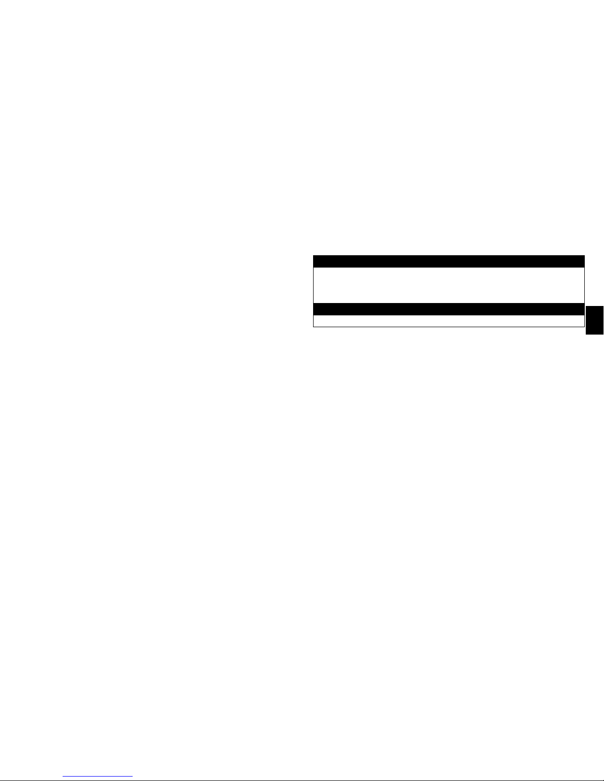
25
DEUTSCH
ANMERKUNG: Wird postoperativ kein Blutuss mit dem Monitor erkannt, müssen Sie gemäß den
klinischen Indikationen für den Patientenstatus vorgehen.
ANMERKUNG: Das Dopplersignal kann während des Überwachungszeitraums schwanken.
10. Zum Entfernen des Messfühlers zuerst Nahthülse und Draht von der Haut lösen (Naht, Klebeband
bzw. Klammer entfernen). Den Messfühler durch vorsichtiges Ziehen am Draht entfernen. Dabei
gleichzeitig an der Inzisionsstelle Gegendruck ausüben. Messfühler vollständig herausziehen.
Untersuchen, um sicherzustellen, dass die Messfühlerspitze vollständig intakt ist. Wenn der
Messfühler nicht mit herausgezogen wurde, muss er chirurgisch entfernt werden.
Geräte: Anastomoseinstrument, Messinstrument für Gefäße, COUPLER-Zangen und
Sterilisationsbehälter.
SPEZIELLE ANWEISUNGEN
WARNHINWEISE
• Anastomoseinstrument, Messinstrument für Blutgefäße, COUPLER-Zangen und Sterilisationsbehälter
werden unsteril geliefert und müssen vor der Verwendung sterilisiert werden.
• Das Anastomoseinstrument, das Messinstrument für Blutgefäße, die COUPLER-Zangen und der
Sterilisationsbehälter müssen vor der Verwendung gründlich kontrolliert werden. Beschädigte und/oder
reparaturbedürftige Instrumente dürfen nicht verwendet werden.
EINSCHRÄNKUNGEN FÜR DIE WIEDERAUFBEREITUNG
Keine speziellen Einschränkungen
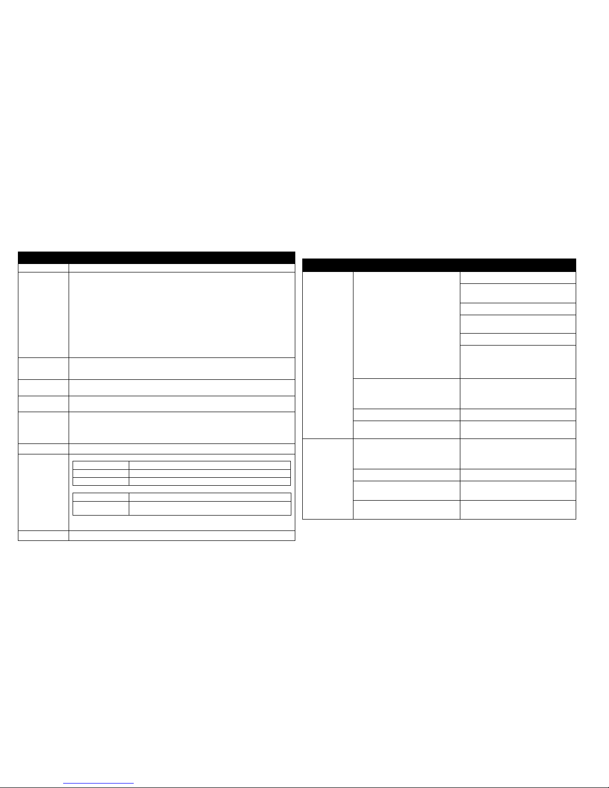
26
ANWEISUNGEN
Verwendungsort: Alle Instrumente nach Gebrauch mit Wasser abspülen.
Vorbereitung für
die Reinigung:
Reinigung:
Automatisch
1.
Jedes Instrument nach jeder Verwendung mit einem neutralen (pH 7–10) Reinigungsmittel
von Blut und Geweberesten reinigen. Jedes Instrument mit einer weichen Bürste reinigen.
Besonders auf Bereiche achten, in denen sich Gewebereste ansammeln können.
SICHERHEITSHINWEIS: Bei Verwendung eines Reinigungsmittels mit einem
pH-Wert von mehr als 10 wird die Eloxidschicht des Anastomoseinstruments und des
Sterilisationsbehälters zerstört.
2. Keine Materialien verwenden, die die Oberäche der Instrumente beschädigen oder
zerkratzen können.
3. Die Instrumente gründlich unter laufendem Wasser abspülen. Einen feinen Strahl durch
das Loch im Griffende des Anastomoseinstruments einbringen und während des Spülens
den Freigabeschalter drücken, um die Reinigung aller Oberächen des Instruments zu
gewährleisten.
Mindestens 10 Minuten lang in einer automatischen Spülmaschine bei einer Temperatur von
45–55 ºC mit einer neutralen (pH 7–10) Reinigungslösung reinigen.
Reinigung:
Manuell
Die Instrumente in einem Ultraschallbad mit einer neutralen (pH 7–10) Reinigungslösung
15 Minuten lang reinigen. Das Anastomoseinstrument erneut gründlich abspülen und einen
feinen Wasserstrahl durch das Loch im Griffende des Anastomoseinstruments einbringen.
Desinfektion: (Optional) Instrument mithilfe einer automatischen Spülmaschine bei einer Temperatur von 90
bis 95 °C mindestens 5 Minuten lang thermisch desinzieren.
Trocknen: Nach der Reinigung durch manuelle oder automatische Reinigungsmethoden sicherstellen, dass
die Instrumente vollständig trocken sind. Nicht 100 °C für 30 Minuten überschreiten.
Wartung,
Inspektion
und Tests:
• Zur Sicherung der fortgesetzten Qualität der Instrumente sicherstellen, dass jegliche sichtbare
Verschmutzung entfernt wurde.
• Das gereinigte Anastomoseinstrument (unter Einschluss des Griffs) vor der Sterilisation
mit einem wasserlöslichen Schmiermittel anfeuchten. Ein Unterlassen der Reinigung und
Anfeuchtung des Anastomoseinstruments kann zur Fehlfunktion des Instruments führen.
Verpackung: Verpacken Sie die Geräte mit der für den ausgewählten Sterilisationszyklus geeigneten Methode.
Sterilisation: SCHWERKRAFT-AUTOKLAVEN
Temperatur Empfohlene Einwirkungszeit (nicht Gesamtdauer des Zyklus)
250 °F (121 °C) 15 Minuten (mit oder ohne Einwickeln)
270 °F (132 °C) 3 Minuten(ohne Einwickeln)/10 Minuten (mit Einwickeln)
AUTOKLAVEN MIT VORVAKUUM
Temperatur Empfohlene Einwirkungszeit (nicht Gesamtdauer des Zyklus)
270 °F–273 °F
(132 °C–134 °C)
3–5 Minuten (ohne Einwickeln)
4–5 Minuten (mit Einwickeln)
ANMERKUNG: Es wird empfohlen, dass jede Einrichtung die Efzienz des verwendeten
Sterilisationsvorgangs etabliert.
Lagerung Empfohlene Lagerung bei kontrollierter Raumtemperatur von 20–25 °C (68–77 °F)
ANLEITUNG ZUR FEHLERBEHEBUNG FÜR DEN MESSFÜHLER
SYMPTOME MÖGLICHES PROBLEM LÖSUNG
Keine akustische
Ausgabe während
der Operation
Kein Feuchtigkeitskontakt Irrigation des Bereichs
Sicherstellen, dass keine Gefäßstriktur
vorliegt
Blutuss (Vene und Arterie) überprüfen
Blutgefäß massieren, um Blutdruck zu
erhöhen
Warten, bis Blutuss sicht- und hörbar ist
Ischämie bzw. Reperfusionsrate kann das
anfängliche Doppler-Signal verzögern
oder beeinträchtigen. Mit handgeführtem
Messfühler überprüfen.
Keine Stromversorgung Alle Verbindungen überprüfen:
• Messfühleranschluss an externes
Kabel
• Externes Kabel zum Monitor
Externes Kabel funktioniert nicht Externes Kabel austauschen
Messfühler funktioniert nicht Klinische Indikationen für den
Patientenstatus beachten.
Keine akustische
Ausgabe nach
der Operation
Keine Stromversorgung Alle Verbindungen überprüfen:
• Messfühleranschluss an externes
Kabel
• Externes Kabel zum Monitor
Externes Kabel funktioniert nicht Externes Kabel austauschen
Messfühler hat möglicherweise den
Kontakt mit dem Blutgefäß verloren.
Klinische Indikationen für den
Patientenstatus beachten.
Messfühler funktioniert nicht Klinische Indikationen für den
Patientenstatus beachten.

27
DEUTSCH
ANLEITUNG ZUR FEHLERBEHEBUNG FÜR DEN MONITOR
SYMPTOME MÖGLICHES PROBLEM LÖSUNG
Keine akustische
Ausgabe
Keine Stromversorgung Überprüfen, ob Monitor eingeschaltet ist
Keine Stromversorgung Alle Verbindungen überprüfen:
• Messfühleranschluss an externes Kabel
• Externes Kabel zum Monitor
• Monitor zum Netzteil
• Netzteil zum Netzkabel
• Netzkabel zur Steckdose
Lautstärke ist zu gering Lautstärke mit Lautstärke-erhöhen-Schalter
einstellen
Falscher Kanal wird verwendet Überprüfen, ob der richtige Kanal leuchtet
Batterien sind leer Batterien ersetzen oder Netzteil verwenden
Monitor funktioniert nicht Einen anderen Monitor anschließen
Monitor funktioniert nicht Synovis Micro Companies Alliance
kontaktieren
Schwache
akustische Ausgabe
Schwache Batterien
(Batterie-schwach-Anzeige leuchtet)
Batterien ersetzen oder Netzteil verwenden
Lautstärke ist zu gering Lautstärke mit Lautstärke-erhöhen-Schalter
einstellen
Monitor funktioniert nicht Einen anderen Monitor anschließen
Monitor funktioniert nicht Synovis Micro Companies Alliance
kontaktieren
KUNDENDIENST:
Für Kundendienst oder technische Hilfe setzen Sie sich in Verbindung mit:
Telefon: + 205 941 0111 oder 1 800 510 3318
Fax: + 205 941 1522
Website: synovismicro.com
GEWÄHRLEISTUNGSAUSSCHLUSS:
Synovis Micro Companies Alliance, Inc., (SMCA), eine Tochtergesellschaft von Synovis Life
Technologies, Inc., garantiert angemessene Sorgfalt bei der Herstellung dieses Geräts. Diese
Gewährleistung gilt ausschließlich und tritt an die Stelle aller sonstigen Gewährleistungen, seien sie
in ausdrücklicher, impliziter oder mündlicher Form gegeben, einschließlich unter anderem eventueller
impliziter Gewährleistungen für Marktgängigkeit oder Eignung. Aufgrund dieser Tatsache und
weil SMCA keine Kontrolle über die Bedingungen, unter denen das Gerät eingesetzt wird, über
die Diagnose der Patienten und über die Handhabung und Bedienung hat, nachdem das Gerät nicht
mehr in seinem Besitz ist, übernimmt SMCA weder die Garantie für eine gute Wirkung noch die
Haftung im Falle negativer Auswirkungen nach seiner Anwendung. Der Hersteller übernimmt keine
Verantwortung für direkte, indirekte, zufällige, nachfolgende oder andere Schäden oder Kosten, die
direkt oder indirekt aus der Verwendung des Geräts resultieren. SMCA leistet Ersatz für alle Geräte,
die sich als zum Zeitpunkt des Versands fehlerhaft erweisen. Kein Vertreter von SMCA ist berechtigt,
von vorgenannten Bestimmungen abzuweichen oder zusätzliche Haftung oder Verantwortung in
Verbindung mit diesem Gerät zu übernehmen.
LITERATUR:
1. DeLacure M and Wang H: Magnetic Resonance Imaging Assessment of a Microvascular
Anastomotic Device for Ferromagnetism. Journal of Reconstructive Microsurgery 13:8, 1997.
2. Caution needed when performing MRI scans on patients with aneurysm clips. FDA Medical
Bulletin Volume 23, Number 2, June 1993.
28
DEFINIZIONI DEI SIMBOLI:
I seguenti simboli e le denizioni riguardano unicamente il dispositivo GEM FlowCOUPLER:
Dimensioni del dispositivo GEM FlowCOUPLER
(diametro interno degli anelli del FlowCOUPLER)
Fare riferimento al paragrafo Istruzioni per l’uso
Non riutilizzare
Utilizzo entro
Sterilizzato con ossido di etilene
Non usare se la barriera di sterilizzazione del prodotto o la sua confezione sono
state compromesse.
I seguenti simboli e le denizioni riguardano il dispositivo e il sistema GEM FlowCOUPLER:
Attenzione, consultare i documenti forniti insieme allo strumento.
Il prodotto e la confezione non sono realizzati con lattice di gomma naturale.
Prodotto negli Stati Uniti
Contenuto
ATTENZIONE: la legge federale degli Stati Uniti limita la vendita ai soli
medici o su prescrizione medica.
Parte applicata di tipo CF
Trasmettitore RF
Corrente continua
Numero di catalogo
Numero di lotto
Numero articolo
Numero di tracciabilità
Produttore
Rappresentante autorizzato nella Comunità Europea
Consultare l’opuscolo delle istruzioni (simbolo bianco su fondo blu)
DESCRIZIONE:
Il dispositivo e il sistema Synovis MCA GEMTM FlowCOUPLER® sono stati specicamente
progettati per essere utilizzati nell'ambito dell'anastomosi termino-terminale dei vasi sanguigni e
della rilevazione del usso sanguigno presso il sito anastomotico. In base alle esigenze, il usso
sanguigno può essere rilevato no a un massimo di 7 giorni.
Il sistema FlowCOUPLER comprende un dispositivo e un monitor FlowCOUPLER. Il dispositivo
FlowCOUPLER comprende un trasduttore Doppler a ultrasuoni a 20 MHz (sonda) collegato a
uno degli anelli FlowCOUPLER e un elettrocatetere esterno. Gli anelli FlowCOUPLER sono in
polietilene ad alta densità e includono perni in acciaio inossidabile per uso chirurgico. Una copertura
di protezione e un gruppo ganasce proteggono gli anelli e la sonda che consentono di caricare
facilmente il dispositivo sullo strumento anastomotico. Sia la copertura di protezione sia il gruppo
ganasce sono monouso.
Gli accessori del sistema FlowCOUPLER comprendono uno strumento anastomotico riutilizzabile
(titanio e acciaio inossidabile per uso chirurgico), un calibro riutilizzabile per la misurazione dei
vasi (acciaio inossidabile per uso chirurgico), una pinza COUPLER (acciaio inossidabile per uso
chirurgico) e un vassoio per sterilizzazione (alluminio anodizzato).
INDICAZIONI PER L’USO:
Il FlowCOUPLER è un dispositivo impiantabile monouso progettato per essere utilizzato nell'ambito
dell'anastomosi termino-terminale di vene e arterie individuate normalmente durante le procedure
microchirurgiche e di ricostruzione vascolare. Il dispositivo FlowCOUPLER comprende una coppia
di anelli impiantati in modo permanente che ssano l'anastomosi e una sonda Doppler rimovibile che
viene accoppiata a pressione su uno degli anelli. Quando il dispositivo FlowCOUPLER è utilizzato
insieme al monitor FlowCOUPLER, lo scopo del sistema FlowCOUPLER è rilevare il usso
del sangue e confermare la pervietà dei vasi durante e dopo l'intervento chirurgico presso il sito
anastomotico. A livello post-operatorio, il usso sanguigno può essere rilevato in base alle esigenze
no a 7 giorni. La sonda Doppler del FlowCOUPLER non è progettata per essere un impianto
permanente e va rimossa da 3 a 14 giorni dopo l'intervento chirurgico.
CONTROINDICAZIONI:
Il FlowCOUPLER non è indicato per essere usato nell'ambito dell'anastomosi termino-laterale o in
pazienti che presentano condizioni tali da precludere, di norma, la riparazione microvascolare con la
tecnica di sutura. Esempi di tali condizioni includono, tra l'altro:
• patologia vascolare periferica preesistente o sospetta
• irraggiamento in corso dell'area di ricostruzione
• infezione clinica dell'area di ricostruzione
• infezione prevista dovuta a una signicativa contaminazione dell'area di ricostruzione
• friabilità del tessuto vascolare dovuta a condizioni sclerotiche
• diabete mellito concomitante
EO

29
ITALIANO
• terapia corticosteroidea concomitante
L’uso del dispositivo e del sistema FlowCOUPLER è controindicato nel sistema circolatorio
centrale.
AVVERTENZE:
• Il mancato utilizzo del calibro per la misurazione dei vasi per calcolare approssimativamente
le dimensioni del vaso potrebbe dar luogo all'utilizzo di un dispositivo FlowCOUPLER di
misura inadeguata. L'utilizzo di un anello troppo grande per il vaso potrebbe dar luogo a una
sollecitazione o una lacerazione della parete del vaso e alla compromissione dell'anastomosi.
L’utilizzo di un anello troppo piccolo per il vaso potrebbe costringere eccessivamente il vaso e
provocare trombosi o separazione dell’anello.
• La mancata compressione delle ganasce del FlowCOUPLER con un emostato o con uno strumento
analogo prima dell'espulsione degli anelli uniti potrebbe dar luogo a un inadeguato incastro ad
attrito e alla possibile separazione dell'anello. Ispezionare il sito anastomotico per assicurarsi che
l'anastomosi sia stata completata in modo soddisfacente.
• Il FlowCOUPLER viene fornito sterile ed è esclusivamente monouso. Non risterilizzare né
riutilizzare il FlowCOUPLER.
- La risterilizzazione può compromettere l’integrità strutturale del prodotto, con conseguente
anastomosi incompleta.
- Il dispositivo non può essere riutilizzato a causa di possibili danni strutturali subiti nel corso del
primo impiego, i quali possono determinare un’anastomosi incompleta.
• Non utilizzare il dispositivo COUPLER se la confezione è aperta o sembra danneggiata o rovinata,
poiché la sterilità potrebbe essere stata compromessa. La mancata ottemperanza di tale avvertenza
potrebbe causare un'infezione chirurgica.
• L'uso sicuro del dispositivo FlowCOUPLER per l'anastomosi di strutture tubolari diverse dalle
vene e dalle arterie non è stato valutato.
• L'uso sicuro del dispositivo FlowCOUPLER per l'anastomosi di vasi in fase di crescita nei
bambini o negli adolescenti non è stato valutato. Non destinato all’uso su un feto.
• L'uso sicuro della parte della sonda del FlowCOUPLER durante le procedure di IRM non è stato
valutato. Di conseguenza, la sonda va rimossa prima di una procedura di IRM.
• La sicurezza di un'anastomosi con FlowCOUPLER che siano stati avvicinati, riaperti e quindi
riavvicinati non è stata dimostrata. Quando si desidera riavvicinare l'anastomosi, è necessario
rimuovere il vaso da ciascun anello e utilizzare un nuovo dispositivo FlowCOUPLER.
• Assicurarsi che connettori e manicotto di sutura non siano impiantati.
• Lo strumento anastomotico, il calibro per la misurazione dei vasi, la pinza COUPLER e il vassoio
di sterilizzazione devono essere sterilizzati prima dell'uso.
• Lo strumento anastomotico, il calibro per la misurazione dei vasi, la pinza COUPLER e il vassoio
di sterilizzazione devono essere controllati attentamente prima dell'uso. Non utilizzare strumenti
danneggiati e/o che debbano essere riparati.
NORME PRECAUZIONALI:
• L'uso del dispositivo FlowCOUPLER comporta i potenziali rischi normalmente associati a un
dispositivo impiantato, ad es. infezione, perforazione o lacerazione di vasi, erosione, rigetto
dell'impianto o spostamento/migrazione del dispositivo.
• L'angolo del lo della sonda relativamente al lembo dipenderà dall'orientamento dello strumento
anastomotico durante la formazione dell'anastomosi. Per evitare che il vaso si pieghi o si attorcigli
inavvertitamente durante il posizionamento del lembo, evento che potrebbe portare a una scarsa
perfusione del lembo, è necessario fare attenzione nello stabilire l'angolo desiderato del lo della
sonda relativamente al lembo e regolare lo strumento anastomotico di conseguenza prima di
iniziare l'anastomosi.
• Nel caso in cui una sonda venga rimossa prematuramente dal relativo supporto, non tentare di
reinserirla. Rimuovere invece gli anelli e impiantare un nuovo dispositivo FlowCOUPLER.
• Il lo della sonda è delicato. L'uso di pinze che provocano schiacciamento potrebbe
danneggiare il lo della sonda.
• Prestare attenzione durante la manipolazione del lo della sonda. Le piegature marcate
possono provocare danni al lo della sonda.
• L'uso di morsetti sul lo dell'elettrocatetere esterno potrebbe danneggiare quest’ultimo.
• La sonda non è progettata per essere un impianto permanente e va rimossa da 3 a 14 giorni dopo
l'intervento chirurgico.
• Evitare di applicare una forza eccessiva per rimuovere la sonda dal paziente: ciò potrebbe causare
lesioni al vaso sanguigno. Se non è possibile rimuovere la sonda con una trazione delicata,
rimuoverla chirurgicamente. Non tagliare il lo della sonda.
• Durante la sua rimozione, assicurarsi che la sonda sia collegata al relativo lo. In caso contrario,
sarà necessario rimuovere la sonda chirurgicamente.
• Il FlowCOUPLER va utilizzato esclusivamente con il monitor GEM FlowCOUPLER.
• Durante l'impiego dei dispositivi ad ultrasuoni, l'operatore dovrebbe minimizzare l'esposizione
del paziente all'energia ultrasonica, in base al principio dell'ALARA (As Low As Reasonably
Achievable - tanto basso quanto ragionevolmente ottenibile).
ISTRUZIONI PER L'USO:
Queste Istruzioni per l'uso sono state progettate per l'uso adeguato di questo dispositivo. Non sono
destinate a servire come riferimento per la tecnica chirurgica, né a sostituire protocolli istituzionali o
giudizi clinici professionali riguardanti la cura del paziente.
È responsabilità del medico informare il paziente che è destinatario di impianti permanenti
contenenti componenti metallici (perni in acciaio inossidabile per uso chirurgico). I FlowCOUPLER

30
sono stati valutati con un campo magnetico da 1,5 Tesla e non è stato osservato alcun cambiamento
nello spostamento in ciascuno dei tre piani ortogonali.¹ I perni in acciaio inox dei FlowCOUPLER
sono nominalmente non ferromagnetici. Tuttavia, la Food and Drug Administration (FDA) degli
Stati Uniti ha emesso raccomandazioni in merito a tutti i dispositivi medici impiantati contenenti
componenti metallici, quali:
• documentazione dell'identità dell'impianto nella cartella clinica ufciale (produttore, numero di
modello, numeri di lotto e di serie e segni di identicazione, se presenti);
• documentazione della tecnica e dei risultati di qualsiasi test magnetico realizzato sull'impianto o
del fatto che non sia stato eseguito alcun test di tale natura;
• istruzioni ai pazienti riguardo al particolare impianto e la raccomandazione di identicare la
scheda di allerta medica, il braccialetto o la collana che caratterizza il dispositivo impiantato.²
COUPLER DA 3,0 MM O INFERIORE:
ANASTOMOSI TERMINO-TERMINALE:
Utilizzando la tecnica microchirurgica convenzionale, mobilizzare almeno 1 cm di ogni estremità
del vaso. Usando morsetti vascolari, tenere fermi i vasi e irrigarne le aperture. Il FlowCOUPLER
ha bisogno di una quantità maggiore di vaso libero nei morsetti rispetto alla riparazione con sutura
convenzionale.
1. Dopo una leggera dilatazione, misurare il diametro esterno di ogni vaso usando il calibro per
la misurazione dei vasi. Le guide circolari sul calibro non devono essere collocate all'interno
del lume del vaso (vedere Figura 1). Se vi è una discrepanza tra le dimensioni dei due vasi,
usare la misura del vaso più piccolo per scegliere il dispositivo FlowCOUPLER appropriato. Il
grado di spasmo e l'elasticità del vaso devono essere considerati quando si sceglie la misura del
dispositivo FlowCOUPLER da utilizzare.
2. Selezionare la misura appropriata del FlowCOUPLER. Entrambe le estremità dei vasi
devono essere approssimativamente della stessa misura del diametro interno del dispositivo
FlowCOUPLER selezionato.
3. Rimuovere il coperchio dal vassoio esterno e rimuovere asetticamente il vassoio interno; il
vassoio interno può essere collocato nel campo sterile. Ispezionare il vassoio interno. Non usarlo
se il vassoio interno è danneggiato o se le chiusure ermetiche non sono intatte. Rimuovere il
coperchio dal vassoio interno.
4. Ruotare la manopola dello strumento anastomotico completamente in senso antiorario e inserire
il FlowCOUPLER sullo strumento anastomotico quando il FlowCOUPLER è ancora sul vassoio.
Le frecce coincidenti dell'indicatore sul FlowCOUPLER e lo strumento anastomotico
devono essere rivolte l'una verso l'altra durante il caricamento (vedere Figure 2 e 3).
Assicurarsi di aver udito un clic che confermi il corretto caricamento.
5. Rimuovere il FlowCOUPLER dal vassoio e dalla copertura di protezione facendo attenzione a
non tirare il lo (vedere Figura 4).
6. Vericare il funzionamento della sonda collegandola al monitor e irrigando la punta della sonda
collegata con soluzione salina sterile (fare riferimento alla sezione Rilevamento del usso di
queste Istruzioni per l'uso per istruzioni sul corretto collegamento). Un segnale acustico del
monitor conferma il funzionamento adeguato del dispositivo. Se non si rileva alcun segnale, fare
riferimento alla sezione Risoluzione dei problemi di queste Istruzioni per l'uso.
7. Ispezionare visivamente per vericare che entrambi gli anelli si trovino sul fondo della porzione
a U della ganascia e che i perni non siano piegati (vedere Figure 5a e 5b). Se i perni sono
piegati, non tentare di raddrizzarli. Utilizzare invece un dispositivo FlowCOUPLER nuovo.
NOTA: per evitare che il vaso si pieghi o si attorcigli inavvertitamente durante il posizionamento
del lembo, è necessario prestare attenzione nello stabilire l'angolo desiderato del lo della sonda
relativamente al lembo e regolare lo strumento anastomotico di conseguenza prima di iniziare
l'anastomosi.
8. Collocare lo strumento anastomotico perpendicolarmente ai vasi, con il gruppo ganasce del
FlowCOUPLER vicino alle due estremità del vaso. Tirare l'estremità di un vaso attraverso uno
degli anelli del FlowCOUPLER usando una pinza microchirurgica (vedere Figura 6). Prestare
attenzione per evitare di attorcigliare il vaso.
9. Prendere la misura approssimativa dei diametri della parete del vaso e del rivestimento interno
tra due perni, rovesciare di 90 gradi e inlzare su un perno. Procedere in modo triangolare,
inlzare fermamente il vaso su tutti gli altri perni, completando tre perni (vedere Figura
7). Completare la collocazione del vaso sull'anello inlzando il vaso sui rimanenti tre perni
intermedi (vedere Figura 8). Assicurarsi che sia la parete del vaso sia lo strato interno siano
perfettamente inlzati su ogni perno per ridurre il rischio di trombosi. Nell'eventualità in cui la
parete del vaso si rompa durante l’inlzamento, rimuovere il vaso, rinire l’estremità e ripetere
la procedura. Per esempi di inlzamento inappropriato del vaso, fare riferimento alla Figura
9.
10. Ripetere le Fasi 8 e 9 per inlzare l'altra estremità del vaso sul secondo anello del
FlowCOUPLER.
11. Quando entrambe le estremità dei vasi sono state adeguatamente inlzate, controllare
visivamente per essere certi che entrambi gli anelli si trovino sul fondo della porzione a U della
ganascia e che i perni non siano piegati (vedere Figure 5a e 5b). Unire gli anelli (vedere Figure
10 e 11) ruotando in senso orario la manopola dello strumento anastomotico.
12. Prima di espellere gli anelli uniti, schiacciare delicatamente l'estremità delle ganasce
apposte con un piccolo emostato (vedere Figura 12) per assicurare l'avvicinamento
dell'anello e un incastro ad attrito stretto. Ruotare ulteriormente la manopola dello strumento
anastomotico in senso orario per espellere gli anelli uniti.
13. Vericare l'anastomosi al microscopio della sala operatoria prima di aprire i morsetti vascolari.
Rimuovere i morsetti e ispezionare il sito anastomotico per assicurarsi che l'anastomosi sia
stata completata in modo soddisfacente (vaso pervio senza perdita).
 Loading...