

Page 1

Using the Model 281xSA
Ethernet Hub
SynOptics Communications, Inc.
4401 Great America Parkway
Santa Clara, CA 95054
408-988-2400
May 1994
Page 2

© 1994 by SynOptics Communications, Inc. All rights reserved.
Trademarks
SynOptics and SynOptics Communications are registered trademarks of SynOptics
Communications, Inc. Model 281xSA Ethernet Hub, Expanded View, and Autotopology are
trademarks of SynOptics Communications, Inc.
Other brand and product names are registered trademarks or trademarks of their respective
holders.
Statement of Conditions
In the interest of improving internal design, operational function, and/or reliability, SynOptics
Communications, Inc. reserves the right to make changes to the products described in this
document without notice.
SynOptics Communications, Inc. does not assume any liability that may occur due to the use or
application of the product(s) or circuit layout(s) described herein.
One program, the Compression/Decompression Library, in this product contains free software;
you can distribute the Compression/Decompression Library and/or modify it under the terms of
the GNU General Public License as published by the Free Software Foundation; either version 2
or (at your option) any later version.
The Compression/Decompression Library is distributed in the hope that it will be useful, but
WITHOUT ANY WARRANTY; without even the implied warranty of MERCHANTABILITY
OR FITNESS FOR A PARTICULAR PURPOSE. See the GNU General Public License for more
details.
T o recei ve a copy of the source code for the Compression/Decompression Library, and associated
make files, free of charge, contact SynOptics Communications, Inc., attention Corporate
Secretary.
Federal Communications Commission (FCC) Statement
Note: This equipment has been tested and found to comply with the limits for a Class A digital
device, pursuant to Part 15 of the FCC rules. These limits are designed to provide reasonable
protection against harmful interference when the equipment is operated in a commercial
environment. This equipment generates, uses, and can radiate radio frequency energy. If it is not
installed and used in accordance with the instruction manual, it may cause harmful interference
to radio communications. Operation of this equipment in a residential area is likely to cause
harmful interference, in which case users will be required to take whatever measures may be
necessary to correct the interference at their own expense.
EN 55 022 Declaration of Conformance
This is to certify that the SynOptics Communications Model 281xSA Ethernet Hub is shielded
against the generation of radio interference in accordance with the application of Council
Directive 89/336/EEC, Article 4a. Conformity is declared by the application of EN 55 022:1987
Class B (CISPR 22:1985/BS 6527:1988).
Compliance with the applicable regulations is dependent upon the use of shielded cables.
ii 893-743-A
Page 3

Bestätigung des Herstellers/Importeurs
Es wird hiermit bestätigt, daß das Model 281xSA Ethernet Hub gemäß der im BMPT -AmtsblVfg
243/1991 und Vfg 46/1992 aufgeführten Bestimmungen entstört ist. Das vorschriftsmäßige
Betreiben einiger Geräte (z.B. Testsender) kann jedoch gewissen Beschränkungen unterliegen.
Lesen Sie dazu bitte die Anmerkungen in der Betriebsanleitung.
Das Bundesamt für Zulassungen in der T elek ommunikation wurde dav on unterrichtet, daß dieses
Gerät auf den Markt gebracht wurde und es ist berechtigt, die Serie auf die Erfüllung der
Vorschriften hin zu überprüfen.
Die Erfüllung der zutreffenden Vorschriften hängt von der Benutzung geschirmter Kabel ab. Der
Benutzer ist für den Erwerb der entsprechenden Kabel verantwortlich.
Certificate of the Manufacturer/Importer
It is hereby certified that the Model 281xSA Ethernet Hub has been suppressed in accordance
with the conditions set out in the BMPT -AmtsblVfg 243/1991 and Vfg 46/1992. The operation of
some equipment (for example, test transmitters) in accordance with the regulations may,
however, be subject to certain restrictions. Please refer to the notes in the operating instructions.
Federal Office for Telecommunications Approvals has been notified of the placing of this
equipment on the market and has been granted the right to test the series for compliance with the
regulations.
Compliance with the applicable regulations is dependent upon the use of shielded cables. It is the
responsibility of the user to procure the appropriate cables.
Voluntary Control Council for Interference (VCCI) Statement
Voluntary Control Council for Interference (VCCI) Statement
This equipment is in the 1st category (information equipment to be used in commercial and/or
industrial areas) and conforms to the standards set by the Voluntary Control Council for
Interference by Data Processing Equipment and Electronic Office Machines that are aimed at
preventing radio interference in commercial and/or industrial areas.
Consequently, when this equipment is used in a residential area or in an adjacent area thereto,
radio interference may be caused to equipment such as radios and TV receivers.
Compliance with the applicable regulations is dependent upon the use of shielded cables. The
user is responsible for procuring the appropriate cables. Read instructions for correct handling.
893-743-A iii
Page 4

iv 893-743-A
Page 5

Contents
Preface
Purpose xv
Audience xv
Conventions xvi
Special Message Formats xvi
Two-tiered Procedure Format xvi
Use of Enter, Type, and Press xvi
Other Conventions xvii
Related Publications xvii
SynOptics Customer Support xviii
Chapter 1 Overview of the Model 281xSA Hub
Features 1-2
Functional Description 1-3
Management Functions in the Model 281xSA Hubs 1-4
Dedicated Data Collection 1-4
SNMP-based Management 1-4
Agent Software 1-5
MIB-II 1-5
Support for SynOptics Optivity Features 1-6
Expanded View 1-6
Autotopology 1-6
Show Nodes/Find Nodes 1-6
Allowed Nodes Security 1-6
Thresholds 1-7
Service Port Management 1-7
Chapter 2 Installing the Model 281xSA Hub
Site Preparation 2-1
Operating Environment Requirements 2-2
Physical Location Requirements 2-2
Package Contents 2-3
Required Tools and Materials 2-4
Table or Shelf Installation 2-5
Rack Installation 2-7
Wall Installation 2-10
893-743-A v
Page 6

Chapter 3 Network Configurations and Cable Connections
Building Network Configurations 3-2
Single-hub Network 3-3
Ethernet Station Connections 3-3
Cable Connections in the Work Area 3-4
Using an AUI Network Interface Card 3-4
Using a 10BASE-T Interface Card 3-6
Cable Connections in the Wiring Closet 3-7
Cluster Configurations 3-11
Cluster Operation 3-12
Connecting a Cluster Configuration 3-12
Multiple-hub Networks—System 2000 Only 3-14
Configuration Rules 3-14
Interconnecting Model 2813SA Hubs Using the AUI Port 3-14
Connecting the AUI Port to a Fiber Backbone 3-15
Connecting the AUI Port to Coaxial Backbone 3-16
Interconnecting Model 2814SA Hubs Using the 10BASE-FL Port 3-18
Interconnecting Hubs Using the MDI Port 1 3-19
Multiple-hub Networks—Including System 3000 Products 3-20
Chapter 4 Configuring the Model 281xSA Hub for IP/IPX Networks
Required Network Information and Configuration Actions 4-1
IP/IPX and BootP Network Configuration Options 4-2
Using the Service Port 4-3
Terminal Connection Requirements 4-3
Connecting to the Model 281xSA Service Port 4-3
Power-on Self-test Diagnostic Messages Display 4-5
Summary of the Boot Sequence with a BootP Server 4-7
Setting the Boot Configuration without a BootP Server 4-8
Using Configuration Menus 4-12
Commands 4-14
Boot Configuration Menus 4-15
Boot Configuration Commands 4-16
System Configuration Menu 4-21
Boot File Configuration Menu 4-22
IP Configuration Menu 4-24
IPX Configuration Menu 4-25
vi 893-743-A
Page 7

Setting Run-time Parameters 4-27
Protocol Parameters Menu 4-29
IP Parameters Menu 4-31
IPX Parameters Menu 4-33
SNMP Parameters Menu 4-34
SNMP Trap Receivers for IP 4-36
SNMP Trap Receivers for IPX 4-37
Out-of-Band Parameters Menu 4-40
Setting Security Parameters 4-41
Profile Parameters Menu 4-43
Boot Parameters Menu 4-44
Appendix A Technical Specifications
Appendix B LEDs and Switches
Reset Button B-4
MDI-X/MDI Switch B-4
Appendix C Pin Assignments
AUI Port C-1
10BASE-T Ports C-1
RS-232 Port C-2
Using the RS-232 Serial Port for an Out-of-band Connection C-3
Service Port C-4
Appendix D Link Integrity Test Function
Appendix E Autopolarity Detection and Correction
Appendix F IP Addressing
Classes of Internet Addresses F-1
Internet Address Notation F-2
Allowable Internet Addresses F-3
Internet Address Conventions F-3
Addresses and Routing F-4
Subnetting F-4
Subnetting and Routing F-5
Subnet Masks F-5
893-743-A vii
Page 8

Appendix G Setting Up the Model 281xSA Hub Configuration File
Sample Configuration File G-1
Configuration Parameters G-9
Appendix H System Messages
System Operation Display Messages H-1
Service Port Boot Messages H-2
TFTP Error and Information Messages H-2
Memory Error Messages H-5
Reset Message H-5
Service Port Run-time Messages H-6
Configuration File Messages H-7
Appendix I Replacing SIMMs
Preparation I-2
Tools and Equipment I-2
Preparatory Steps I-2
Removing the Cover I-3
Replacing the SIMM I-5
Setting Jumpers I-10
Reinstalling the Cover I-11
Final Steps I-12
Index
viii 893-743-A
Page 9

Figures
Figure 1-1. Model 2813SA Ethernet Hub 1-1
Figure 1-2. Model 2814SA Ethernet Hub 1-1
Figure 2-1. Model 281xSA hub package contents 2-4
Figure 2-2. Attaching feet 2-5
Figure 2-3. Connecting the power cord 2-5
Figure 2-4. Power LED 2-6
Figure 2-5. Attaching brackets for rack installation 2-7
Figure 2-6. Installing the hub in an equipment rack 2-8
Figure 2-7. Connecting the power cord 2-9
Figure 2-8. Power LED 2-9
Figure 2-9. Attaching brackets for wall mounting 2-10
Figure 2-10. Template for wall mounting 2-11
Figure 2-11. Securing the Model 281xSA hub to the wall 2-12
Figure 2-12. Connecting the power cord 2-12
Figure 2-13. Power LED 2-13
Figure 3-1. Typical single-hub configuration 3-3
Figure 3-2. Connecting an AUI cable to a Model 508B 10BASE-T
Transceiver 3-4
Figure 3-3. Connecting a Model 928 transceiver to a network
station 3-5
Figure 3-4. Connecting UTP cable to a Model 508B transceiver 3-5
Figure 3-5. Connecting the Model 928 transceiver to the wall 3-6
Figure 3-6. Connecting a 10BASE-T interface card 3-7
Figure 3-7. MDI-X/MDI switch set to the MDI-X position 3-8
Figure 3-8. Connecting 25-pair UTP cable 3-9
Figure 3-9. Model 281xSA hub 10BASE-T port connection 3-10
Figure 3-10. Typical Model 2813/2803 cluster configuration 3-11
Figure 3-11. Connecting a cluster configuration 3-13
Figure 3-12. Interconnecting Model 2813SA hubs using an IEEE 802.3
10BASE-FL transceiver 3-15
Figure 3-13. Interconnecting Model 281xSA hubs using coaxial
backbone 3-17
Figure 3-14. Connecting Model 2814SA hubs using the 10BASE-FL
port 3-18
Figure 3-15. Interconnecting hubs via the MDI port 3-19
Figure 3-16. MDI-X/MDI switch set to MDI 3-20
893-743-A ix
Page 10

Figure 3-17. Network including a Model 3000 concentrator 3-21
Figure 3-18. Fully manageable network composed entirely
of Model 281xSA clusters and single hubs 3-22
Figure 4-1. Hardware address label 4-1
Figure 4-2. Diagnostic messages for the Model 281xSA hub 4-5
Figure 4-3. BootP service port screen display 4-6
Figure 4-4. Boot main menu 4-9
Figure 4-5. Boot messages (remote image file load) 4-10
Figure 4-6. Boot messages (local image file load) 4-11
Figure 4-7. Primary boot configuration menus 4-12
Figure 4-8. Run-time parameters menus 4-13
Figure 4-9. Sample configuration menu 4-14
Figure 4-10. Boot main menu 4-15
Figure 4-11. System Configuration menu 4-21
Figure 4-12. Boot File Configuration menu 4-22
Figure 4-13. IP Configuration menu 4-24
Figure 4-14. IPX Configuration menu 4-26
Figure 4-15. Menu for changing run-time parameters 4-27
Figure 4-16. Protocol Parameters menu 4-29
Figure 4-17. IP Parameters menu 4-31
Figure 4-18. Changing the IP parameters 4-32
Figure 4-19. IPX Parameters menu 4-33
Figure 4-20. SNMP Parameters menu 4-34
Figure 4-21. SNMP IP Trap Receivers menu 4-36
Figure 4-22. SNMP IPX Trap Receivers menu 4-38
Figure 4-23. Out-of-Band Parameters menu 4-40
Figure 4-24. Set Security Parameters menu 4-42
Figure 4-25. Profile Parameters menu 4-43
Figure 4-26. Boot Parameters menu 4-44
Figure B-1. Model 2813SA Ethernet Hub front panel B-1
Figure B-2. Model 2814SA Ethernet Hub front panel B-1
Figure B-3. Reset button B-4
Figure B-4. Internal crossover function B-5
Figure B-5. External crossover function B-5
Figure B-6. MDI-X/MDI switch B-6
x 893-743-A
Page 11

Figure F-1. Class A Internet Address F-1
Figure F-2. Class B Internet Address F-1
Figure F-3. Class C Internet address F-2
Figure F-4. Subnet field in a Class B address F-4
Figure I-1. Cover retaining screws I-3
Figure I-2. Removing the hub cover I-4
Figure I-3. SIMM location I-6
Figure I-4. Removing a SIMM I-7
Figure I-5. Installing a SIMM I-8
Figure I-6. DRAM jumpers I-10
Figure I-7. Reinstalling the cover I-11
Figure I-8. Cover retaining screws I-12
893-743-A xi
Page 12

xii 893-743-A
Page 13

Tables
Table B-1. Model 281xSA hub LEDs B-2
Table B-2. Model 281xSA hub µP Fault and On Line LED
combinations B-3
Table C-1. AUI port pin assignments (DB-15 socket) C-1
Table C-2. 10BASE-T port pin assignments (RJ-45 jack) C-2
Table C-3. RS-232 interface port pin assignments (DB-25 plug) C-2
Table C-4. Service port pin assignments (DB-9 plug) C-4
Table F-1. Reserved and available Internet addresses F-3
Table F-2. Subnet masks F-5
Table H-1. System operation messages H-1
Table I-1. DRAM SIMM capacities and types I-5
Table I-2. Jumper settings for total memory I-10
893-743-A xiii
Page 14

xiv 893-743-A
Page 15

Preface
Purpose
Congratulations on your purchase of the SynOptics® Model 281xSA Ethernet
Hub. These standards-based 10B ASE-T hubs provide networking solutions for
low- and medium-density 10BASE-T networks that use Simple Network
Management Protocol (SNMP) network management.
This guide describes how to install and use the Model 281xSA Ethernet Hub,
including configuration rules for connecting Ethernet stations and making
network interconnections.
Configuration procedures for IP/IPX networks include instructions on how to
prepare the hub for configuration, an explanation of how to use configuration
menus, and descriptions of specific configuration menus and commands.
Audience
Before installing the Model 281xSA hub, read Chapter 3, “Network
Configurations and Cable Connections,” to plan the placement and connection
of hubs and Ethernet stations.
Throughout this guide,
System 2000
or
Model 28xx hub
is used to refer to the
Model 2803, 2804, 2813SA, or 2814SA hub, and Model 281xSA hub refers
to either the Model 2813SA or the Model 2814SA Ethernet Hub. Where a
reference is specific to one of the models, the specific model number is used.
This guide is intended for network installers or administrators who are
responsible for configuring, installing, or maintaining an Ethernet network with
Model 281xSA hubs. These individuals should have the following background
and experience:
Working knowledge of SNMP networking
■
Familiarity with setting up Ethernet, 10BASE-T, IP, and IPX networks
■
893-743-A xv
Page 16

Preface
Conventions
This section describes the conventions used in this guide.
Special Message Formats
This guide uses the following formats to highlight special messages:
NOTE:
This format is used to highlight information of importance or special
interest.
CAUTION:
prevent equipment failure or loss of data.
WARNING:
injury or equipment damage.
Two-tiered Procedure Format
The procedural steps in this guide are presented in a two-tiered format. The first
tier describes the step very briefly, but precisely. An experienced user may only
need to read the first tiers to complete the task. The second tier describes the
step in more detail and may include results of performing the step.
Use of Enter, Type, and Press
This guide uses enter, type, and press to describe the following actions:
■
When you read “enter,” type the text and press the Enter key.
This format is used to highlight information that will help you
This format is used to highlight material involving possibility of
When you read “type,” type the text, but do not press the Enter key.
■
■
When you read “press,” press only the alphanumeric or named key.
xvi 893-743-A
Page 17

Other Conventions
Related Publications
This guide uses the following typographical conventions:
italics
bold
Configuration file keywords.
courier font
Initial Caps Menu titles and window and button names.
[Enter] Named keys in text are shown enclosed in square
[Ctrl]+C Two or more keys that must be pressed simultaneously
ALL CAPS DOS file and directory names.
Related Publications
For more information about Ethernet networks, refer to the
3000 Ethernet Connectivity Guide
more information about network management, refer to the documentation that
was shipped with your SynOptics network management software.
Configuration file parameters; book titles; and UNIX
file, command, and directory names.
Screen text, user-typed command-line entries.
brackets. The notation [Enter] is used for the Enter key
and the Return key.
are shown in text linked with a plus (+) sign.
LattisNet System
(SynOptics part number 893-211-B). For
To purchase SynOptics product publications, order by part number from
SynOptics Press at the following numbers. You may also request a free catalog
of SynOptics Press product publications.
■
Phone: 1-800-845-9523
■
FAX: U.S/Canada: 1-800-582-8000, International: 1-916-939-1010
893-743-A xvii
Page 18

Preface
SynOptics Customer Support
For assistance with installing and configuring your SynOptics systems or
for post-installation questions or problems, contact your local reseller. If you
cannot contact your local reseller, call the SynOptics Technical Response
Center (TRC) Contract Hotline.
To contact the TRC Contract Hotline, call:
■
U.S. and Canada: 1-800-473-4911
Europe: 011-31-3480-31616
■
Rest of the world: 408-764-1000
■
Technical information is available from the SynOptics InfoFACTS fax-ondemand system by calling:
U.S. and Canada: 1-800-786-3228
■
■
International: 408-764-1002
You can also access technical information in the SynOptics forum on
CompuServe.
For information about our education services, contact the SynOptics Training
Coordinator at 1-800-473-4911 or 408-764-1018.
xviii 893-743-A
Page 19
Chapter 1 Overview of the Model 281xSA Hub
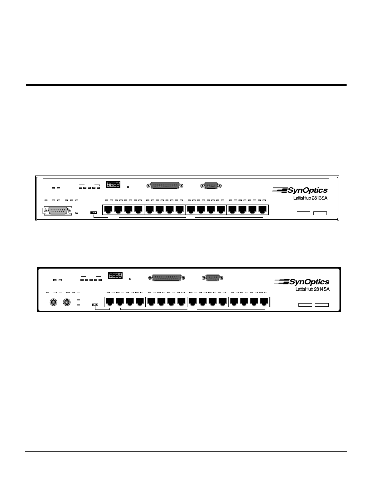
The Model 2813SA and 2814SA Ethernet Hubs (see Figure 1-1 and
Figure 1-2, respectively) are preconfigured for plug-and-play operation. These
workgroup hubs support 10BASE-T Ethernet in a manageable, physical star
configuration using a building’s existing premises wiring. Model 281xSA
Ethernet Hubs offer a cost-effective solution for high-power, low-density
10BASE-T departmental segments, as well as the flexibility and expandability
to support medium-density 10BASE-T workgroups operating within a large
enterprise network.
Expansion
2345
Partition
Int
AUI
System Operation
Link Part
MDI-X/MDI
Reset
123 4 567 8 910111213141516
RS-232 Service Port
MDI-X
Power
µP FaultOn Line
NM
Control
Isolate Data (Data) Col
AUI Port
4638
NM
Power
Control
TX RX
10BASE-FL Fiber Port
µP FaultOn Line
Isolate Data <Data> Col
Expansion
2345
Int
Partition
Link
Figure 1-1. Model 2813SA Ethernet Hub
System Operation
Link Part
MDI-X/MDI
Reset
123 4 567 8 910111213141516
RS-232 Service Port
MDI-X
Figure 1-2. Model 2814SA Ethernet Hub
The Model 281xSA Ethernet Hub includes fully integrated SNMP-based
Advanced Analyzer network management capabilities compatible with
SynOptics network management software or other SNMP-compatible network
management software.
This chapter includes the following topics:
A list of features of the Model 281xSA hub
■
4639
A summary of Model 281xSA hub functions
■
■
Descriptions of management options for the Model 281xSA hub
893-743-A 1-1
Page 20

Overview of the Model 281xSA Hub
Features
Each Model 281xSA Ethernet Hub has the following features:
Support for all RMON groups except packet capture and filter
■
■
Flash memory that allows local loading of image and configuration data
■
Sixteen IEEE 802.3i 10BASE-T ports:
– Shielded modular RJ-45 jacks for unshielded twisted pair (UTP) cable
– MDI/MDI-X configuration switch for port 1 to connect the Model
– MDI-X-only configuration for ports 2 through 16
or shielded twisted pair (STP) cable using a Model 822 10BASE-T-toType 1 Adapter
281xSA hub directly without using an external crossover cable or
adapter
– Per-port automatic link integrity test function
– Per-port automatic disconnection (autopartition) of a port for too many
consecutive collisions or a collision that is too long)
– Automatic +/– polarity detection and correction of the receive data
wire-pair for each port
One AUI port (on the Model 2813SA hub) for connecting an Ethernet
■
IEEE 802.3 transceiver—allowing connection to another network hub,
station, or segment using coaxial, fiber optic, or twisted pair cable
or
One optical port (on the Model 2814SA hub) for direct connection to fiber
■
optic cable
■
Front-panel LEDs displaying link and partition status of each port, power
status, data activity, collision, and AUI partition or fiber optic link status
Front panel system operation display showing network utilization
■
■
Front-accessible reset button
One service port, implemented on a DB-9 plug, for connection of a
■
terminal
1-2 893-743-A
Page 21

One standard RS-232 serial communications port, implemented on a
■
Functional Description
DB-25 plug, for out-of-band connection to the telephone voice network
through an external modem
■
Installation options on a table, on a wall, or in a standard 19-inch
equipment rack
One local area network interface processor (LANIP) chip to collect
■
network and station statistics, monitor functions, and provide SNMP
communication for one Ethernet segment
Dual-stack agent support for SNMP monitoring and control over both
■
IP and IPX network protocols
■
Bootstrap Protocol (BootP) automatic boot and download protocol support
using Trivial File Transfer Protocol (TFTP)
Boot firmware that allows separate downloading of agent image and
■
configuration data
Functional Description
The System 2000 10BASE-T hubs offer a unique, scalable architecture that
allows small networks to grow easily to accommodate additional users. Single
hubs can serve as standalone units to support entry-level departmental
10BASE-T LANs. As network requirements grow, the initial investment is
maintained by the unique expansion connection capability of the System 2000
hub. Hubs can be connected through special expansion ports that extend
management control to all ports in the network cluster while the cluster remains
as one logical IEEE 802.3 Ethernet repeater. The expansion connections allow
a more “modular” architecture to extend per-port SNMP management
functionality at a low incremental cost.
Because the IEEE sets a limit of four Ethernet repeaters between any two
stations, traditional workgroup hubs cascaded together to form larger segments
typically run into this configuration limitation. With the System 2000 hubs, all
of the expansion-connected hubs within the cluster support distributed
retiming, allowing the whole cluster to remain as one logical repeater. The
System 2000 hubs support up to 80 users in an expansion cluster.
893-743-A 1-3
Page 22

Overview of the Model 281xSA Hub
Management Functions in the Model 281xSA Hubs
The Model 281xSA hubs are part of a family of Ethernet SA management
products that provide Advanced Analyzer functionality across the range of
connectivity product families. In these products, dedicated hardware for pack et
capture and analysis frees the network interface to run SNMP communication
under conditions of extreme network load. This “probe in a hub” architecture
brings high-power RMON and RMON+ monitoring and analysis capability
into the workgroup environment.
Dedicated Data Collection
The Model 281xSA hub incorporates SynOptics-developed application-specific
integrated circuit (ASIC) technology for packet capture and analysis. Called the
LANIP chip, this chip works as a data collection engine and is designed to
offload the main network management CPU from maintaining CPU-intensive
network statistics. The LANIP chip monitors all incoming packets and records
selected statistics in realtime on a per-port basis. The programmable packet
slices are moved to a shared buffer that the agent can access for management.
SNMP-based Management
The Model 281xSA hub implements SNMP, the standard communications
protocol that simplifies the management of network devices linked together
in a multivendor networking environment. SNMP agents reside in network
devices and respond to queries sent by network management software running
on a management station. The management station collates the results of these
queries and presents them graphically on the management station display.
In the Model 281xSA hub, the network management board gathers configuration and control data across the cascade network management interface
(CNMI) bus and uses the LANIP chip to gather network-le vel performance and
control data. Then the network management board forwards the data to a
network management station, where network managers can use the data for
network planning and for diagnostic operations.
Refer to your network management system documentation for more
information on this level of network management capability.
1-4 893-743-A
Page 23

Management Functions in the Model 281xSA Hubs
Agent Software
The agent software resident on the Model 281xSA hub uses the information
collected by the LANIP chip to provide full management for the network
segment to which it is connected. The basic role of the agent software is to:
■ Gather statistics on network communications and activities.
■ Analyze and reduce the statistics and store them locally.
■ Communicate with the management station to transfer the collected
statistics; provide configuration, status, and control information; or act on
requests from the management station.
Teamed with the SynOptics network management software—or other SNMPcompatible network management software—the network management agent
allows you to observe and configure the following items:
■ Flow and quality of network data
■ Network topology
■ Physical components, such as cables and hubs
■ Faults, errors, and hardware status
This level of network management also enables you to detect and correct
network faults, as well as to isolate, monitor, and reconfigure specific network
branches.
The Model 281xSA hubs store the agent software in onboard flash memory.
This feature allows software upgrades to be handled over the network from a
central management station and eliminates the physical swapping of ROMs.
The Model 281xSA hubs support both IP and IPX network management. IPX
support enables network managers to install and manage Model 281xSA hubs
in Novell Netware environments without needing to learn and administer IP
networking principles.
MIB-II
MIB-II allows any vendor’s network management station to query important
system configuration information, as well as IP and SNMP counters and
statistics. The Model 281xSA hub supports MIB-II groups including system,
interfaces, address translation, IP, ICMP, UDP, and SNMP.
893-743-A 1-5
Page 24

Overview of the Model 281xSA Hub
Support for SynOptics Optivity Features
The Model 281xSA hubs are fully compatible with network management
functions provided by the SynOptics Optivity network management software.
In particular, the Model 281xSA hubs support the Expanded View™,
Autotopology™, Show Nodes/Find Nodes, and Allo wed Nodes features. These
hubs also allow the network administrator to set various thresholds for error
counters.
Expanded View
Expanded View offers extensi v e Ethernet fault, configuration, and performance
management from anywhere in the network.
Autotopology
Autotopology provides accurate realtime display of the physical layout of the
network by detecting and reporting all network management modules located
on the network. Model 281xSA hubs also provide IPX Autotopology in
addition to standard IP Autotopology.
The details of Autotopology vary according to the platform on which the
Optivity software is running. Consult the publications that were shipped with
your Optivity software for more information.
Show Nodes/Find Nodes
The Show Nodes command is an Optivity feature that displays a window
showing all the nodes in the current view and in an y sub vie ws. The Find Nodes
command is an Optivity feature that displays a window you can use to locate an
object by its name or media access control (MAC) address.
Allowed Nodes Security
The Allowed Nodes security feature prevents unauthorized nodes from
accessing the network. This node security function consists of the Intrusion
Control feature and the Allowed Nodes list.
Intrusion Control specifies whether or not the network management agent
should look for unauthorized addresses, and what action to take when one is
detected. This security feature can be applied at the hub, slot, or port level.
1-6 893-743-A
Page 25

Management Functions in the Model 281xSA Hubs
The Allowed Nodes list contains the MAC addresses of devices that are
allowed to send packets into the hub. Each address has a slot and port
assignment. Using zero as the slot or port number indicates that the address
is allowed on any port in the hub or slot, respectively.
Thresholds
User-configurable thresholds on individual isolating or nonisolating errors,
connection status, and use can be set per port, per hub, or on the entire segment.
The 281xSA agent software supports up to 288 thresholds per hub, allocated
any way the administrator chooses. Thresholds can be applied to any error
counts kept by the LAN interfaces or host modules.
Model 281xSA hubs can also be configured with “ratio” thresholds that allow
settings for the ratio of bad packets, network errors, or collisions to good
packets. The hubs further support additional threshold types such as rate
gauges.
Service Port Management
The service port, located on the front panel of the Model 281xSA hub, provides
a serial communication link to the hub. By connecting a terminal to this port,
you can change the boot and run-time configuration parameter values for the
network management functions in the hub.
For more information on connecting to the service port to manage network
management modules, refer to “Using the Service Port” in Chapter 4,
“Configuring the Model 281xSA Hub for IP/IPX Networks.”
For more information on setting boot and run-time configuration parameters,
refer to Chapter 4, “Configuring the Model 281xSA Hub for IP/IPX
Networks.”
893-743-A 1-7
Page 26

Chapter 2 Installing the Model 281xSA Hub
This chapter describes how to install the Model 281xSA hub. This chapter
includes information on the following topics:
■ Preparing the installation site
■ Unpacking the equipment
■ Installing the hub on a table or shelf
■ Attaching wall-mounting brackets and installing the hub on a wall
■ Attaching rack-mounting brackets and installing the hub in an equipment
rack
NOTE: Only qualified technicians should install and maintain this
equipment.
Site Preparation
If you have ordered additional memory for your Model 281xSA hub, it is a
good idea to install the new SIMM before you proceed with the hub
installation. You can upgrade the memory on the Model 281xSA hub at any
time, but you must open the hub cabinet to gain access to the SIMM socket.
For instructions on installing SIMMs, see Appendix I, “Replacing SIMMs.”
Before you begin installing the Model 281xSA hub, prepare the installation
site. Evaluate the operating environment and make sure the location meets the
physical requirements of the chassis.
893-743-A 2-1
Page 27

Installing the Model 281xSA Hub
Operating Environment Requirements
Make sure the area where you intend to install the Model 281xSA hub provides
the following environmental conditions:
■ Temperature
– Ambient temperature between 5° and 40° C (41° and 104° F)
– No nearby heat sources such as direct sunlight, warm air exhausts, or
heaters
■ Humidity
– Between 5% and 85% noncondensing
■ Ventilation
– Minimum 2 inches on all sides for cooling
– Adequate airflow in room or wiring closet
■ Operating conditions
– At least 6 feet to nearest source of electromagnetic noise (such as
photocopy machine or arc welder)
– No dust
Physical Location Requirements
There are certain physical requirements for installing the Model 281xSA hub,
whether you are installing the hub on a table, in a rack, or on a wall. Make sure
your location meets the following requirements:
■ Service access
– Minimum 12 inches front and rear for service access and maintenance
– Front and rear clearance for cables and wiring hardware such as
punchdown blocks
■ Power
– Adequate power source within 6 feet
■ Table installation requirements
– Approximately 10-inch by 18-inch area on a level tabletop or shelf
– Support for at least 10 pounds
2-2 893-743-A
Page 28

■ Rack installation requirements
■ Wall installation requirements
■ Wiring hardware
Package Contents
Before you begin installing the Model 281xSA hub, check to see that you have
the following items (see Figure 2-1):
Package Contents
– Standard 19-inch EIA equipment rack
– One and one-half EIA spaces available for each Model 281xSA hub
– Half-inch plywood (minimum size of 6 inches by 20 inches) secured to
the wall where you plan to attach the hub
– Wiring hardware, such as punchdown blocks or patch panels, in place
before installing the hub
■ Model 281xSA Ethernet Hub
■ Two rack-mounting brackets
■ Two wall-mounting brackets
■ Installation hardware:
– Five #4-40 x 5/16 flat-head Phillips screws for attaching mounting
brackets (one extra)
– Four #10-32 x 3/4 pan-head Phillips screws and n ylon washers for rack
mounting
■ Power cord
■ This user’s guide
■ Release notes
■ Warranty card
CAUTION: The power cord is a North American type, UL-listed/CSA-certified
power supply cord. Immediately discar d this cor d if it is inappr opriate for your
country’s electrical system, and obtain the proper cord as required by your
national electrical codes or ordinances.
893-743-A 2-3
Page 29

Installing the Model 281xSA Hub
µP FaultOn Line
NM
Power
Control
Isolate Data (Data) Col
AUI Port
User's Guide
Expansion
Int
2345
System Operation
Reset
Link Part
AUI
1 2 3 4 5 6 7 8 910111213141516
Partition
MDI-X/MDI
RS-232 Service Port
MDI-X
Warranty
Screws
&
Feet
Figure 2-1. Model 281xSA hub package contents
If any listed items are missing or damaged, contact the sales or customer
service representative from whom you purchased your Model 281xSA hub.
Required Tools and Materials
To install the Model 281xSA hub, you need the following tools and materials:
■ #1 Phillips screwdriver for attaching mounting brackets
■ #2 Phillips screwdriver for tightening rack-mounting screws
■ For wall installation:
– Piece of plywood approximately 6 inches by 20 inches
(minimum 1/2 inch thick)
– Drill
– Four #12 x 5/8 pan-head Phillips sheet metal screws
■ Antistatic mat and wrist strap (attached to an antistatic leash) to protect
electronic components from static electricity damage
4640
2-4 893-743-A
Page 30
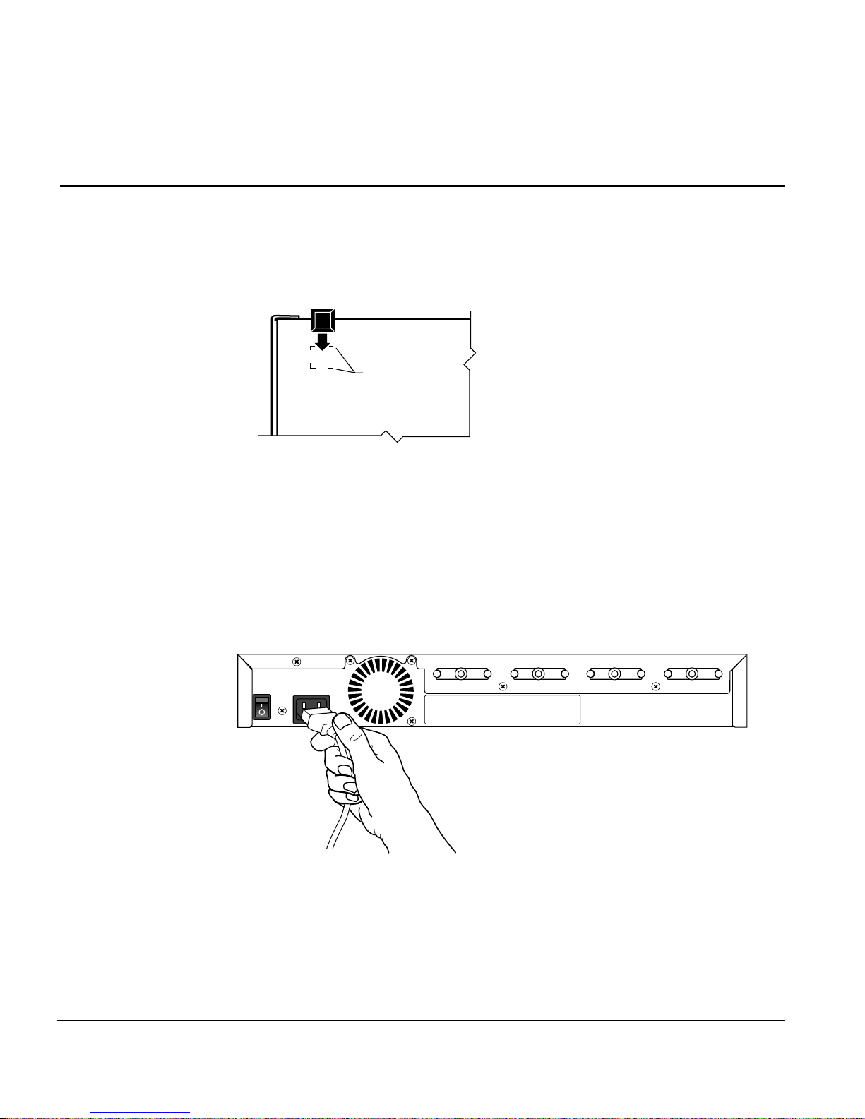
Table or Shelf Installation
To install the Model 281xSA hub on a table or shelf, follow these steps:
1. Peel off the protective backing from the rubber feet and apply one at
each marked location on the bottom of the hub (see Figure 2-2).
Figure 2-2. Attaching feet
Table or Shelf Installation
Feet placement
guides
4642
2. Set the hub on a table or shelf so that it has at least 2 inches of space
on all sides.
3. Connect the power cord, first to the power entry receptacle on the
back of the hub (see Figure 2-3) and then to the wall.
EXPANSION 2EXPANSION 3EXPANSION 4EXPANSION 5
4643
Figure 2-3. Connecting the power cord
893-743-A 2-5
Page 31

Installing the Model 281xSA Hub
4. Turn on the power switch.
5. Check the Power LED on the front panel (see Figure 2-4).
If this LED does not light, contact your customer support representative.
Expansion
23
µP FaultOn Line
Int
Power LED
Power
NM
Control
Isolate Data <Data> Col
AUI Port
AUI
Partition
MDI-X/MDI
4644
Figure 2-4. Power LED
At this point, the hub is ready to have the network cables connected. See
Chapter 3, “Network Configurations and Cable Connections,” for information
on completing the network installation.
2-6 893-743-A
Page 32

Rack Installation
Rack Installation
To install the Model 281xSA hub in an equipment rack, follow these steps:
1. Attach the mounting brackets.
a. On each side of the hub, use a #1 Phillips screwdriver to remove the
screws at the front corner (see Figure 2-5).
®
Remove
screws
Expansion
2345
Int
µP FaultOn Line
NM
Power
Isolate Data <Data> Col
Control
AUI Port
AUI
MDI-X/MDI
Partition
Reset
System Operation
Link Part
1234 56 78 910111213141516
RS-232 Service Port
MDI-X
4645
Figure 2-5. Attaching brackets for rack installation
b. Hold a mounting bracket against each side of the hub, as shown in
Figure 2-5, and align the countersunk screw holes in the bracket with
the bracket mounting holes in the hub.
The bracket covers a fe w of the chassis ventilation holes. This does not
compromise the cooling of the hub.
c. Insert two #4-40 x 5/16 flat-head screws through each bracket and into
the bracket mounting holes in the hub cabinet.
d. Using a #1 Phillips screwdriver, tighten the screws to secure each
bracket.
893-743-A 2-7
Page 33

Installing the Model 281xSA Hub
2. Install the hub in the rack.
a. Hold the hub with the mounting holes in the brackets aligned with
holes in the rack (see Figure 2-6).
µP FaultOn Line
Expansion
Int
2345
NM
Power
Control
Isolate Data (Data) Col
AUI Port
System Operation
Reset
Link Part
AUI
Partition
1 2 3 4 5 6 7 8 910111213141516
MDI-X/MDI
RS-232 Service Port
MDI-X
Figure 2-6. Installing the hub in an equipment rack
b. Insert two #10-32 x 3/4 pan-head screws with nylon washers through
each bracket and into the rack.
c. Using a #2 Phillips screwdriv er, tighten the screws to secure the hub to
the rack.
4646
2-8 893-743-A
Page 34

Rack Installation
3. Connect the power cord, first to the power entry receptacle on the
back of the hub (see Figure 2-7) and then to the power outlet.
EXPANSION 2EXPANSION 3EXPANSION 4EXPANSION 5
4643
Figure 2-7. Connecting the power cord
4. Turn on the power switch.
5. Check the Power LED on the front panel (see Figure 2-8).
If this LED does not light, contact your customer support representative.
Expansion
23
AUI
Partition
Int
MDI-X/MDI
4644
Power LED
Power
µP FaultOn Line
NM
Control
Isolate Data <Data> Col
AUI Port
Figure 2-8. Power LED
At this point, the hub is ready to have the network cables connected. See
Chapter 3, “Network Configurations and Cable Connections,” for information
on completing the network installation.
893-743-A 2-9
Page 35

Installing the Model 281xSA Hub
Wall Installation
In a wall installation, the Model 281xSA hub must be mounted on a wooden
surface. Make sure half-inch plywood is securely attached to the wall where
you intend to install the hub.
NOTE: You must supply four #12 x 5/8 pan-head Phillips sheet metal screws
for wall mounting the Model 281xSA hub.
To install the Model 281xSA hub on a wall, follow these steps:
1. Attach the mounting brackets.
a. Using a #1 Phillips screwdriver, remove the two bottom screws on
each side of the hub (see Figure 2-9).
®
et
or
Expansion
2345
Int
µP FaultOn Line
NM
Power
Isolate Data <Data> Col
Control
AUI Port
AUI
Partition
Reset
System Operation
Link Part
1234 567 8 910111213141516
MDI-X/MDI
RS-232 Service Port
MDI-X
Figure 2-9. Attaching brackets for wall mounting
b. Hold a mounting bracket against each side of the hub where you
removed the scre ws, as shown in Figure 2-9, and align the countersunk
screw holes in the bracket with the bracket mounting holes in the hub.
c. Insert two #4-40 x 5/16 flat-head screws through each bracket and into
the bracket mounting holes in the hub cabinet (see Figure 2-9).
d. Using a #1 Phillips screwdriver, tighten the screws to secure each
bracket.
Remove
screws
4647
2-10 893-743-A
Page 36

Wall Installation
2. Prepare the wall for installing the mounting screws.
a. Using Figure 2-10 as a guide, mark the mounting screw locations
on the plywood where you plan to install the hub.
b. Drill pilot holes at the marked locations.
7
17 "
8
5"
2002.2
Figure 2-10. Template for wall mounting
3. Holding the hub against the plywood, align the bracket holes with
the pilot holes in the wood.
4. Insert and tighten the sheet metal screws (see Figure 2-11).
893-743-A 2-11
Page 37

Installing the Model 281xSA Hub
2004.6
Figure 2-11. Securing the Model 281xSA hub to the wall
5. Connect the power cord, first to the power entry receptacle and then
to the wall outlet (see Figure 2-12).
EXPANSION 4EXPANSION 5
Figure 2-12. Connecting the power cord
2-12 893-743-A
4648
Page 38

Wall Installation
6. Turn on the power switch.
7. Check the Power LED on the front panel (see Figure 2-13).
If this LED does not light, contact your customer support representative.
Expansion
23
µP FaultOn Line
Int
Power LED
Power
NM
Control
Isolate Data <Data> Col
AUI Port
AUI
Partition
MDI-X/MDI
4644
Figure 2-13. Power LED
At this point, the hub is ready to have the network cables connected. See
Chapter 3, “Network Configurations and Cable Connections,” for information
on completing the network installation.
893-743-A 2-13
Page 39

Chapter 3 Network Configurations and Cable
Connections
This chapter provides general requirements and recommendations for proper
network configurations using the Model 281xSA Ethernet Hub. The chapter
summarizes the possible expansion of a network from a single-hub network to
one that encompasses several clusters and includes System 3000 equipment.
Single-hub, cluster, and multiple-hub networks are described, as well as
configuration rules for each type. Each network configuration description is
followed by instructions for making the cable connections necessary for that
configuration.
The installation procedures in this chapter assume that UTP horizontal
distribution cables are already installed, providing connection from the work
area wall outlet to the wiring closet punchdown blocks, and that cables are
properly identified. Normal cabling system practices are assumed; your
installation procedure may vary slightly, depending on your particular cabling
system.
This chapter includes the following topics:
■ A summary of how networks can expand from one hub to many
■ A description of a typical single-hub network, with instructions for
making the necessary cable connections
■ A description of the System 2000 cluster configuration and instructions
for connecting hubs into a cluster
■ Instructions for connecting multiple System 2000 hubs and clusters to
form a larger network
■ Examples of typical networks that use System 2000 and System 3000
equipment
893-743-A 3-1
Page 40

Network Configurations and Cable Connections
Building Network Configurations
The simplest type of System 2000 network is a small standalone network that
does not require SNMP-based network management. Starting with a single
Model 280x hub, you can connect a maximum of 16 10BASE-T stations to a
local Ethernet segment. Local hub management in the Model 280x hub
provides monitoring and control functions through an easy-to-use ASCII
terminal interface. As the number of users on the segment gro ws to greater than
16, multiple Model 280x hubs can be interconnected via the MDI-X/MDI
switchable port 1, or through the A UI or fiber backbone interconnect ports. (For
a description of how to use the MDI-X/MDI port, see Appendix B, “LEDs and
Switches.”) However , as the network grows, so does the need for management.
As you increase the station count, the ability to add SNMP management
support becomes increasingly important.
At this point, you can add a single Model 281xSA hub and connect up to four
Model 280x hubs through expansion ports, creating a Model 281xSA/280x hub
cluster . This arrangement pro vides Advanced Analyzer SNMP management for
all stations (up to 80) connected to the cluster. It also increases the number of
available ports in two ways:
■ This configuration adds the 16 ports on the Model 281xSA hub to the total
number of available ports.
■ The cluster frees the MDI-X/MDI ports on the hubs for station
connections (if you were formerly using the MDI-X/MDI ports for
interconnection).
Perhaps the most important feature of this cluster, in terms of future e xpansion
capabilities, is that by using the expansion ports to cluster the hubs, you have
reduced to one the number of repeaters in the cluster. The retiming function is
distributed among all units in the cluster, and the cluster operates in the
network as a single logical IEEE 802.3 repeater.
To increase the network size beyond 80 ports, you can begin interconnecting
the cluster to other hubs. Because System 2000 hubs are compatible with other
System 2000 and System 3000 products, they can be used to connect a
10BASE-T workgroup into a larger enterprise network. Clusters can serve as a
local workgroup in a very large network using larger hubs, or clusters
themselves can be interconnected. Clusters are treated like single hubs in these
configurations.
3-2 893-743-A
Page 41

Single-hub Network
A single-hub network using a Model 281xSA hub provides full SNMP
management for up to 16 10BASE-T Ethernet stations. Figure 3-1 shows such a
network configuration. In the work area, the Ethernet stations are attached to
the UTP horizontal distribution cables through the AUI network interface card
(NIC) and 10BASE-T transceivers. A management station is connected to a
host port. The maximum allowed length of the UTP cable to an Ethernet station
is 100 meters.
Single-hub Network
Model 2813SA
Ethernet Hub
SNMP management
station
Figure 3-1. Typical single-hub configuration
Ethernet Station Connections
For a single-hub network, the only cable connections are those between the
Ethernet stations and the hub. Ethernet station connections are standard for all
network configurations, irrespective of the number of hubs used, and are
typically made in two locations: in the work area and in the wiring closet.
AUI
cable
XCVR
UTP
wire
XCVRXCVR
UTP
wire
XCVR
= Workstation
= Model 508B transceiver
XCVR
cable
AUI
4649
893-743-A 3-3
Page 42

Network Configurations and Cable Connections
Cable Connections in the Work Area
The Ethernet station can have one of the following two types of network
interface card installed:
■ An AUI network interface card
■ A 10BASE-T network interface card
Using an AUI Network Interface Card
If you are connecting an Ethernet station with an AUI network interface card,
you must use an external 10BASE-T transceiver, such as the SynOptics Model
508B or 928 transceiver.
To connect the station to the premises cabling, follow these steps:
1. Connect the transceiver to the station.
a. If you are using a Model 508B 10BASE-T transceiver, attach an AUI
cable (for example, a Model 903A cable) from the interface card to the
AUI port of the Model 508B transceiver, as shown in Figure 3-2.
Figure 3-2. Connecting an AUI cable to a Model 508B 10BASE-T Transceiver
b. If you are using a SynOptics Model 928 integrated transceiver, attach
3-4 893-743-A
4650
the transceiver directly to the interface card (see Figure 3-3).
Page 43

2517
Single-hub Network
Figure 3-3. Connecting a Model 928 transceiver to a network station
2. Connect the cable between the transceiver and the wall outlet.
a. If you are using a Model 508B transceiver, connect a UTP patch cable
(for example, a Model 910 cable) from the RJ-45 port of the
transceiver to the RJ-45 connector of the wall outlet (see Figure 3-4).
2172.4
Figure 3-4. Connecting UTP cable to a Model 508B transceiver
893-743-A 3-5
Page 44

Network Configurations and Cable Connections
b. If you are using a Model 928 integrated transceiver, attach the captive
cable on the Model 928 transceiver to the wall outlet (see Figure 3-5).
Figure 3-5. Connecting the Model 928 transceiver to the wall
Wall connector
RJ-45 plug
4753
Repeat steps 1 and 2 for each type of station until all Ethernet stations are
connected to the UTP horizontal distribution cabling through the RJ-45
connectors of wall outlets.
Using a 10BASE-T Interface Card
If a 10BASE-T network interface card is installed in the Ethernet station, you
do not need the external 10BASE-T transceiver and AUI cable. To connect an
Ethernet station with a 10BASE-T network interface card, follow these steps:
1. Connect one end of a UTP patch cable (for example, a Model 910
cable) to the RJ-45 port of the 10BASE-T interface card
(see Figure 3-6).
3-6 893-743-A
Page 45

Single-hub Network
2013.10.4.2
Figure 3-6. Connecting a 10BASE-T interface card
2. Connect the other end to the RJ-45 connector of the wall outlet (see
Figure 3-6).
Repeat steps 1 and 2 for each type of station until all Ethernet stations are
connected to the UTP horizontal distribution cabling through the RJ-45
connectors of wall outlets.
NOTE: To connect Ethernet stations to IBM Type 1 STP cable, use the Model
822 10BASE-T-to-Type 1 Adapter. See the Model 822 10BASE-T-to-Type 1
Adapter Reference Sheet for installation details.
Cable Connections in the Wiring Closet
To complete the connection of each Ethernet station to a 10BASE-T host port
on the Model 281xSA hub, follow these steps:
1. Verify that the total UTP segment length (including building wires
and all patch cables used on any run between the station and the hub)
does not exceed 100 meters.
893-743-A 3-7
Page 46

Network Configurations and Cable Connections
2. Make sure the MDI-X/MDI switch on each Model 281xSA hub is set
to the MDI-X position (see Figure 3-7).
Expansion
2345
Int
System Operation
MDI-X/MDI
switch
(Data) Col
AUI
Partition
MDI-X/MDI
Link Part
12
4651.1
Figure 3-7. MDI-X/MDI switch set to the MDI-X position
The MDI-X/MDI switch is used to swap the pin assignments of the
transmit and receive data wire-pairs for port 1. If the remote end of the
wire is connected to a network station or to an MDI port on another hub,
use the MDI-X configuration. Ports 2 through 16 are internally configured
as MDI-X ports. See Appendix B, “LEDs and Switches,” for a more
complete description of the MDI-X/MDI switch operation.
3-8 893-743-A
Page 47

Single-hub Network
3. Connect a 25-pair UTP cable from the punchdown block to a UTP
patch panel (see Figure 3-8).
Punchdown
block with 50-pin
Model 2813SA
Ethernet Hub
telco connector
LattisHub 2813
10BASE-T Concentrator
UTP
patch
panel
50-pin
telco
connector
25-pair
cable
Equipment
rack
Wall
4652
Figure 3-8. Connecting 25-pair UTP cable
4. Connect one end of a UTP patch cable (for example, a Model 910
cable) to the UTP patch panel (see Figure 3-8).
893-743-A 3-9
Page 48

Network Configurations and Cable Connections
5. Connect the other end to a 10BASE-T port on the Model 281xSA hub
(see Figure 3-9).
UTP
cable
Figure 3-9. Model 281xSA hub 10BASE-T port connection
4653
6. Verify that the port Link LED is ON.
NOTE: The System 2000 Ethernet hubs support the 10BASE-T specified link
integrity test function. See Appendix D, “Link Integrity Test Function,” for a
complete description of this feature.
Repeat steps 1 through 6 until all Ethernet stations are connected to 10BASE-T
ports on the Model 281xSA hub.
See Appendix C, “Pin Assignments,” for the pin assignments of the RJ-45
connector on the Model 281xSA hub.
The System 2000 hubs support automatic polarity detection and correction,
which detects and automatically corrects for signal inversions on the UTP
receive data wire-pair. If any receive data wire-pair was mistakenly reversed in
the punchdown block during cable installation, the System 2000 hub internally
corrects for the miswiring, and the data path operates correctly. For more
information about this feature, see Appendix E, “Autopolarity Detection and
Correction.”
3-10 893-743-A
Page 49

Cluster Configurations
To add ports to a network made of a single Model 281xSA hub, or to add
network management to a network made of a single Model 280x hub, you can
create a Model 280x/281xSA cluster configuration. A cluster configuration (see
Figure 3-10) consists of one Model 281xSA hub and one or more attached
Model 280x hubs, up to a maximum of four Model 280x hubs. A cluster lets
you build the network from a starting point of 16 or fewer stations to a
maximum of 80 stations, and extend network management to all 80 stations.
Model 2813SA/280x cluster
Cluster Configurations
Punchdown block with 50-pin
telco connector
Model 988
expansion
cables
WIRING CLOSET
WORK AREA
LattisHub 2813
LattisHub 2803
LattisHub 2803
LattisHub 2803
LattisHub 2803
25-pair
UTP
patch
panel
Workstation
Equipment
rack
Workstation
cable
outlets
Figure 3-10. Typical Model 2813/2803 cluster configuration
Wall
Wall
2951.1
893-743-A 3-11
Page 50

Network Configurations and Cable Connections
Connection in a Model 281xSA/280x cluster is accomplished via Model 988
10BASE-T Workgroup Expansion Cables and the expansion ports on the hubs.
The Model 281xSA hub extends full SNMP functionality to the ports on the
Model 280x hub, providing up to 80 managed ports. Figure 3-10 shows a
typical cluster configuration network with four Model 2803 hubs connected to
the Model 2813SA.
NOTE: A cluster configuration requires one (and only one) Model 281xSA
hub, which supplies four expansion ports. These ports can be used to connect
any combination of Model 2803 and 2804 hubs to the Model 281xSA hub. You
cannot connect Model 280x hubs into a cluster without a Model 281xSA or
Model 281x hub.
Cluster Operation
A Model 281xSA/280x cluster configuration operates like a single-hub
network, with these two additional conditions:
■ Local hub management is disabled for any Model 280x hub connected to a
Model 281xSA hub through the expansion port.
■ Because of the nature of the expansion port connection, repeater
functionality is distributed among all the units in the cluster, and the
cluster becomes a single logical IEEE 802.3 Ethernet repeater.
If the Model 281xSA hub in a cluster loses power, the cluster configuration
stops operating as a cluster. It loses the SNMP management, and the Model
280x hubs become isolated 16-port segments. If any one of the Model 280x
hubs in a cluster loses power, the remaining hubs maintain the cluster
configuration.
Connecting a Cluster Configuration
In the work area, connections to the network station are the same as those
already described in the earlier section “Cable Connections in the Work Area.”
Follow the appropriate steps for either STP or UTP cable.
To connect the cluster configuration, follow these steps:
1. Connect the station cables to the hub host ports, as described earlier
in “Ethernet Station Connections.”
3-12 893-743-A
Page 51

Cluster Configurations
2. Connect the Model 280x hubs to the Model 281xSA hub, using the
Model 988 Expansion Cable that was shipped with each Model 280x
hub (see Figure 3-11).
a. Connect the DB-25 connector on one end of the expansion cable to the
expansion port on the Model 280x hub.
b. Connect the other end of the expansion cable to an av ailable expansion
port on the Model 281xSA hub. At this point, if the hub power is on,
one LED lights on each hub, as follows:
■ The Expansion Status LED on the Model 281xSA hub lights.
■ The associated Expansion LED on the Model 280x hub lights.
EXPANSION 2EXPANSION 3EXPANSION 4EXPANSION 5
Model 281xSA
hub
TERMINAL PORT
TERMINAL PORT
TERMINAL PORT
TERMINAL PORT
Figure 3-11. Connecting a cluster configuration
EXPANSION
EXPANSION
Model 280xSA
hub
EXPANSION
EXPANSION
4655
893-743-A 3-13
Page 52

Network Configurations and Cable Connections
Multiple-hub Networks—System 2000 Only
Individual System 2000 hubs or Model 280x/281xSA cluster configurations
can be interconnected through a backbone interconnection or through the
MDI-X/MDI ports. Backbone connections are made through the interconnect
port, either the AUI port (Model 2813SA hub) or the 10BASE-FL port
(Model 2814SA hub).
Configuration Rules
When you install a network with more than one hub, you must follow these
configuration rules:
■ Make sure all UTP segments are no longer than 100 meters.
■ Disable the signal quality error (SQE) test function on the transceiver
connected to the AUI port of the Model 2813SA hub.
■ Y ou can hav e a maximum of four hubs (repeaters) in the data path between
any two Ethernet stations. (Remember that a cluster counts as only a
single repeater.) To extend the network further, use a bridge or router.
■ To use port 1 as an interconnect port to an MDI-X port on another hub,
you must configure it as an MDI port, using the MDI-X/MDI switch.
Interconnecting Model 2813SA Hubs Using the AUI Port
You can connect the AUI port on the Model 2813SA hub to any mediumspecific IEEE 802.3 MAU. For example, you can use an IEEE 802.3
10BASE-FL fiber optic medium attachment unit (FOMAU), such as the
SynOptics Model 504A transceiver, to connect the Model 2813SA hub to
a fiber optic port on another hub. You can also connect the Model 2813SA
hub AUI port to a coaxial backbone through an IEEE 802.3 MAU.
Although the example that follows shows connection between Model 2813SA
hubs and fiber optic cable through transceivers, the simpler way to connect to a
fiber backbone is by using Model 2814SA hubs, with their integral
10BASE-FL ports.
3-14 893-743-A
Page 53

Multiple-hub Networks—System 2000 Only
Connecting the AUI Port to a Fiber Backbone
Connecting an IEEE 802.3 10BASE-FL transceiver to the AUI port on the
Model 2813SA hub allows you to connect the Model 2813SA hub to a fiber
backbone. Figure 3-12 shows a typical network with two Model 2813SA hubs
connected to a fiber backbone. An AUI patch cable connects each Model
2813SA hub to a SynOptics Model 504A transceiver that has the SQE test
disabled. A fiber optic cable is connected between the two transceivers.
Model 2813SA Ethernet Hub
LattisHub 2813SA
AUI cable
Fiber
optic
cable
AUI cable
IEEE 802.3 10BASE-FL transceiver
(for example, Model 504B Transceiver)
UTP cables
to Ethernet
stations
Model 2813SA Ethernet Hub
LattisHub 2813SA
Figure 3-12. Interconnecting Model 2813SA hubs using an IEEE 802.3
10BASE-FL transceiver
4656
893-743-A 3-15
Page 54

Network Configurations and Cable Connections
To use an IEEE 802.3 10BASE-FL transceiver to interconnect the
Model 2813SA hub and other hubs, follow these steps:
1. Disable the SQE test on an IEEE 802.3 10BASE-FL transceiver
(for example, a Model 504A transceiver).
NOTE: The IEEE 802.3 rules require you to disable the SQE test function
on the IEEE 802.3 10BASE-FL transceiver connected to the AUI port of the
Model 2813SA hub.
2. Connect an AUI cable between the AUI port on the Model 2813SA
hub and the AUI port on the transceiver.
3. Connect a fiber optic cable between the transceiver and another
optical port (for example, a port on a Model 3304A Host Module
in a Model 3000 Concentrator) at the next higher level in the network
hierarchy.
Repeat steps 1 through 3 for each Model 2813SA hub that is to be interconnected through an IEEE 802.3 transceiver.
Connecting the AUI Port to Coaxial Backbone
You can use the AUI port to connect a Model 281xSA hub to a coaxial
backbone through an IEEE 802.3 MAU. Figure 3-13 shows a Model 2813SA
hub and a Model 2803/2813SA cluster connected to a coaxial backbone
through IEEE 802.3 MAUs. An AUI cable is connected between the AUI port
on each Model 28x3 hub and the MA U. The SQE test is disabled on each MAU
connected to the AUI port on a Model 28x3 hub.
NOTE: The IEEE 802.3 rules require you to disable the SQE test function on
an IEEE 802.3 MAU connected to the AUI port of the Model 28x3 hub.
3-16 893-743-A
Page 55

Multiple-hub Networks—System 2000 Only
termination
AUI
port
Model
2813SA
hub
Model
2803
hubs
50-ohm
IEEE 802.3 MAU IEEE 802.3 MAU
AUI
port
AUI
cable
Model 281xSA/280x cluster
XCVR
XCVR
LattisHub 2813
Coaxial backbone
Model 2813SA Ethernet Hub
XCVR
AUI cable
XCVR
50-ohm
termination
LattisHub 2813
XCVRXCVR
= Workstation
= Model 508B transceiver
XCVR
SNMP management
station
4657
Figure 3-13. Interconnecting Model 281xSA hubs using coaxial backbone
To connect a Model 2813SA hub to a coaxial backbone, follow these steps:
1. Disable the SQE test on the IEEE 802.3 MAU.
2. Connect the MAU to the coaxial backbone.
3. Connect an A UI cable between the IEEE 802.3 MA U and the AUI port
on the Model 2813SA hub.
Repeat steps 1 through 3 for each Model 2813SA hub that is to be connected to
the coaxial backbone.
893-743-A 3-17
Page 56

Network Configurations and Cable Connections
Interconnecting Model 2814SA Hubs Using the 10BASE-FL Port
Figure 3-14 shows two Model 2814SA hubs connected via their 10BASE-FL
fiber ports. A fiber cable is connected directly between the ports on the two
hubs; TX on each hub is connected to RX at the other end.
Model 2814SA Ethernet Hub
LattisHub 2814SA
Fiber optic cable
Model 2814SA Ethernet Hub
LattisHub 2814SA
UTP cables to
Ethernet stations
4658
Figure 3-14. Connecting Model 2814SA hubs using the 10BASE-FL port
The fiber interface of the Model 2814SA hub is compatible with the latest IEEE
802.3 10BASE-FL draft standard, as well as fully compatible with the IEEE
fiber optic inter-repeater link (FOIRL) standard. The fiber interconnect ports on
the Model 2814SA hub support up to 2-kilometer distances using
62.5/125 µm core/cladding multimode optical fiber.
To connect two Model 2814SA hub 10BASE-FL ports, follow these steps:
1. Make sure the power is on for both hubs.
2. Connect one end of a fiber cable to the ST connectors on one
Model 2814SA hub 10BASE-FL port.
3. Connect the other end of the fiber cable to the other Model 2814SA
hub 10BASE-FL port.
4. Check the Link LED for each port. If it is not lit, reverse the TX
and RX connectors on one end of the cable.
3-18 893-743-A
Page 57

Interconnecting Hubs Using the MDI Port 1
You can interconnect Model 281xSA hubs by connecting an MDI port 1
on one Model 281xSA hub to any MDI-X 10BASE-T port on another hub.
Figure 3-15 shows such a configuration, in which two Model 280x/2813SA
clusters are connected to a Model 2813SA hub. Port 1 on each cluster
Model 2813 hub is set to MDI, and a UTP patch cable is used to connect
each of these ports to an MDI-X port on the higher Model 2813SA hub.
NOTE: Interconnections through the MDI-X/MDI ports must always be from
MDI to MDI-X. Ports 2 through 16 are internally configured as MDI-X ports,
and the switchable port 1 is factory-set to be an MDI-X port. If you interconnect two Model 281xSA hubs through port 1 on both hubs, you must change
one port (but only one) to the MDI setting.
Multiple-hub Networks—System 2000 Only
MDI-X (ports 2-16)
Switch set
to MDI
Model 2813SA hub
Model 2803 hubs
Figure 3-15. Interconnecting hubs via the MDI port
To use the MDI port 1 for interconnecting hubs, follow these steps:
Model 2813SA
Ethernet Hub
UTP cable
LattisHub 2813SA
UTP cable
Switch set
to MDI
LattisHub 2813SA LattisHub 2813SA
UTP cables to
Ethernet stations
4659
1. Use a small flat-blade screwdriver to set the MDI-X/MDI switch on
a Model 281xSA hub to the MDI position (see Figure 3-16). This
adjustment sets port 1 as an MDI port.
893-743-A 3-19
Page 58

Network Configurations and Cable Connections
Expansion
2345
Int
System Operation
MDI-X/MDI
switch
(Data) Col
AUI
Partition
MDI-X/MDI
Link Part
12
4651
Figure 3-16. MDI-X/MDI switch set to MDI
2. Connect the MDI port 1 of the Model 281xSA hub to any MDI-X
10BASE-T port on a hub at the next higher level in the network
hierarchy.
Repeat steps 1 and 2 for each Model 281xSA hub that is to be interconnected
through an MDI port 1 to another hub.
Multiple-hub Networks—Including System 3000 Products
The Model 281xSA Ethernet Hubs readily interconnect with SynOptics System
3000 products, using the same cabling procedures already described. You can
connect a Model 2813SA hub AUI port through a MAU or FOMAU to a host
port on a System 3000 concentrator, or you can connect a Model 2814SA hub
10BASE-FL port directly to an optical port located in a System 3000 concentrator. For detailed information about networks using System 3000 equipment,
see the LattisNet System 3000 Ethernet Connectivity Guide.
Figure 3-17 shows a typical network that combines a Model 3000 concentrator
with a Model 281xSA hub and a Model 281xSA/280x cluster. Both the single
hub and the cluster are connected to host ports on a Model 3304-ST Host
Module in the Model 3000 concentrator.
3-20 893-743-A
Page 59

Multiple-hub Networks—Including System 3000 Products
Model 3304A
host module
Model 3000 concentrator
Model 3314SA
Network
Management
Module
Model 504-ST transceiver)
AUI cable
IEEE 802.3 FOMAU
(for example,
Fiber
optic
cable
IEEE 802.3 FOMAU
(for example, Model 504-ST transceiver)
AUI cable
Model 2813SA Ethernet Hub
Model 2813SA Ethernet Hub
UTP cables to
Ethernet stations
4661
Figure 3-17. Network including a Model 3000 concentrator
You can also substitute a Model 281xSA/280x cluster for the Model 3000
concentrator shown in Figure 3-17. Figure 3-18 shows such a network in which
a Model 2814SA/2804 cluster serves as the central point for the star-wired
configuration. Clusters are interconnected through the fiber interconnect ports.
893-743-A 3-21
Page 60

Network Configurations and Cable Connections
Model 2814SA
Ethernet Hub
Model 2804 hubs
Model 2814SA
Ethernet Hub
Model 281xSA hub cluster
LattisHub 2814SA
Fiber optic
cables
Model 2814SA Ethernet Hub
LattisHub 2814SA
Model 281xSA hub cluster
LattisHub 2814SA
Model 2804 hubs
UTP
cables to
Ethernet
stations
4662
Figure 3-18. Fully manageable network composed entirely of Model 281xSA
clusters and single hubs
3-22 893-743-A
Page 61

Chapter 4 Configuring the Model 281xSA Hub for
IP/IPX Networks
This chapter provides instructions for configuring the Model 2813SA and
2814SA Ethernet Hubs for networks that use IP, IPX, or a combination of
the two.
Required Network Information and Configuration Actions
To manage the Model 281xSA hub in an IP or IPX network environment, you
must have the hardware address of the Model 281xSA hub set up in the IP or
IPX load server configuration file. The hardware address consists of 000081
followed by the number printed on the address label on the 281xSA front panel
(see Figure 4-1). For instructions on setting up the configuration file, see
Appendix G, “Setting Up the Model 281xSA Hub Configuration File,” and
refer to the documentation that shipped with your load server.
14 15 16
Hardware
address label
4663
Figure 4-1. Hardware address label
On a network managed through IP network management (with or without IPX),
the Model 281xSA hub requires a BootP server or requires configuration
through the service port. The following sections explain IP and IPX configuration options. “Connecting to the Model 281xSA Service Port,” later in this
chapter, explains how to connect a suitable terminal to the Model 281xSA
service port.
On a network managed exclusively through IPX network management, the
Model 281xSA hub does not need a BootP server or service port configuration.
The hub obtains the basic required IPX network information automatically
from the other IPX entities on the network.
893-743-A 4-1
Page 62

Configuring the Model 281xSA Hub for IP/IPX Networks
IP/IPX and BootP Network Configuration Options
The configuration process for the Model 281xSA hub depends on the network
management protocol and on whether or not the network has an operating
BootP server. The following four circumstances are typical:
■ If the network is IP based and lacks a BootP server, you must configure the
Model 281xSA hub through a terminal connected to the Model 281xSA
service port. For instructions on configuring the Model 281xSA hub
through the service port, see the section “Setting the Boot Configuration
without a BootP Server” later in this chapter.
■ If the network is IP based and has a BootP server, you do not need to
configure the Model 281xSA hub through a terminal connected to the
service port, provided that you first modify the load server configuration
file, BOOTPTAB.TXT, and the Model 281xSA configuration file. The
Model 281xSA configuration file should be installed on the load server
as specified in the publications that came with load server or network
management software. Text for the Model 281xSA configuration file and
file parameter descriptions are given in Appendix G, “Setting Up the
Model 281xSA Hub Configuration File.”
■ If the network is IPX based, you do not configure the Model 281xSA hub
manually through the service port because the hub automatically obtains
required IPX network information from the network.
■ If the network uses both IP and IPX, you may need to configure the Model
281xSA hub for IP operation through the service port if no BootP server is
operating on the network. For the IPX portion of the network, configuration through the service port is not necessary.
4-2 893-743-A
Page 63

Using the Service Port
You can connect a terminal to the service port either before you turn on the
power to the hub or while the hub is operating. Attaching a terminal allows you
to view system startup diagnostics or to configure the hub.
When the Model 281xSA hub receives power, it runs self-test diagnostics and
reports the results to the service port. If you have a standard RS-232 character
terminal connected to the port (as explained in the following section), you can
observe the diagnostic messages as the hub boots or goes through a reset.
Terminal Connection Requirements
To connect a terminal to the service port, you need the following two items:
■ An ASCII character terminal that has an RS-232 serial port or a computer
that has an RS-232 serial port and terminal emulation, typically a PC
running common communications software
Using the Service Port
■ A standard RS-232 serial communications cable with a DB-9 socket at
one end for connection to the service port and an appropriate connector,
usually a DB-9 or DB-25 plug, at the other end for connection to the serial
port on the terminal or terminal emulator
Check the service port pin assignment in Appendix C, “Pin Assignments,” to
ensure correct connections between the service port and the terminal.
Connecting to the Model 281xSA Service Port
To connect the terminal or terminal-emulating computer to the Model 281xSA
service port, follow these steps:
1. Connect the RS-232 cable DB-9 receptacle to the service port plug.
2. Connect the other end of the RS-232 cable to the terminal or
terminal-emulating computer RS-232 serial port.
3. Turn on the power to the terminal or make sure the computer is
running in terminal emulation mode.
4. Put the terminal (or emulator) into configuration mode and set the
terminal parameters to the following settings:
9600 baud
8 data bits
No parity
893-743-A 4-3
Page 64

Configuring the Model 281xSA Hub for IP/IPX Networks
1 stop bit
No handshaking
ASCII code
5. Put the terminal (or emulator) online; do not leave it in configuration
mode.
The terminal screen is ready to display the messages sent from the
Model 281xSA service port, such as the results of the self-diagnostic tests
that run automatically after the hub is reset or the power is turned on.
To prepare the Model 281xSA hub for configuration or to view the service
port messages from the Model 281xSA hub, perform the next step.
6. Reset the hub or cycle the power to the Model 281xSA hub.
Watch the output display (see the next section) as the hub completes its
self-test diagnostics.
4-4 893-743-A
Page 65

Power-on Self-test Diagnostic Messages Display
Power-on Self-test Diagnostic Messages Display
The Model 281xSA hub performs a diagnostic self-test that checks its hardware
components during system startup. W ith a terminal attached to the service port,
diagnostic messages are displayed on the terminal screen (see Figure 4-2).
Model 281xSA Boot PROM Revision A, Mar 11 1994
Hit [ESC] to bypass memory tests
EPROM checksum test: PASSED
System DRAM #1 test: BYPASSED
System DRAM #2 test: BYPASSED
NVRAM test: PASSED
FLASH test: PASSED
Nic Ram Test: BYPASSED
DCE #1 LAN Interface test: PASSED
Initializing CNMI…Completed.
Set Partition Status…Completed.
4754
Figure 4-2. Diagnostic messages for the Model 281xSA hub
If an error occurs, the self-test loops to the point of the error. If the error
persists, the Model 281xSA hub resets itself and restarts. If the same error
message repeatedly displays on the monitor, or if the Fault LED remains lit,
contact your supplier’s customer service department.
893-743-A 4-5
Page 66

Configuring the Model 281xSA Hub for IP/IPX Networks
If the error clears, the diagnostics continue and the hub LEDs light as follows:
■ Power LED—on
■ On Line LED—flashing
■ NM Control—LED off
■ Fault LED—off
After completing its diagnostics, the Model 281xSA hub continues
automatically, trying to find the BootP server that has its configuration
parameters. Figure 4-3 shows an example of the service port screen during a
BootP sequence.
Model 281xSA Code Downloading Starting
Type [Ctrl] + C to go to Boot Main Menu
DCE#1 trying BOOTP
4755
Figure 4-3. BootP service port screen display
T o stop the automatic process and access the Model 281xSA boot configuration
menus, press
[Ctrl]+C. See “Setting the Boot Configuration without a BootP
Server” later in this chapter.
4-6 893-743-A
Page 67

Summary of the Boot Sequence with a BootP Server
Summary of the Boot Sequence with a BootP Server
This section summarizes the Model 281xSA hub boot sequence if a BootP
server is present and the boot file, BOOTPTAB.TXT, and Model 281xSA
configuration file, 281sa100.cfg, are correctly configured on the load server.
Given these conditions, you need not manually configure the Model 281xSA
hub via the service port; the hub automatically obtains its IP configuration
parameters via the BootP server and obtains its IPX parameters via the IPX file
server.
The factory default settings for the Model 281xSA hub are:
■ Boot Mode = Network
■ Boot Protocol = Auto
■ Image Load Mode = Remote w/Local
■ Management protocol = IP_IPX
■ Configuration load mode = Remote w/Local
■ Read community = public
■ Write community = private
The first time the Model 281xSA hub is powered on, it uses these settings to
perform the following boot sequence:
1. The Model 281xSA hub performs a diagnostic self-test and displays the
results on the terminal screen connected to the service port (if one is
connected).
2. The screen connected to the service port displays the message:
DCE#1 Trying BOOTP...
while the Model 281xSA hub sends a broadcast message looking for its
booting parameters.
3. The BootP server sends the booting parameters to the Model 281xSA hub.
4. If there is no response from the BootP server, the Model 281xSA hub
issues IPX “Find Nearest Server” SAP (service access protocol) frames to
learn the IPX network number. The connected screen displays:
DCE#1 Trying SAP...
893-743-A 4-7
Page 68

Configuring the Model 281xSA Hub for IP/IPX Networks
5. If a Novell server or IPX router is running on the network, it responds to
the SAP request. If the SAP request is not answered, the Model 281xSA
hub retries the BootP sequence.
6. Using ASCII mode TFTP, the server downloads the configuration file
(as specified by the boot parameters) to the Model 281xSA hub DRAM.
7. Via binary mode TFTP, the server transfers the run-time image file (as
specified by the configuration file or service port) to the Model 281xSA
hub. The terminal screen (if connected to the service port) displays the
SynOptics banner.
8. If the transferred code is different from that already in the flash EPROM,
the new run-time code is saved into flash EPROM.
9. The Model 281xSA run-time image file begins execution. The green
On Line LED of the Model 281xSA hub is on, and the yellow µP Fault
LED is off, indicating normal operation.
NOTE: If the downloaded image is different from what is already saved in
flash EPROM, flash EPROM is updated after that remote download.
Setting the Boot Configuration without a BootP Server
On some networks, a BootP server is not available to support the 281xSA
SNMP network management agent or a configuration file other than the default
configuration shown in Appendix G, “Setting Up the Model 281xSA Hub
Configuration File. ” If your Model 281xSA hub is connected to such a netw ork
and you use IP management, you must configure your Model 281xSA hub
manually by using the service port. This section describes the Model 281xSA
hub configuration and boot sequence, initial steps to make the hub ready for
configuration, and the configuration menus and commands.
To configure the Model 281xSA hub through the service port, you use the
configuration menus displayed on the terminal connected to the service port.
The Boot main menu tells the hub how to identify itself to the network
management software. You can access this menu only before the hub starts to
load the image code, as explained in the following procedure.
4-8 893-743-A
Page 69

Setting the Boot Configuration without a BootP Server
To set the boot configuration, follow these steps:
1. Connect a terminal to the hub service port, as described in
“Connecting to the Model 281xSA Service Port” earlier in this
chapter.
2. Turn on the power to the Model 281xSA hub; if it is already powered,
press the Reset button on the front panel.
3. Press [Ctrl]+C while the hub is attempting its boot processes and the
screen reads “DCE#1 trying BOOTP...” This allows you to access the
Boot main menu (shown in Figure 4-4)
.
Boot Main Menu 281xSA Ethernet NMM
MAC Address: 00:00:81:xx:xx:xx
Boot Mode:
Boot Protocol:
Management Protocol:
m
-Toggle boot mode
p
-Toggle boot protocol
t
-Toggle management protocol
i
-Toggle image load mode
f
-Toggle config file load mode
k
-Reset NVRAM to factory defaults
z
-Reset management module
Network
Auto
IP_IPX
Image Load Mode: Remote w/local
Config Load Mode: Remote w/local
c
|
-System configuration menu
b
|
-Boot file configuration menu
j
|
-IP configuration menu
x
|
-IPX configuration menu
e
|
-Load and execute boot files
g
|
-Perform power-up boot load sequence
w
|
-Write boot config to NVRAM
Figure 4-4. Boot main menu
4. Set the hub IP network address, as follows:
a. Press j to display the IP Configuration menu.
4756
b. Press i to display the Set IP Address prompt.
c. Enter the Model 281xSA hub IP address.
893-743-A 4-9
Page 70

Configuring the Model 281xSA Hub for IP/IPX Networks
5. Press [Esc] to return to the 281xSA Boot main menu.
6. Press f [Toggle config load mode] once to set the configuration load
mode to Local.
7. Press m [Toggle boot mode] to set the boot mode to NVRAM.
8. Press i [Toggle image load mode] to set the image load mode to Local.
9. Press w [Write boot configuration to NVRAM] to save the booting
parameters to NVRAM.
10. Press e [Load and execute boot files] to restart the hub.
As the hub goes through the booting process, messages are displayed on
the screen, as shown in Figure 4-5 and Figure 4-6.
DCE#1 TFTP (NETASCII) to load the config file s281xsa.cfg
Config file loaded
DCE#1 TFTP (OCTET) to load the image file s281xsa.img
Image file loaded
Images in DRAM and FLASH are different. Begin writing image to FLASH
Erasing FLASH …… Erased FLASH …
Programming FLASH …
Saved image to FLASH
* * * * * * * * * * * * * * * * * * * *
Copyright (c) 1994
*
SynOptics Communications, Inc.
*
All Rights Reserved
*
Date: Mar 14 1994, Time: 17:38:02
*
Model 281xSA Version 1.0.0
*
* * * * * * * * * * * * * * * * * * * *
Press CTRL-Y to begin
*
*
*
*
*
*
*
4757
Figure 4-5. Boot messages (remote image file load)
4-10 893-743-A
Page 71

Setting the Boot Configuration without a BootP Server
Image file loading from FLASH …… Loaded image
* * * * * * * * * * * * * * * * * * * *
Copyright (c) 1994
*
SynOptics Communications, Inc.
*
All Rights Reserved
*
Date: Mar 14 1994, Time: 17:38:02
*
Model 281xSA Version 1.0.0b
*
* * * * * * * * * * * * * * * * * * * *
Model type/revision: 281xSA/0
Press Ctrl-Y to begin
*
*
*
*
*
*
*
4758
Figure 4-6. Boot messages (local image file load)
At this point, the Model 281xSA hub is completely operational and requires
no user intervention. If you want to change any run-time parameters, press
[Ctrl]+Y to display the run-time parameters menu. This menu and associated
submenus are described in later sections of this chapter.
NOTE: If you plan to manage your network only with IPX network
management stations, BootP server or service port configuration is
unnecessary. The Model 281xSA hub automatically obtains the required IPX
network information from the network.
893-743-A 4-11
Page 72

Configuring the Model 281xSA Hub for IP/IPX Networks
Using Configuration Menus
To configure the Model 281xSA hub through the service port, you use
configuration menus on the display of the terminal connected to the service
port. There are two series of configuration menus:
■ One menu series (see Figure 4-7) sets the primary boot configuration; that
is, it tells the hub how to identify itself to the network management
software. You can access this menu only before the image code is loaded.
To access this menu, press [Ctr]+C.
■ The other menu series (see Figure 4-8) modifies the run-time parameters;
use the menus to change operating parameters as the hub is running. You
can access these menus only after the image code is loaded. To access
these menus, press [Ctr]+Y.
-Ctrl C
Toggle boot mode
Toggle boot protocol
Toggle management protocol
Toggle image load mode
Toggle config file load mode
Reset NVRAM to factory defaults
Reset management module
System configuration menu
Boot file configuration menu
IP configuration menu
IPX configuration menu
Load and execute boot files
Perform power-up bootload sequence
Write boot configuration to NVRAM
Toggle all RAM tests
Return to Boot main menu
Set server's IP address
Set boot router's IP address
Set config file name
Set image file name
Get config file info from network
Return to Boot main menu
Set IP address
Set subnet mask
Set default gateway
Get IP information from network
Return to Boot main menu
Get Network Number via network
Set Network Number
Return to Boot main menu
4759
Figure 4-7. Primary boot configuration menus
4-12 893-743-A
Page 73

-Ctrl Y
Using Configuration Menus
Set protocol parameters
Set SNMP parameters
Set out-of-band parameters
Set profile parameters
Set boot parameters
Set security parameters
Write values to EEPROM
Exit
Restart 281xSA
Reset 281xSA
(takes 45 seconds)
Set IP parameters
Set IPX parameters
Toggle management protocol
Return to main menu
Set read community
Set read/write community
Toggle authentication traps
Set IP trap receivers
Set IPX trap receivers
Return to main menu
Set baud rate
Set initialization string
Return to main menu
Set location
Set name
Set contact
Return to main menu
Toggle boot mode
Toggle boot protocol
Toggle image load mode
Toggle config load mode
Return to main menu
Set my IP address
Set subnet mask
Set default router's IP address
Set secondary default router's IP address
Set boot router's IP address
Set boot server's IP address
Set boot file name
Return to Protocol Parameter menu
Set network number
Return to Protocol Parameter menu
Figure 4-8. Run-time parameters menus
Menus for configuring the Model 281xSA hub have similar formats. Each
menu shows the current settings for a group of parameters, followed by a list
of commands for changing the parameters (see Figure 4-9 for an example).
893-743-A 4-13
Set security level
Toggle security configuration lock
Return to main menu
4760
Page 74

Configuring the Model 281xSA Hub for IP/IPX Networks
Boot Main Menu 281xSA Ethernet NMM
MAC Address: 00:00:81:xx:xx:xx
Commands
Boot Mode:
Boot Protocol:
Management Protocol:
m
-Toggle boot mode
p
-Toggle boot protocol
t
-Toggle management protocol
i
-Toggle image load mode
f
-Toggle config file load mode
k
-Reset NVRAM to factory defaults
z
-Reset management module
Network
Auto
IP_IPX
Image Load Mode: Remote w/local
Config Load Mode: Remote w/local
Figure 4-9. Sample configuration menu
c
-System configuration menu
b
-Boot file configuration menu
j
-IP configuration menu
x
-IPX configuration menu
e
-Load and execute boot files
g
-Perform power-up boot load sequence
w
-Write boot config to NVRAM
4756
Some commands switch between two or three possible settings; these
commands toggle a condition. Other commands allow you to enter information;
these commands set, add, or delete a parameter value. Specific commands on
the main menu shift the display to other menus from which you can select
additional commands.
To use the menus, follow these steps:
1. Press the key for the letter of the command you want to issue.
If you select a toggle command, the specified parameter changes its setting
in the upper part of the menu.
4-14 893-743-A
Page 75

If you select a set, add, or delete command, either the display shifts to a
submenu or the command you selected displays at the bottom of the menu,
followed by a type-in field. When a command selection displays a type-in
field, enter the requested information.
2. Repeat step 1 if you want to change other parameters.
3. If you are working from a submenu, press [Esc] when you are
finished. If you are working from the main menu, choose an
appropriate command from the command list.
Boot Configuration Menus
To set the primary boot configuration without a BootP server, press [Ctrl]+C
during the boot process to display the menu shown in Figure 4-10.
Boot Configuration Menus
Boot Main Menu 281xSA Ethernet NMM
MAC Address: 00:00:81:xx:xx:xx
Boot Mode:
Boot Protocol:
Management Protocol:
m
-Toggle boot mode
p
-Toggle boot protocol
t
-Toggle management protocol
i
-Toggle image load mode
f
-Toggle config file load mode
k
-Reset NVRAM to factory defaults
z
-Reset management module
Network
Auto
IP_IPX
Image Load Mode: Remote w/local
Config Load Mode: Remote w/local
c
|
-System configuration menu
b
|
-Boot file configuration menu
j
|
-IP configuration menu
x
|
-IPX configuration menu
e
|
-Load and execute boot files
g
|
-Perform power-up boot load sequence
w
|
-Write boot config to NVRAM
Figure 4-10. Boot main menu
893-743-A 4-15
4756
Page 76

Configuring the Model 281xSA Hub for IP/IPX Networks
The commands in this menu are of four types:
■ The m, p, t, i, and f commands set values for the parameters at the top
of the menu.
■ The j and x commands open submenus that configure the IP and IPX
operating parameters.
■ The k, z, e, g, and w commands initiate an action by the Model 281xSA
hub.
■ The c and b commands open submenus to configure the Model 281xSA
hub for booting.
To change a parameter value in the top section of the menu, type the letter that
corresponds to the parameter you want to change. Then type the new entry for
that item. To initiate one of the actions, simply type the letter of the desired
command.
See “Boot Configuration Commands” for a complete description of all the boot
configuration commands on the Boot main menu.
Boot Configuration Commands
The Boot main menu includes the following commands:
m [Toggle boot mode] Shifts the boot mode between Network
and NVRAM. The factory default setting is Network.
When Network is selected, the Model 281xSA hub tries to acquire
its configuration over the network, using the protocol specified by
the p command [Toggle boot protocol].
When NVRAM is selected, the Model 281xSA hub configures
itself during power-on or reset using the parameter v alues obtained
from the NVRAM (if they exist).
NOTE: When NVRAM is selected as the boot mode, you must use
the menu selections to set or change the required parameters.
p [Toggle boot protocol] Shifts the boot protocol among Auto, IP,
IPX, and IP_IPX. The factory default setting is Auto.
4-16 893-743-A
Page 77

Boot Configuration Menus
NOTE: If m [Toggle boot mode] is set to NVRAM, this parameter
is ignored.
When Auto is selected, the Model 281xSA hub tries to find its IP
or IPX configuration parameters over the network. This process
has two stages:
■ First the Model 281xSA hub seeks the IP parameters and
configuration file from a BootP server, transfers the configuration file, and writes the values (if it finds them) into
NVRAM. (Without IP parameters stored in NVRAM, this
Model 281xSA hub cannot be managed by IP.)
■ Then the Model 281xSA hub seeks the IPX parameters and
configuration file from a Novell server and writes the values
into NVRAM.
As long as it can find either IP or IPX parameters, the Model
281xSA hub writes the values into NVRAM. If the Model 281xSA
hub fails to locate either an IP BootP server or a Novell (IPX)
server or router, it resets and starts over.
When IP is selected, the Model 281xSA hub tries to locate a BootP
server and load the IP parameter values. It also writes these values
into NVRAM. If it cannot find a BootP server or transfer the
configuration file, it times out and returns to the Boot main menu
without obtaining a network address. If IP is selected, the Model
281xSA hub does not look for IPX parameters.
When IPX is selected, the Model 281xSA hub looks for a Novell
server or router from which it can obtain the IPX network number.
If no server or router responds, the Model 281xSA hub returns to
the Boot main menu. When IPX is selected, the Model 281xSA
hub does not look for a BootP server.
When IP_IPX is selected, the Model 281xSA hub looks for both
a BootP server (to provide the IP parameters) and a Novell server
or router (to provide the IPX parameters). First the Model 281xSA
hub looks for a BootP server. If it finds a BootP server, the hub
893-743-A 4-17
Page 78

Configuring the Model 281xSA Hub for IP/IPX Networks
downloads the configuration file without continuing to seek an IPX
address. If the hub cannot find a BootP server , it looks for a Nov ell
server or router. If it finds one, it transfers the configuration file,
obtains the IPX network number, and writes the parameter values
into NVRAM. If it fails to find IP parameters, the Model 281xSA
hub resets itself and starts the booting process over.
t [Toggle management protocol] Shifts the management protocol
among IP_IPX, IP, and IPX. The factory default setting is IP_IPX.
The management protocol is independent of the boot protocol.
When IP_IPX is selected, the Model 281xSA hub can be managed
by either IP or IPX network management stations.
When IP is selected, the Model 281xSA hub can be managed only
by IP network management stations.
When IPX is selected, the Model 281xSA hub can be managed
only by IPX network management stations.
NOTE: The Model 281xSA hub must have a valid configuration in
NVRAM for the protocol the network management station is
using. That is, the Model 281xSA hub must know its IP address
and proper subnet mask if an IP network management station is
used to manage it. Likewise, the Model 281xSA hub must know its
IPX network number if an IPX network management station is
used.
i [Toggle image load mode] Shifts the image load mode among
Remote, Remote w/Local, and Local. The factory default setting is
Remote w/Local.
When Remote is selected, the image file is never loaded from local
flash EPROM, even if downloading fails and the local image file
exists.
When Remote w/Local is selected, the local image is used as a
backup in case the remote download fails. If the download fails,
instead of resetting itself and starting the process over, the
Model 281xSA hub loads the image file from local flash EPROM.
4-18 893-743-A
Page 79

Boot Configuration Menus
When Local is selected, the Model 281xSA hub loads the image
file from onboard local flash EPROM.
NOTE: When the image load mode is set to Local, local loading of the
image file will not be performed if the Model 281xSA hub has neither an
IPX nor an IP address.
If the local image file is corrupted, you are not allowed to set the image
load mode to Local.
f [Toggle config file load mode] Shifts the configuration file load
mode among Remote, Local, and Remote w/Local.
When Remote is selected, the configuration file is loaded from the
network via TFTP, as described for command i [Toggle image load
mode].
When Local is selected, the configuration file data is loaded from
NVRAM.
When Remote w/Local is selected, the Model 281xSA hub
attempts to load the configuration file from the network, as
described for the i command [Toggle image load mode]. If the
remote load is not successful, the Model 281xSA hub loads the
configuration file data from NVRAM.
k [Reset NVRAM to factory defaults] Restores all menu settings
and NVRAM data to the original values set at the factory.
z [Reset management module] This command causes the Model
281xSA hub to go through the self-test and image loading process.
Before the command takes effect, a confirmation message appears
on the screen.
c [System configuration menu] Shifts the display to another menu
that allows you to enable or disable RAM tests when the Model
281xSA hub starts up.
893-743-A 4-19
Page 80

Configuring the Model 281xSA Hub for IP/IPX Networks
b [Boot file configuration menu] Shifts the display to another menu
that allows you to set or modify the boot server address, default
boot router address, and the configuration and image filenames.
j [IP configuration menu] Shifts display to another menu (see the
next section, “IP Configuration Menu”) that allows you to set or
modify the Model 281xSA hub IP address, subnet mask, and
default gateway.
x [IPX configuration menu] Shifts display to another menu (see the
later section “IPX Configuration Menu”) that allows you to set or
modify the Model 281xSA hub IPX network number.
e [Load and execute boot files] Directs the Model 281xSA hub to
try to load the configuration specified by the parameter values
shown on the menu and begin operation.
If the image load mode is set to Remote or Remote w/Local, this
command can be used to interactively test the operation of your
TFTP server. If the parameters are set correctly, a series of boot
messages display, as shown in Figure 4-5. If the image load mode
is set to Local, this command loads the local flash EPROM image
file and begins execution. A series of boot messages displays, as
shown in Figure 4-6.
w [Write boot config to NVRAM] Takes all the parameters that
you have set using the configuration menus and stores them in
NVRAM.
g [Perform power-up boot load sequence] Reboots the
Model 281xSA hub without going through a hardware reset.
This command starts the hub, using the appropriate values
for boot mode, image load mode, configuration load mode, and
boot protocol.
4-20 893-743-A
Page 81

Boot Configuration Menus
System Configuration Menu
When you select the c command [System configuration menu] from the Boot
main menu, the menu in Figure 4-11 is displayed.
System Configuration Menu 281xSA Ethernet NMM
Revisions System Configuration
Firmware:
Local Image Version:
Bypass all RAM tests: Yes
t
-Toggle all RAM tests
[ESC] - Return to Boot Main Menu
Enter command:
A
1.0.0
DRAM
FLASH
NVRAM
EPROM
2 MB
512 KB
32 KB
256 KB
4762
Figure 4-11. System Configuration menu
This menu shows the current firmware and image file version numbers and the
system memory configuration. The command on this menu allows you to
enable or disable the DRAM self-tests when the hub is powered up. These tests
can last for more than 15 minutes, depending on memory size. Bypassing the
tests speeds up the powerup sequence. However, if you enable the self-tests,
you are more likely to discover an y memory problems immediately, rather than
trying to diagnose obscure run-time errors later.
893-743-A 4-21
Page 82

Configuring the Model 281xSA Hub for IP/IPX Networks
This menu includes the following commands:
t [Toggle all RAM tests] Enables or disables the DRAM self-tests
when you power up the hub.
[Esc] [Return to Boot Main Menu] Returns the display to the Boot
main menu.
Boot File Configuration Menu
When you select the b command [Boot file configuration menu] from the Boot
main menu, the menu in Figure 4-12 is displayed.
Boot File Configuration Menu 281xSA Ethernet NMM
Server's IP:
Boot Router's IP:
Config file name:
Image file name:
s
-Set server's address
r
-Set boot router's IP address
f
-Set config file name
i
-Set image file name
c
-Get config file info from network
[Esc]
-Return to Boot Main Menu
Enter command:
xxx.xxx.xxx.xxx
xxx.xxx.xxx.xxx
c:\nmm\281xsa.cfg
c:\nmm\281xsa.img
4763
Figure 4-12. Boot File Configuration menu
This menu allows you to set up the configuration data for downloading remote
configuration and image files from a server.
4-22 893-743-A
Page 83

Boot Configuration Menus
This menu includes the following commands:
s [Set server’s IP address] Use this command to enter the network
IP address of the BootP server. The address can be up to 12
numeric characters, written in dotted-decimal notation (N.N.N.N,
with N being a value from 0 to 255, inclusive). To set this address
to [none], enter 0.0.0.0 or type [none]. See Appendix F, “IP
Addressing,” for a description of what each part of the address
means.
r [Set boot router’s IP address] Use this command to enter the
network IP address of the boot router. The address can be up to 12
numeric characters, written in dotted-decimal notation. To set this
address to [none], enter 0.0.0.0 or type [none]. See Appendix F,
“IP Addressing,” for a description of what each part of the address
means.
f [Set config file name] Use this command to enter a filename or full
pathname for the configuration file. The filename can be up to 64
visible characters, including embedded punctuation and white
space. This filename is used verbatim in the TFTP open packet.
The default filename is [none].
i [Set image file name] Use this command to enter a filename or
full pathname for the image file. The filename can be up to 64
visible characters, including embedded punctuation and white
space. This filename is used verbatim in the TFTP open packet.
The default filename is [none].
NOTE: If the config load mode is Remote or Remote w/Local, this
entry is overwritten by the image filename that is part of the
configuration file.
c [Get config file info from network] This command allows you
to perform a BootP sequence without actually booting up the
Model 281xSA hub.
[Esc] [Return to Boot Main Menu] Returns the display to the Boot
893-743-A 4-23
main menu.
Page 84

Configuring the Model 281xSA Hub for IP/IPX Networks
IP Configuration Menu
When you select the j command [IP configuration menu] from the Boot main
menu, the menu in Figure 4-13 is displayed.
IP Configuration Menu 281xSA Ethernet NMM
IP Address:
Subnet Mask:
Default Gateway:
i
-Set IP address
s
-Set Subnet mask
g
-Set default gateway
n
-Get IP information from network
[Esc]
-Return to Boot Main Menu
Enter command:
xxx.xxx.xxx.xxx
xxx.xxx.xxx.xxx
xxx.xxx.xxx.xxx
4764
Figure 4-13. IP Configuration menu
The new settings must be written to NVRAM (using the w command [Write
boot config to NVRAM] on the Boot main menu) in order for them to take
effect.
4-24 893-743-A
Page 85

Boot Configuration Menus
This menu includes the following commands:
i [Set IP address] Use this command to identify the network IP
address of the Model 281xSA hub. The address can be up to 12
numeric characters, written in dotted-decimal notation. This is the
Internet address the hub uses during operation. To set this address
to [none], enter 0.0.0.0 or type [none]. See Appendix F, “IP
Addressing,” for a description of what each part of the address
means.
s [Set Subnet mask] Use this command to identify the subnet mask
of the Model 281xSA hub. The subnet mask can be up to 12
numeric characters, written in dotted-decimal notation. This is the
Internet subnet mask the hub uses during operation. To set this
subnet mask to [none], enter 0.0.0.0 or type [none]. The default
mask is 255.255.255.0. See Appendix F, “IP Addressing,” for a
description of subnet masks.
g [Set default gateway] Use this command to set the default
gateway address of the Model 281xSA hub. The default gateway
address can be up to 12 numeric characters, written in dotteddecimal notation. This is the default gateway the hub uses during
operation. To set this default gateway to [none], enter 0.0.0.0 or
type [none].
n [Get IP information from network] Use this command to
perform a BootP sequence without actually booting up the Model
281xSA hub.
[Esc] [Return to Boot Main Menu] Returns the display to the Boot
main menu.
IPX Configuration Menu
When you select the x command [IPX configuration menu] from the Boot main
menu, the menu in Figure 4-14 is displayed.
893-743-A 4-25
Page 86

Configuring the Model 281xSA Hub for IP/IPX Networks
IPX Configuration Menu 281xSA Ethernet NMM
Network Number:
Node Address:
g
-Get Network Number via network
s
-Set Network Number
[Esc]
-Return to Boot Main Menu
Enter command:
xxx.xxx.xxx.xxx
00:00:81:xx:xx:xx
4765
Figure 4-14. IPX Configuration menu
For the new settings to take effect, they must be written to NVRAM (using the
w command [Write boot config to NVRAM] on the Boot main menu).
This menu includes the following commands:
g [Get network number via network] Causes the Model 281xSA
hub to issue IPX “Find Nearest Server” SAP broadcasts to learn
the local network number.
s [Set network number] Eight numeric characters, identifying the
IPX network number the Model 281xSA hub is attached to. This is
the network number the hub uses during operation. To set this
number to [none], enter 00000000.
[Esc] [Return to Boot Main Menu] Returns the display to the Boot
main menu.
4-26 893-743-A
Page 87

Setting Run-time Parameters
When the boot sequence is complete and the image code is running, the Model
281xSA hub requires no further user intervention. However, if you want to
modify run-time parameters, type [Ctr]+Y to display the menu shown in
Figure 4-15. Using this menu, you can perform the following tasks:
■ Update IP and IPX configuration parameters or boot parameters
■ Set the Model 281xSA hub for out-of-band operation
■ Set SNMP parameters
■ Set the location string for the Model 281xSA hub
If you change any of these settings, you must store the new settings in NVRAM
(the w command) and either restart or reset the Model 281xSA hub (the r or z
command) in order for the new settings to take effect.
Setting Run-time Parameters
SynOptics Model 2813SA Version 1.0.0 Main Menu
MAC address:
Agent functionality:
-i
Set protocol parameters
-s
Set SNMP parameters
-o
Set out-of-band parameters
-p
Set profile parameters
-b
Set boot parameters
-c
Set security parameters
-w
Write values to EEPROM
-q
Exit
-r
Restart 2813SA
-z
Reset 2813SA (takes 45 seconds)
Enter command:
00:00:81:xx:xx:xx
Advanced Analyzer
Figure 4-15. Menu for changing run-time parameters
893-743-A 4-27
4766
Page 88

Configuring the Model 281xSA Hub for IP/IPX Networks
The first six commands (i, s, o, p, b, and c) display menus with specific
commands for each set of parameters. The menus for these commands are
described in the next six sections. The other commands produce results without
shifting to other menus.
This menu includes the following commands:
i [Set protocol parameters] Displays another menu that allo ws you
to set or modify the IP or IPX configuration parameters and set the
management protocol.
s [Set SNMP parameters] Displays another menu that allows you
to set or modify the SNMP read community and read/write
community , to enable or disable the authentication traps, and to set
IP and IPX trap receivers.
o [Set out-of-band parameters] Displays another menu that allo ws
you to set or modify the initialization string and baud rate.
p [Set profile parameters] Displays another menu that allows you
to set or modify the location, name, and administrator contact
strings.
b [Set boot parameters] Displays another menu that allows you to
set or modify the boot mode, boot protocol, and image load mode.
c [Set security parameters] Displays another menu that allows you
to enable or disable security features and to toggle the security
configuration lock.
w [Write values to EEPROM] Saves the current parameter values
(including any you have just changed) to the NVRAM. When the
Model 281xSA hub is restarted, it uses these values during
booting.
q [Exit] Takes you out of the configuration process without saving
any changed values.
4-28 893-743-A
Page 89

r [Restart 281xSA] Reexecutes the code that is already
z [Reset 281xSA] Resets the unit. This command causes the Model
Protocol Parameters Menu
When you select the i command [Set protocol parameters] from the run-time
parameters menu, the menu in Figure 4-16 is displayed.
Protocol Parameter Menu
Setting Run-time Parameters
downloaded, using new parameter values if they were saved to
EEPROM. When you issue this command, a screen message asks
for confirmation. Upon confirmation, the screen immediately
scrolls to the SynOptics banner and displays the message “Press
CTRL-Y to begin.”
281xSA hub to go through self-tests and the image-loading process
again.
Management Protocol: IP_IPX (IPX, IP)
-i
Set IP parameters
-x
Set IPX parameters
-t
Toggle management protocol
-ESC
Return to main menu
Enter command:
4767
Figure 4-16. Protocol Parameters menu
893-743-A 4-29
Page 90

Configuring the Model 281xSA Hub for IP/IPX Networks
This menu includes the following commands:
i [Set IP parameters] Displays another menu that allo ws you to set
or modify the hub IP address, subnet mask, default router IP
address, boot server IP address, and boot filename.
x [Set IPX parameters] Displays another menu that allows you to
set or modify the IPX network number.
t [Toggle management protocol] Switches the management
protocol among IP, IPX, and IP_IPX. The factory default setting is
IP_IPX.
When IP_IPX is selected, the Model 281xSA hub can be managed
by either IP or IPX network management stations.
When IP is selected, the Model 281xSA hub can be managed only
by IP network management stations.
When IPX is selected, the Model 281xSA hub can be managed
only by IPX network management stations.
NOTE: The Model 281xSA hub must have a valid configuration
for the protocol the management station is using. That is, the
Model 281xSA hub must know its IP address and proper subnet
mask if an IP management station is used to manage it. Likewise,
the Model 281xSA hub must know its IPX network number if an
IPX management station is used.
ESC [Return to main menu] Returns the display to the main menu.
4-30 893-743-A
Page 91

Setting Run-time Parameters
IP Parameters Menu
When you select the i command [Set IP parameters] from the Protocol
Parameters menu, the menu in Figure 4-17 is displayed.
IP Parameters Menu
Current working parameters:
IP Address:
Subnet Mask:
Router IP Address:
Secondary Router IP Address:
-a
Set my IP address
-m
Set subnet mask
-r
Set default router's IP address
-d
Set secondary default router's IP address
-ESC
Return to Protocol Parameter Menu
xxx.xxx.xxx.xxx
xxx.xxx.xxx.xxx
xxx.xxx.xxx.xxx
[none]
Enter command:
4768
Figure 4-17. IP Parameters menu
When you modify run-time parameters on this menu, the screen changes to
show both the original settings and the new ones (see Figure 4-18). The new
settings will take effect only after you exit the configuration program and save
them to NVRAM (using the w command on the main menu), then restart or
reset the Model 281xSA hub.
893-743-A 4-31
Page 92

Configuring the Model 281xSA Hub for IP/IPX Networks
IP Parameters Menu
Current working parameters:
IP Address:
Subnet Mask:
Router IP Address:
Secondary Router IP Address:
Restart parameters (valid only if restarted) :
IP Address:
Subnet Mask:
Router IP Address:
-a
Set my IP address
-m
Set subnet mask
-r
Set default router's IP address
-d
Set secondary default router's IP address
-ESC
Return to Protocol Parameter Menu
xxx.xxx.xxx.xxx
xxx.xxx.xxx.xxx
xxx.xxx.xxx.xxx
[none]
xxx.xxx.xxx.xxx
987.654.321.2
987.654.321.2
Enter command:
4769
Figure 4-18. Changing the IP parameters
Each time you change one of the run-time parameters on this menu, the screen
scrolls to show the new setting on the “Restart parameters” part of the menu.
This menu includes the following commands:
a [Set my IP address] Up to 12 numeric characters, written in
dotted decimal notation (N.N.N.N, with N being a value from 0 to
255, inclusive). These characters identify the network address of
the Model 281xSA hub. To set this address to [none], enter 0.0.0.0.
If the address is none, that parameter entry remains blank at the top
of the menu.
m [Set subnet mask] Up to 12 numeric characters, written in dotted
decimal notation. To set this address to [none], enter 0.0.0.0. See
“Subnetting” in Appendix F, “IP Addressing,” for a description of
subnet addresses.
4-32 893-743-A
Page 93

Setting Run-time Parameters
r [Set router’s IP address] Up to 12 numeric characters, written in
dotted-decimal notation. To set this address to [none], enter
0.0.0.0.
d [Set secondary default router’s IP address] Up to 12 numeric
characters, written in dotted-decimal notation. To set this address
to [none], enter 0.0.0.0.
ESC [Return to Protocol Parameters Menu] Returns the display to
the Protocol Parameters menu.
IPX Parameters Menu
When you select the x command [Set IPX parameters] from the Protocol
Parameters menu, the menu in Figure 4-19 is displayed.
IPX Parameters Menu
Current working parameters:
IPX Network Number:
IPX Node Address:
Frame Type:
-x
Set network number
-ESC
Return to Protocol Parameter Menu
Enter command:
00000000
000081xxxxxx
Ethernet_802.3
4770
Figure 4-19. IPX Parameters menu
893-743-A 4-33
Page 94

Configuring the Model 281xSA Hub for IP/IPX Networks
This menu includes the following commands:
x [Set network number] Eight numeric characters, identifying the
IPX network number the Model 281xSA hub is attached to. This is
the network address the Model 281xSA hub uses during operation.
To set this address to [none], delete the entry.
ESC [Return to Protocol Parameters Menu] Returns the display to
the Protocol Parameters menu.
SNMP Parameters Menu
When you select the s command [Set SNMP parameters] from the run-time
parameters menu, the menu shown in Figure 4-20 is displayed.
SNMP Parameters Menu
SNMP Read Community:
SNMP read/write community:
SNMP authentication traps:
-r
Set read community
-w
Set write community
-t
Toggle authentication traps
-i
Set IP trap receivers
-x
Set IPX trap receivers
-ESC
Return to main menu
Enter command:
Figure 4-20. SNMP Parameters menu
public
public
ON (OFF)
4771
4-34 893-743-A
Page 95

Setting Run-time Parameters
This menu includes the following commands:
r [Set read community] Up to 20 alphanumeric characters that
specify the SNMP community string used for read-only SNMP
operations. To set this value to [none], press [Enter] without typing
any other characters. This disables access to the read-only objects.
w [Set read/write community] Up to 20 alphanumeric characters
that specify the SNMP community string used for read and write
SNMP operations. To set this value to [none], press [Enter] without
typing any other characters. This disables access to the read/write
SNMP operations.
t [Toggle authentication traps] Switches the SNMP authentication
traps for IP and IPX between On and Off.
i [Set IP trap receivers] Displays a menu (see the next section,
“SNMP Trap Receivers for IP”) that allows you to list up to 10 IP
addresses to send SNMP trap messages.
x [Set IPX trap receivers] Displays a submenu (see “SNMP Trap
Receivers for IPX,” later in this chapter) that allows you to list up
to 10 IPX addresses to send SNMP trap messages.
ESC [Return to main menu] Returns the display to the main menu.
893-743-A 4-35
Page 96

Configuring the Model 281xSA Hub for IP/IPX Networks
SNMP Trap Receivers for IP
When you select the i command [Set IP trap receivers] from the SNMP
Parameters menu, the menu shown in Figure 4-21 is displayed.
IP SNMP Trap Receivers Menu
IP trap receivers defined:
1:
[none]
2:
[none]
3:
[none]
4:
[none]
5:
[none]
6:
[none]
7:
[none]
8:
[none]
9:
[none]
10:
[none]
-a
Add a receiver
-d
Delete a receiver
ESC
Return to SNMP Parameter Menu
Enter command:
Figure 4-21. SNMP IP Trap Receivers menu
This menu includes the following commands:
a [Add a receiver] When you enter this command, the screen
displays the message:
Enter new trap receiver’s IP address:
Enter the address of the trap receiver you are adding. It can be
up to 12 numeric characters, written in dotted-decimal notation
(N.N.N.N, with N being a value from 0 to 255, inclusive).
When you press [Enter], the screen displays the message:
Enter new trap receiver’s community string:
4772
4-36 893-743-A
Page 97

Setting Run-time Parameters
Enter the community string of the new trap receiver. When you
press [Enter], the screen displays the message:
Enter new trap receiver’s age-out time
(in unit of 10 msec):
Enter the age-out time of the new trap receiver. The screen scrolls
and adds a new entry to the displayed list of defined trap receivers.
NOTE: The age-out time specifies the length of time in milli-
seconds an entry may stay in the trap receiver’s table. Once an
entry ages out, it is removed fr om the table. When a management
station learns about a Model 281xSA hub on the network, it
automatically registers its IP address in the trap receivers table
and sets the age-out timer to 180,000 milliseconds (30 minutes).
Every 10 minutes it reregisters. If a management station is
removed from the network or does not reregister, the Model
281xSA hub ages out the IP address. When the timer is set to 0
milliseconds, the entry never ages out.
d [Delete a receiver] When you issue this command, the screen
displays the message:
Enter the number of the entry to delete:
Enter the number (1 through 10) of the entry you are deleting.
The screen scrolls and changes the deleted entry to read [none]
on the displayed list of defined trap receivers.
ESC [Return to SNMP Parameters Menu] Returns the display to the
SNMP Parameters menu.
SNMP Trap Receivers for IPX
When you select the x command [Set IPX trap receivers] from the SNMP
Parameters menu, the menu shown in Figure 4-22 is displayed.
893-743-A 4-37
Page 98

Configuring the Model 281xSA Hub for IP/IPX Networks
IPX SNMP Trap Receivers Menu
IPX trap receivers defined:
1:
[none]
2:
[none]
3:
[none]
4:
[none]
5:
[none]
6:
[none]
7:
[none]
8:
[none]
9:
[none]
10:
[none]
-a
Add a receiver
-d
Delete a receiver
ESC
Return
Enter command:
Figure 4-22. SNMP IPX Trap Receivers menu
This menu includes the following commands:
a [Add a receiver] When you enter this command, the screen
displays the message:
Enter new trap receiver’s IPX network number
(in hexadecimal):
Enter the IPX network number of the trap receiver you are adding.
It must be eight hexadecimal characters. To set this address to
[none], enter 00000000. When you press [Enter], the screen
displays the message:
Enter new trap receiver’s IPX node address
(in hexadecimal):
4773
4-38 893-743-A
Page 99

Setting Run-time Parameters
Enter the IPX node address of the trap receiver you are adding.
It must be 12 hexadecimal characters. When you press [Enter], the
screen displays the message:
Enter new trap receiver’s community string:
Enter the community string of the new trap receiver. When you
press [Enter], the screen displays the message:
Enter new trap receiver’s age-out time
(in units of 10 msec):
Enter the age-out time of the new trap receiver. The screen scrolls
and adds a new entry to the displayed list of defined trap receivers.
NOTE: The age-out time specifies the length of time in milli-
seconds an entry may stay in the trap receiver’s table. Once an
entry ages out, it is removed from the table. When a management
station learns about a Model 281xSA hub on the network, it automatically registers its IPX address in the trap receivers table and
sets the age-out timer to 180,000 milliseconds (30 minutes). Every
10 minutes it reregisters. If a management station is removed from
the network or does not reregister, the Model 281xSA hub ages out
the IPX address. When the timer is set to 0 milliseconds, the entry
never ages out.
d [Delete a receiver] When you issue this command, the screen
displays the message:
Enter the number of the entry to delete:
Enter the number (1 through 10) of the entry you are deleting. The
screen scrolls and changes the deleted entry to read [none] on the
displayed list of defined trap receivers.
ESC [Return to SNMP Parameters Menu] Returns the display to the
SNMP Parameters menu.
893-743-A 4-39
Page 100

Configuring the Model 281xSA Hub for IP/IPX Networks
Out-of-Band Parameters Menu
When you select the o command [Set out-of-band parameters] from the runtime parameters menu, the menu in Figure 4-23 is displayed.
Out-of-Band Parameters Menu
Initialization String:
Baud rate:
-s
Set baud rate
-i
Set initialization string
-ESC
Return to main menu
Enter command:
[none]
9600
Figure 4-23. Out-of-Band Parameters menu
4774
This menu includes the following commands:
s [Set baud rate] Shifts display to another menu with selections for
4-40 893-743-A
possible baud rate settings for the external modem. Possible
choices for the baud rate are:
1 300
2 1200
3 2400
4 4800
5 9600
After selecting one of the baud rate settings, press [ESC] to return
to the Out-of-Band Parameters menu.
 Loading...