

Page 1

Using the ModelSource
640-pin Generic Device
Adapter
To search the entire manual
set, press this toolbar button.
For help, refer to intro.pdf.
Release R3.6b
November 2001
Page 2

The ModelSource 640-pin Adapter
Copyright © 2001 Synopsys, Inc.
All rights reserved.
Printed in USA.
Information in this document is subject to change without notice.
Synopsys and the Synopsys logo are registered trademarks of Synopsys, Inc. For a list
of Synopsys trademarks, refer to this web page:
http://www.synopsys.com/copyright.html
All company and product names are trademarks or registered trademarks of their
respective owners.
2 Synopsys, Inc. November 2001
Page 3

The ModelSource 640-pin Adapter Contents
Contents
Preface . . . . . . . . . . . . . . . . . . . . . . . . . . . . . . . . . . . . . . . . . . . . . . . . . . . . . . . . . . . . . . 5
About This Application Note . . . . . . . . . . . . . . . . . . . . . . . . . . . . . . . . . . . . . . . . . . 5
Related Documents . . . . . . . . . . . . . . . . . . . . . . . . . . . . . . . . . . . . . . . . . . . . . . . 5
Manual Overview . . . . . . . . . . . . . . . . . . . . . . . . . . . . . . . . . . . . . . . . . . . . . . . . 5
Typographical and Symbol Conventions . . . . . . . . . . . . . . . . . . . . . . . . . . . . . . . 6
Getting Help . . . . . . . . . . . . . . . . . . . . . . . . . . . . . . . . . . . . . . . . . . . . . . . . . . . . . . . 7
The Synopsys Website . . . . . . . . . . . . . . . . . . . . . . . . . . . . . . . . . . . . . . . . . . . . . 8
Comments? . . . . . . . . . . . . . . . . . . . . . . . . . . . . . . . . . . . . . . . . . . . . . . . . . . . . . . . . 8
Chapter 1
Describing a 640-pin Logic Model . . . . . . . . . . . . . . . . . . . . . . . . . . . . . . . . . . . . . . . . 9
Hardware Requirements . . . . . . . . . . . . . . . . . . . . . . . . . . . . . . . . . . . . . . . . . . . . . . 9
Software Requirements . . . . . . . . . . . . . . . . . . . . . . . . . . . . . . . . . . . . . . . . . . . . . . 10
Procedural Summary . . . . . . . . . . . . . . . . . . . . . . . . . . . . . . . . . . . . . . . . . . . . . . . . 10
Chapter 2
Building the Daughterboard . . . . . . . . . . . . . . . . . . . . . . . . . . . . . . . . . . . . . . . . . . . 11
Daughterboard Description . . . . . . . . . . . . . . . . . . . . . . . . . . . . . . . . . . . . . . . . . . . 11
Connector Pin Detail . . . . . . . . . . . . . . . . . . . . . . . . . . . . . . . . . . . . . . . . . . . . . . . . 13
Connectors J1 and J3 . . . . . . . . . . . . . . . . . . . . . . . . . . . . . . . . . . . . . . . . . . . . . 13
Connectors J2, J4, J5 and J6 . . . . . . . . . . . . . . . . . . . . . . . . . . . . . . . . . . . . . . . 13
Parts List . . . . . . . . . . . . . . . . . . . . . . . . . . . . . . . . . . . . . . . . . . . . . . . . . . . . . . . . . 14
Requirements . . . . . . . . . . . . . . . . . . . . . . . . . . . . . . . . . . . . . . . . . . . . . . . . . . . . . . 15
Routing Guidelines . . . . . . . . . . . . . . . . . . . . . . . . . . . . . . . . . . . . . . . . . . . . . . . . . 16
Chapter 3
Connecting the Daughterboard . . . . . . . . . . . . . . . . . . . . . . . . . . . . . . . . . . . . . . . . . 19
Adapter Description . . . . . . . . . . . . . . . . . . . . . . . . . . . . . . . . . . . . . . . . . . . . . . . . 19
Procedures . . . . . . . . . . . . . . . . . . . . . . . . . . . . . . . . . . . . . . . . . . . . . . . . . . . . . . . . 21
Chapter 4
Developing the Shell Software . . . . . . . . . . . . . . . . . . . . . . . . . . . . . . . . . . . . . . . . . . 23
User-Generated Files . . . . . . . . . . . . . . . . . . . . . . . . . . . . . . . . . . . . . . . . . . . . . . . . 23
Files Provided by Synopsys . . . . . . . . . . . . . . . . . . . . . . . . . . . . . . . . . . . . . . . . . . 23
November 2001 Synopsys, Inc. 3
Page 4

The ModelSource 640-pin Adapter Contents
Chapter 5
Completing the Model . . . . . . . . . . . . . . . . . . . . . . . . . . . . . . . . . . . . . . . . . . . . . . . . 25
Mounting the Adapter onto the ModelSource Modeling Systems . . . . . . . . . . . . . 25
Labeling the Daughterboard . . . . . . . . . . . . . . . . . . . . . . . . . . . . . . . . . . . . . . . . . . 26
Verifying the Model . . . . . . . . . . . . . . . . . . . . . . . . . . . . . . . . . . . . . . . . . . . . . . . . 26
Unmounting the Adapter from the ModelSource Modeling Systems . . . . . . . . . . . 27
Appendix A
J1–J6 Connector Pinouts . . . . . . . . . . . . . . . . . . . . . . . . . . . . . . . . . . . . . . . . . . . . . . 29
November 2001 Synopsys, Inc. 4
Page 5

The ModelSource 640-pin Adapter Preface
Preface
About This Application Note
This application note describes the features and use of the ModelSource 640-pin
Generic Device Adapter (hereafter referred to as the “Adapter”), which allows you to
model a 640-pin device using ModelSource modeling systems.
This application note assumes that you are familiar with model-building procedures as
described in these Synopsys documents:
●
Logic Model Development Manual
●
Shell Software Reference Manual
●
ModelSource User’s Manual
●
LM-family Modeler Manual
Related Documents
To see a complete listing, refer to the Guide to Hardware Modeling Documents.
Manual Overview
This manual contains the following chapters and appendixes:
Preface Describes the application note and lists the
typographical conventions and symbols used in it; tells
how to get technical assistance.
Chapter 1
Describing a 640-pin Logic
Model
November 2001 Synopsys, Inc. 5
Describes the hardware and software needed to create a
Logic Model using the 640-pin Generic Device Adapter.
Page 6

Preface The ModelSource 640-pin Adapter
Chapter 2
Building the Daughterboard
Chapter 3
Connecting the Daughterboard
Chapter 4
Developing the Shell Software
Chapter 5
Completing the Model
Provides specifications for building the 640-pin Adapter
Daughterboard.
Describes the Adapter and provides a procedure for
connecting it and the Daughterboard.
Briefly outlines software development tasks and
provides references.
Describes mounting the Adapter onto the Modeling
Systems; labeling the Daughterboard; verifying the
model; and unmounting the Adapter.
Appendix A
Provides a pinout listing for J1-J6 connectors.
J1–J6 Connector Pinouts
Typographical and Symbol Conventions
● Default UNIX prompt
Represented by a percent sign (
● User input (text entered by the user)
%).
Shown in
bold type, as in the following command line example:
% cd $LMC_HOME/hdl
● System-generated text (prompts, messages, files, reports)
Shown as in the following system message:
No Mismatches: 66 Vectors processed: 66 Possible
● Variables for which you supply a specific value
Shown in italic type, as in the following command line example:
% setenv LMC_HOME prod_dir
In this example, you substitute a specific name for prod_dir when you enter the
command.
● Command syntax
Choice among alternatives is shown with a vertical bar ( | ) as in the following
syntax example:
-effort_level low | medium | high
In this example, you must choose one of the three possibilities: low, medium, or
high.
6 Synopsys, Inc. November 2001
Page 7

The ModelSource 640-pin Adapter Preface
Optional parameters are enclosed in square brackets ( [ ] ) as in the following
syntax example:
pin1 [pin2 ... pinN]
In this example, you must enter at least one pin name (pin1), but others are optional
( [pin2 ... pinN]).
Getting Help
If you have a question while using Synopsys products, use the following resources:
1. Start with the available product documentation installed on your network or located
at the root level of your Synopsys CD-ROM. Every documentation set contains
overview information in the intro.pdf file.
Additional Synopsys documentation is available at this URL:
http://www.synopsys.com/products/lm/docs
Datasheets for models are available using the Model Directory:
http://www.synopsys.com/products/lm/modelDir.html
2. Visit the online Support Center at this URL:
http://www.synopsys.com/support/lm/support.html
This site gives you access to the following resources:
❍ SOLV-IT!, the Synopsys automated problem resolution system
❍ product-specific FAQs (frequently asked questions)
❍ lists of supported simulators and platforms
❍ the ability to open a support help call
❍ the ability to submit a delivery request for some product lines
3. If you still have questions, you can call the Support Center:
North American customers:
Call the Synopsys Eaglei and Logic Modeling Products Support Center hotline at
1-800-445-1888 (or 1-503-748-6920) from 6:30 AM to 5 PM Pacific Time, Monday
through Friday.
International customers:
Call your local sales office.
November 2001 Synopsys, Inc. 7
Page 8

Preface The ModelSource 640-pin Adapter
The Synopsys Website
General information about Synopsys and its products is available at this URL:
http://www.synopsys.com
Comments?
To report errors or make suggestions, please send e-mail to:
doc@synopsys.com
To report an error that occurs on a specific page, select the entire page (including
headers and footers), and copy to the buffer. Then paste the buffer to the body of your
e-mail message. This will provide us with information to identify the source of the
problem.
8 Synopsys, Inc. November 2001
Page 9

The ModelSource 640-pin Adapter Chapter 1: Describing a 640-pin Logic Model
1
Describing a 640-pin Logic Model
This chapter describes the necessary components and provides a procedural summary
for building a 640-pin Logic Model.
Hardware Requirements
To build a complete 640-pin Logic Model using the 640-pin Adapter, you need the
following hardware:
● The device you want to model, henceforth referred to as the device under test
(DUT). The DUT can have up to 640 input, output, and I/O signals, exclusive of
supply voltage and auxiliary signals. The DUT can include more than one physical
package, as long as the components fit within an area approximately 6” x 6”.
● One 640-pin Generic Device Adapter Daughterboard, henceforth referred to as the
“Daughterboard”, to which you attach the DUT.
● Four ModelSource modeling systems, either 4 MS3200 units or 4 MS3400 units.
You cannot mix these two types of units.
● One 640-pin Adapter, which provides the interface between the modeling systems
and the Daughterboard.
November 2001 Synopsys, Inc. 9
Page 10

Chapter 1: Describing a 640-pin Logic Model The ModelSource 640-pin Adapter
Software Requirements
To support the 640-pin Logic Model, you need the following software:
● User-created Shell Software files, described in the Shell Software Reference
Manual.
● The product-specific Shell Software files GEN640.ADP and GEN640.PKG,
provided by Synopsys and described in later text.
● R3.3b or later of the Runtime Modeler Software.
● The lm utility, R3.3b or later, for labeling the Daughterboard.
Procedural Summary
The steps in building a 640-pin Logic Model are as follows:
1. Build the Daughterboard and attach the DUT to it.
2. Connect the Daughterboard to the Adapter.
3. Develop the model Shell Software.
4. Mount the Adapter onto the ModelSource modeling systems.
5. Label the Daughterboard.
6. Verify the model.
Steps 1, 2 and 4 are described in detail in this application note. Steps 3, 5, and 6 are
summarized here; for more details, refer to the Logic Model Development Manual.
10 Synopsys, Inc. November 2001
Page 11

The ModelSource 640-pin Adapter Chapter 2: Building the Daughterboard
2
Building the Daughterboard
This chapter describes the specifications you must meet when building the
Daughterboard.
Daughterboard Description
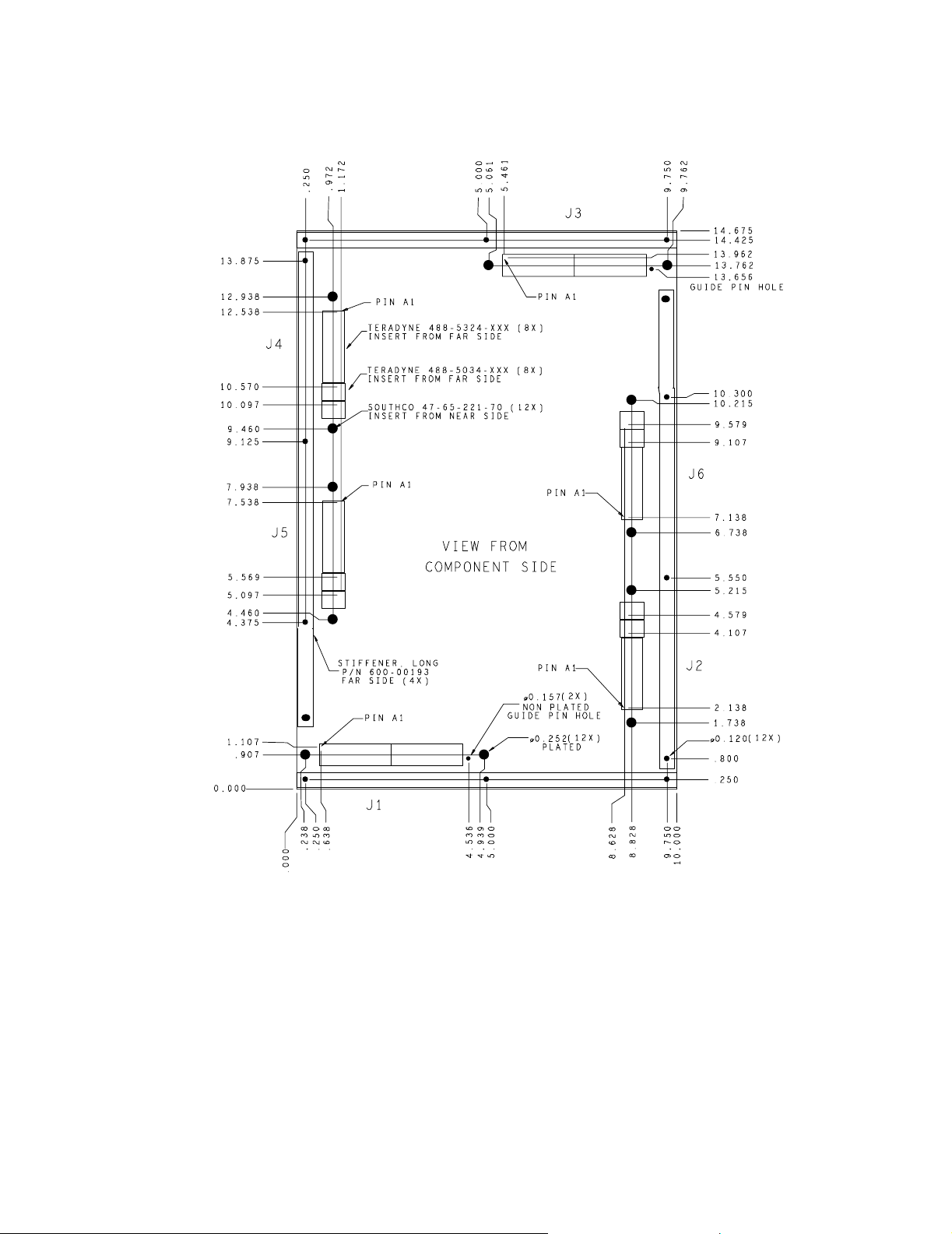
Figure 1 shows the physical specifications of the Daughterboard from the component
side. The Daughterboard is designed to have a footprint area in excess of 10” by 14”,
allowing for a multi-chip DUT.
Following are descriptions of some of the items shown on the drawing. All connectors
are to be installed from the far side.
● Guide pin holes: These are designed to mate with the guide pins on the Adapter to
ensure correct orientation when attaching the Daughterboard to the Adapter.
● Board stiffeners: Four (two long and two short) are required around the perimeter of
the Daughterboard to reinforce it. Fabrication drawings for compatible long and
short stiffeners are provided in Figure 3 on page 15.
● Connectors J1-J6: These are to be installed from the far side, and are designed to
mate with corresponding connectors on the Adapter. The location of Pin A1 of each
connector is indicated on the drawing. Details of the connector pins are provided in
text that follows.
November 2001 Synopsys, Inc. 11
Page 12
Chapter 2: Building the Daughterboard The ModelSource 640-pin Adapter
Figure 1: 640-pin Adapter Daughterboard
12 Synopsys, Inc. November 2001
Page 13

The ModelSource 640-pin Adapter Chapter 2: Building the Daughterboard
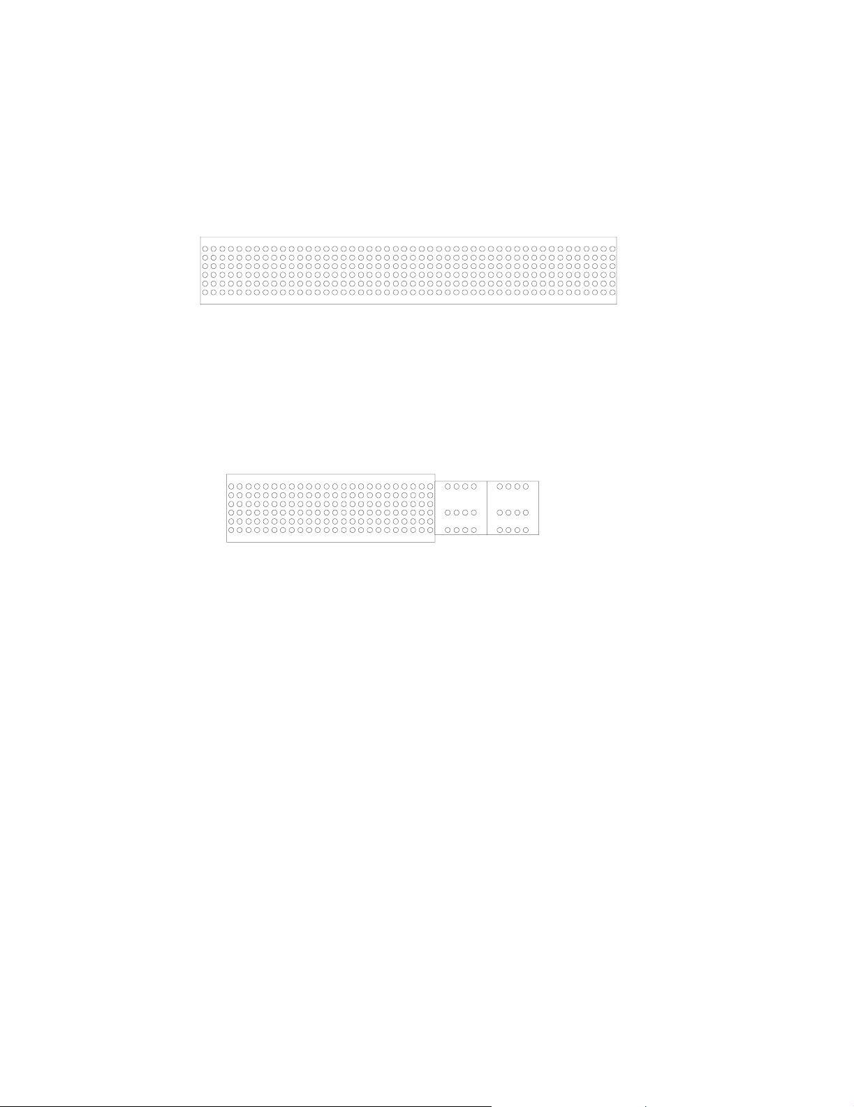
Connector Pin Detail
Connectors J1–J6 include the connections (DUT1–DUT640) between the DUT and the
Adapter through the Daughterboard and, in addition, supply voltage, ground
connections, and various auxiliary signals. Figure 2 shows details of J1–J6 connector
pins, from the component side. Pinouts are listed in “J1–J6 Connector Pinouts” on
page 29.
Connectors J1 and J3
These connectors include two each of Teradyne signal modules, and have 6 rows of 48
pins each. You will notice in Appendix A that no connections are listed for Rows B and
E; these are exclusively ground.
Connectors J2, J4, J5 and J6
These connectors include one each of Teradyne signal modules (A1–F24, at the left of
the figure) and two each of Teradyne power modules (AP1–FP4 and AP5–FP8, at the
right of the figure). As with connectors J1 and J3, the left (signal module) side has rows
B and E exclusively connected to ground. The right (power module) side has no rows B,
C, or E.
November 2001 Synopsys, Inc. 13
Page 14
Chapter 2: Building the Daughterboard The ModelSource 640-pin Adapter
Connectors J1 and J3
One Teradyne
Signal Module
1242448
A
B
C
D
E
F
Rows B and E are connected to ground
Connectors J2, J4, J5 and J6
One Teradyne
Signal Module
1
A
B
C
D
E
F
Rows B and E are
connected to ground do not exist
One Teradyne
Signal Module
Two Teradyne
Power Modules
AP1 AP8
DP1 DP8
FP1 FP8
Rows B, C, and E
Figure 2: Connector Pin Detail, Shown from Component Side
Parts List
The required parts are as follows:
● Eight Teradyne HDM signal modules, 488-5324-XXX. These are available either as
press fit or solder tail, in a variety of tail lengths. The last three digits (XXX) of the
part number depend on which type you choose; for specific part numbers, see the
Teradyne product documentation.
● Eight Teradyne HDM power modules, 437-5034-500. These are currently available
only as solder tail.
● Twelve Southco retractable screw fasteners, 47-65-221-70.
● To mount the stiffeners:
❍ Fourteen 4-40 1/4” pan head Phillips screws
14 Synopsys, Inc. November 2001
Page 15
The ModelSource 640-pin Adapter Chapter 2: Building the Daughterboard
❍ Fourteen #4 lock washers
❍ Fourteen #4 flat washers
● One EEProm, Catalyst semiconductor CAT93C86.
Note
The above does not include the package type designation; that is up to the
model designer.
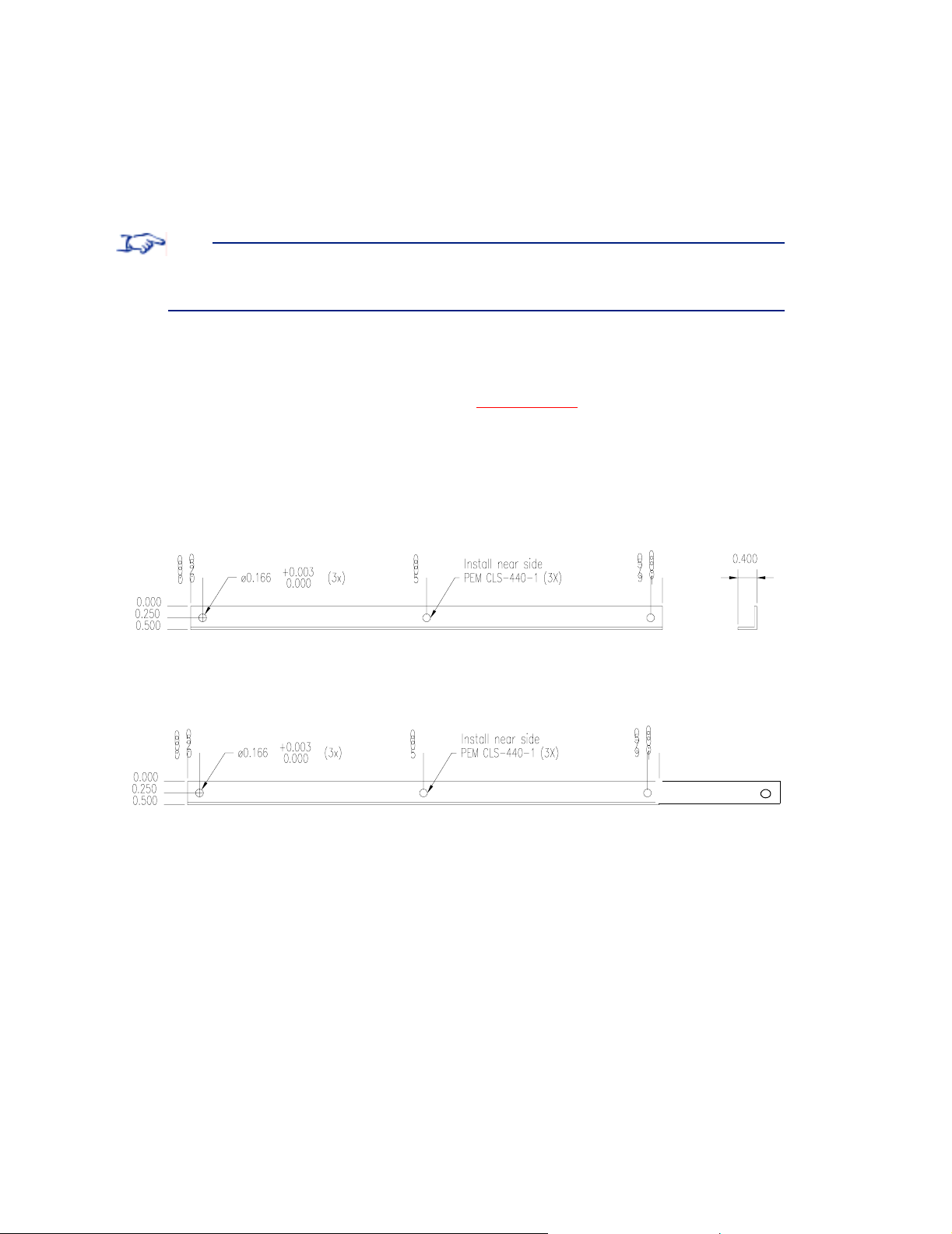
● Two Synopsys board stiffeners (short), 600-00193 (or build according to
specifications).
● Two Synopsys board stiffeners (long), 600-00XXX (or build according to
specifications).
Figure 3 shows a drawing of the short and long board stiffeners.
Short Stiffener
Long Stiffener
Figure 3: Fabrication Drawing of Board Stiffeners
Requirements
● You must locate the connectors and guide pin holes exactly as shown in Figure 1 on
page 12, so that the Daughterboard will fit onto the Adapter.
● The height of the DUT above the Daughterboard must not exceed 2.25 inches.
November 2001 Synopsys, Inc. 15
Page 16

Chapter 2: Building the Daughterboard The ModelSource 640-pin Adapter
● The DUT signal traces (DUT1 through DUT640) are controlled impedance, and
must be 93 ohms ± 10%. (All other signals are uncontrolled but will function
correctly at 93 ohms.)
● You must make the following specific connections:
❍ J1-A1 to J1-F48 (SEAT1)
❍ J2-A1 to J2-F24 (SEAT2)
❍ J3-A1 to J3-F48 (SEAT3)
❍ J4-A1 to J4-F24 (SEAT4)
❍ J5-A1 to J5-F24 (SEAT5)
❍ J6-A1 to J6-F24 (SEAT6)
(These connections pass a daisychain signal through all four J connectors to allow
the ModelSource system to detect whether or not the Adapter is seated correctly.)
● You must provide a series termination of 4.7 ohms within 1 inch of the DUT’s signal
pins. Use as small a surface mount package as can practically be mounted.
Routing Guidelines
Provide connections for your DUT device(s) on the Daughterboard. Route the DUT
signals (DUT1 through DUT640) and other appropriate signals to the J connector pins
according to the pinout listing in “J1–J6 Connector Pinouts” on page 29.
The following are some guidelines:
● For optimal pattern clock rates, ensure that all DUT signals are the same length, or
nearly so (within 0.5 inch).
● Use either microstrip (preferred) or stripline for the signal layers, but do not mix
them, because their propagation velocities are different. Use microstrip if the signal
routing fits on two layers; use stripline if the signal routing requires more than two
layers.
● For ease of testing, create test points for the following signals:
❍ J1-D17 (KEEPALIVE)
❍ J1-A15 (TRIGGER)
❍ J1-A19 (PLAY)
❍ J1-A17 (SAMPLE)
❍ Any voltages used by the DUT
16 Synopsys, Inc. November 2001
Page 17

The ModelSource 640-pin Adapter Chapter 2: Building the Daughterboard
❍ J4-FP5–J4-FP8 (FANP12V), if used
❍ DUT signal used for DUT clock
● You can connect to any of the available power supplies listed in Table 1. Do not
interconnect different power supplies.
Table 1: Available Power Supplies
Pins Signal Power Supply
J2-AP5–J2-AP8
P5V +5V DC, 6A max
J4-AP5–J4-AP8
J2-AP1–J2-AP4 ADJVCC1 +3-5V DC, 6A max
J4-AP1–J4-AP4 ADJVCC2 +3-5V DC, 6A max
J4-FP1–J4-FP4 M5V -5.2V DC, 400mA max
J2-FP5–J2-FP8 P12V +12V DC, 400mA max
J4-FP5–J4-FP8 FANP12V +12V DC, 400mA max (for
fan/heat sink only)
● For bypass/decoupling capacitors, follow the DUT manufacturer’s
recommendations, if provided; otherwise, use the following guidelines:
❍ For each supply of P5V, ADJVCC1 or ADJVCC2, provide 47µF, 16V tantalum
(use two of these, if space permits).
❍ For each supply of P12V, M5V, provide 10µF, 16V tantalum.
❍ For bypass, for every 25 signal pins, place a pair of 0.1µF and 0.01µF high
frequency X7R or NPO capacitors directly underneath the device, if possible, or
around the perimeter of the device.
November 2001 Synopsys, Inc. 17
Page 18

Chapter 2: Building the Daughterboard The ModelSource 640-pin Adapter
18 Synopsys, Inc. November 2001
Page 19

The ModelSource 640-pin Adapter Chapter 3: Connecting the Daughterboard
3
Connecting the Daughterboard
This section describes the Adapter and gives instructions for interconnecting it and the
Daughterboard.
Adapter Description
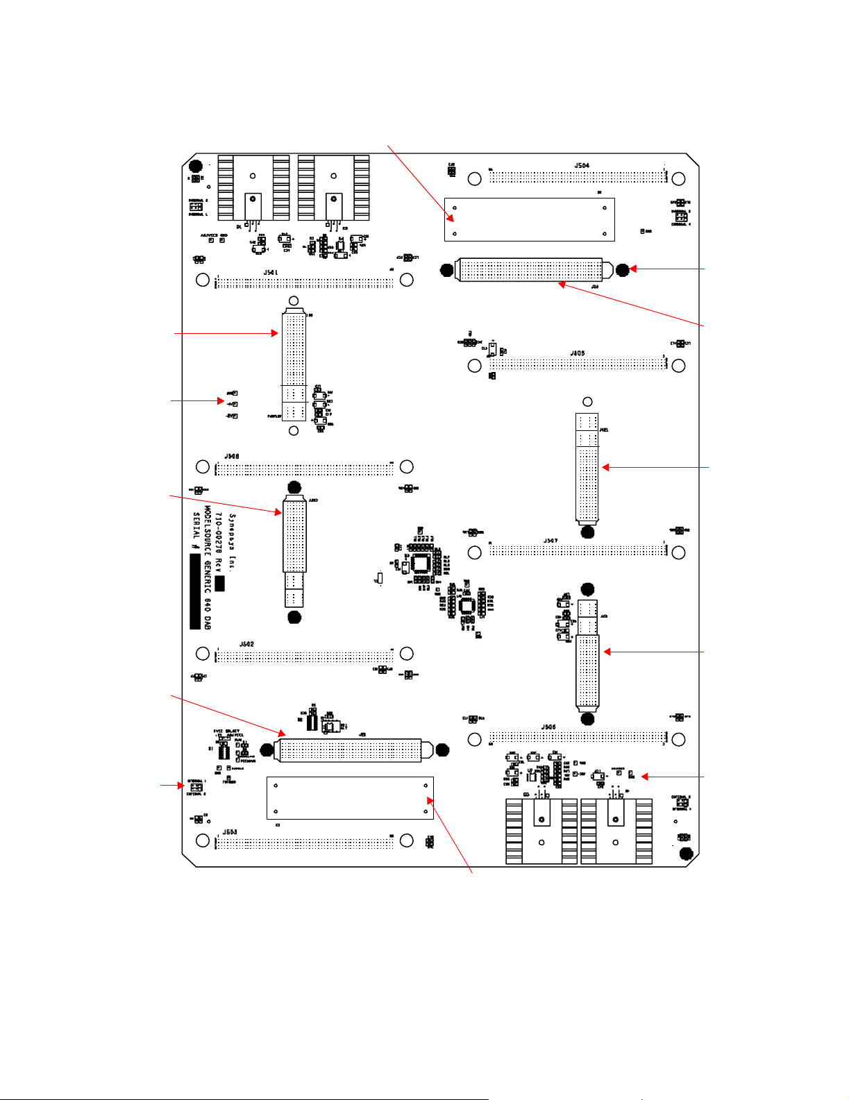
Figure 4 shows a drawing of the Adapter. The items of interest to the user are as follows:
● Connectors that mate with Daughterboard connectors J1–J6
● Ejectors for disconnecting the Daughterboard from the Adapter
● Guide pins that fit the Daughterboard guide pin holes to ensure correct orientation
● Test points for the signals TRIGGER, KEEPALIVE, PLAY, FEEDBACK,
SAMPLE, ADJVCC1, +5V, -5V, and GND
November 2001 Synopsys, Inc. 19
Page 20
Chapter 3: Connecting the Daughterboard The ModelSource 640-pin Adapter
2
6
3
Ejector
Guide
Pin
Mates
with J4
Test
Points
Mates
with J5
Mates
with J1
Mates
with J
Mates
with J
Mates
with J
Test
Points
Ejector
Test
Points
Figure 4: The 640-pin Generic Device Adapter
20 Synopsys, Inc. November 2001
Page 21

The ModelSource 640-pin Adapter Chapter 3: Connecting the Daughterboard
Procedures
Caution
Do not connect or disconnect the Daughterboard to or from the Adapter
while the Adapter is mounted on the ModelSource modeling systems.
To connect the Daughterboard to the Adapter, follow these steps:
1. Remove the lid from the Adapter.
2. Set the Daughterboard on the Adapter, engaging the guide pins through the guide
pin holes.
3. Push firmly to seat.
4. Hand-tighten each of the Southco retractable screw fasteners.
5. Replace the Adapter lid.
To disconnect the Daughterboard from the Adapter, follow these steps:
1. Remove the lid from the Adapter.
2. Loosen the Southco retractable screw fasteners.
3. Push the ejectors on the Adapter.
4. Carefully lift the Daughterboard from the Adapter.
5. Replace the Adapter lid.
November 2001 Synopsys, Inc. 21
Page 22

Chapter 3: Connecting the Daughterboard The ModelSource 640-pin Adapter
22 Synopsys, Inc. November 2001
Page 23

The ModelSource 640-pin Adapter Chapter 4: Developing the Shell Software
4
Developing the Shell Software
The Shell Software file requirements for a 640-pin Logic model are similar to those for
standard Logic Models, and are summarized here. For more information, see the Shell
Software Reference Manual.
User-Generated Files
As for all Generic Device Adapters, you must create one or more Shell Software files
that contain DUT-specific information, such as pinouts, device names, propagation
delays, timing checks.
Files Provided by Synopsys
● The Adapter Mapping (.ADP) file, GEN640.ADP: This file provides signal
mapping between the Adapter and the ModelSource modeling system. You should
be able to use this file without modification.
● A template Package Mapping (.PKG) file, GEN640.PKG: The .PKG file provides
signal mapping between the Daughterboard and the DUT; the template file contains
Daughterboard pin names mapped to duplicate pin names, for those pins used for
DUT signals. You create the custom .PKG file by editing the template and replacing
the duplicate pin names with your DUT pin names.
November 2001 Synopsys, Inc. 23
Page 24

Chapter 4: Developing the Shell Software The ModelSource 640-pin Adapter
Figure 5 shows part of the template GEN640.PKG file provided by Synopsys.
{*******************************************************************}
{* Copyright (c) 2001by Synopsys, Incorporated *}
{*All rights reserved. *}
{*******************************************************************}
{* Logic Model PACKAGE map file for Generic 640 Device Adapter. *}
{*******************************************************************}
{ package_map_revision A *}
{*******************************************************************}
package_mapping
J1A2 = J1A2
J1A3 = J1A3
J1A4 = J1A4
J1A5 = J1A5
J1A6 = J1A6
J1A7 = J1A7
J1A8 = J1A8
J1A9 = J1A9
J1A10 = J1A10
J1A11 = J1A11
J1A12 = J1A12
J1A13 = J1A13
J1A21 = J1A21
J1A22 = J1A22
J1A23 = J1A23
J1A24 = J1A24
J1A25 = J1A25
Figure 5: Partial GEN640.PKG File
T o customize this file for your DUT, you replace the first name on each line with the
name of the appropriate signal on your DUT.
For example, you change the first line
J1A2 = J1A2
to
DUTpname = J1A2
24 Synopsys, Inc. November 2001
Page 25

The ModelSource 640-pin Adapter Chapter 5: Completing the Model
5
Completing the Model
This chapter describes the tasks needed to complete the model: mounting the Adapter
onto the Modeling Systems, labeling the Daughterboard, and verifying the model. It also
describes how to unmount the Adapter from the Modeling Systems.
Mounting the Adapter onto the ModelSource Modeling Systems
To mount the Adapter onto the ModelSource modeling systems, follow these steps:
1. Make a stack of four MS3200 or four MS3400 modeling systems (do not mix these
two modeling systems). Connect the modeling systems together as described in
“Chapter 2: Installation” in the ModelSource User’s Manual.
Note
Do not stack the modelings systems more than four high. Ensure that the
surface on which the modelers are stacked is flat and rigid.
2. Place the base of the Adapter against the front of the sets of four connected
modeling systems, hanging the Adapter’ s hook receptacles on the positioning hooks
of the modeling systems. Pull the Adapter gently towards you to make sure that it is
securely balanced on the hooks.
3. Seat the modeling boards in the ModelSource modeling systems onto the Adapter as
described in the following paragraph.
Each modeling system has a knob on the right and on the left side for moving the
top and bottom modeling boards, respectively, backwards and forwards. Turn each
knob individually counterclockwise to bring each modeling board forward to
connect with the Adapter.
November 2001 Synopsys, Inc. 25
Page 26

Chapter 5: Completing the Model The ModelSource 640-pin Adapter
Labeling the Daughterboard
After you have completed the Shell Software and mounted the Adapter and
Daughterboard onto the ModelSource modeling systems, you must verify the
Daughterboard’s label and update it if necessary.
Note
Ensure that the Daughterboard is seated on the Adapter before you verify
and update the label. If the daughterboard is not seated, the software will
report the label as “GEN640”, the label of the Adapter itself.
If it is necessary to update the Daughterboard’s label, use the lm Label Device Adapter
utility to change the adapter’s label to the device_name used in the model’s Shell
Software. For more details, refer to “Label Device Adapter“ in the ModelSource User’s
Manual.
Verifying the Model
After you have developed the model, you must verify it. For more information, see the
ModelSource User’s Manual and the Logic Model Development Manual.
Note
The pattern memory available for simulation is limited to the smallest
amount of available memory on any one of the eight modeling boards in the
four modelers.
26 Synopsys, Inc. November 2001
Page 27

The ModelSource 640-pin Adapter Chapter 5: Completing the Model
Unmounting the Adapter from the ModelSource Modeling Systems
To remove the Adapter from the ModelSource modeling systems, follow these steps:
1. Ensure that the Adapter is not currently in use (that is, the In Use LEDs are not
illuminated).
2. Turn each knob individually clockwise, to unseat each modeling board connector
from the Adapter.
3. Verify that the “Seated LED” on each modeling board is no longer illuminated.
4. Push the Adapter so that it is flush against the front panel of the modeling system
assembly, and slide it up as far as you can.
5. Pull the Adapter straight out and away from the modeling system assembly.
November 2001 Synopsys, Inc. 27
Page 28

Chapter 5: Completing the Model The ModelSource 640-pin Adapter
28 Synopsys, Inc. November 2001
Page 29

The ModelSource 640-pin Adapter Appendix A: J1–J6 Connector Pinouts
A
J1–J6 Connector Pinouts
The pinouts for connectors J1 through J6 of the 640-pin Adapter and the Daughterboard
are listed in Table 2. Do not use pins that are labeled RESERVED.
Table 2: Pinouts for Connectors J1-J6
Connector Pin Signal
J1 A1 SEAT1
J1 A2 DUT171
J1 A3 DUT173
J1 A4 DUT170
J1 A5 DUT169
J1 A6 DUT168
J1 A7 DUT167
J1 A8 DUT166
J1 A9 DUT165
J1 A10 DUT164
J1 A11 DUT163
J1 A12 DUT162
J1 A13 DUT161
J1 A14 NC
J1 A15 TRIGGER
November 2001 Synopsys, Inc. 29
Page 30

Appendix A: J1–J6 Connector Pinouts The ModelSource 640-pin Adapter
Table 2: Pinouts for Connectors J1-J6
Connector Pin Signal
J1 A16 NC
J1 A17 SAMPLE
J1 A18 NC
J1 A19 PLAY
J1 A20 NC
J1 A21 DUT198
J1 A22 DUT197
J1 A23 DUT196
J1 A24 DUT202
J1 A25 DUT194
J1 A26 DUT193
J1 A27 DUT192
J1 A28 DUT191
J1 A29 DUT190
J1 A30 DUT189
J1 A31 DUT188
J1 A32 DUT187
J1 A33 DUT186
J1 A34 DUT185
J1 A35 DUT226
J1 A36 DUT225
J1 A37 DUT224
J1 A38 DUT223
J1 A39 DUT222
J1 A40 DUT221
30 Synopsys, Inc. November 2001
Page 31

The ModelSource 640-pin Adapter Appendix A: J1–J6 Connector Pinouts
Table 2: Pinouts for Connectors J1-J6
Connector Pin Signal
J1 A41 DUT220
J1 A42 DUT219
J1 A43 DUT218
J1 A44 DUT217
J1 A45 DUT237
J1 A46 DUT215
J1 A47 DUT214
J1 A48 DUT213
J1 C1 NC
J1 C2 DUT172
J1 C3 DUT174
J1 C4 DUT175
J1 C5 DUT176
J1 C6 DUT177
J1 C7 DUT178
J1 C8 DUT179
J1 C9 DUT180
J1 C10 DUT181
J1 C11 DUT182
J1 C12 DUT183
J1 C13 DUT184
J1 C14 NC
J1 C15 NC
J1 C16 NC
J1 C17 TEMP
November 2001 Synopsys, Inc. 31
Page 32

Appendix A: J1–J6 Connector Pinouts The ModelSource 640-pin Adapter
Table 2: Pinouts for Connectors J1-J6
Connector Pin Signal
J1 C18 NC
J1 C19 NC
J1 C20 NC
J1 C21 DUT199
J1 C22 DUT200
J1 C23 DUT201
J1 C24 DUT195
J1 C25 DUT203
J1 C26 DUT204
J1 C27 DUT205
J1 C28 DUT206
J1 C29 DUT207
J1 C30 DUT208
J1 C31 DUT209
J1 C32 DUT210
J1 C33 DUT211
J1 C34 DUT212
J1 C35 DUT227
J1 C36 DUT228
J1 C37 DUT229
J1 C38 DUT230
J1 C39 DUT231
J1 C40 DUT232
J1 C41 DUT233
J1 C42 DUT234
32 Synopsys, Inc. November 2001
Page 33

The ModelSource 640-pin Adapter Appendix A: J1–J6 Connector Pinouts
Table 2: Pinouts for Connectors J1-J6
Connector Pin Signal
J1 C43 DUT235
J1 C44 DUT236
J1 C45 DUT216
J1 C46 DUT238
J1 C47 DUT239
J1 C48 DUT240
J1 D1 DUT11
J1 D2 DUT13
J1 D3 DUT10
J1 D4 DUT9
J1 D5 DUT8
J1 D6 DUT7
J1 D7 DUT6
J1 D8 DUT5
J1 D9 DUT4
J1 D10 DUT3
J1 D11 DUT2
J1 D12 DUT1
J1 D13 NC
J1 D14 NC
J1 D15 FEEDBACK
J1 D16 NC
J1 D17 KEEPALIVE
J1 D18 NC
J1 D19 NC
November 2001 Synopsys, Inc. 33
Page 34

Appendix A: J1–J6 Connector Pinouts The ModelSource 640-pin Adapter
Table 2: Pinouts for Connectors J1-J6
Connector Pin Signal
J1 D20 DUT38
J1 D21 DUT37
J1 D22 DUT36
J1 D23 DUT42
J1 D24 DUT34
J1 D25 DUT33
J1 D26 DUT32
J1 D27 DUT31
J1 D28 DUT30
J1 D29 DUT29
J1 D30 DUT28
J1 D31 DUT27
J1 D32 DUT26
J1 D33 DUT25
J1 D34 DUT66
J1 D35 DUT65
J1 D36 DUT64
J1 D37 DUT63
J1 D38 DUT62
J1 D39 DUT61
J1 D40 DUT60
J1 D41 DUT59
J1 D42 DUT58
J1 D43 DUT57
J1 D44 DUT77
34 Synopsys, Inc. November 2001
Page 35

The ModelSource 640-pin Adapter Appendix A: J1–J6 Connector Pinouts
Table 2: Pinouts for Connectors J1-J6
Connector Pin Signal
J1 D45 DUT55
J1 D46 DUT54
J1 D47 DUT53
J1 D48 NC
J1 F1 DUT12
J1 F2 DUT14
J1 F3 DUT15
J1 F4 DUT16
J1 F5 DUT17
J1 F6 DUT18
J1 F7 DUT19
J1 F8 DUT20
J1 F9 DUT21
J1 F10 DUT22
J1 F11 DUT23
J1 F12 DUT24
J1 F13 NC
J1 F14 EEOUT
J1 F15 EEIN
J1 F16 EECLK
J1 F17 EEPE
J1 F18 EESEL
J1 F19 EEVCC
J1 F20 DUT39
J1 F21 DUT40
November 2001 Synopsys, Inc. 35
Page 36

Appendix A: J1–J6 Connector Pinouts The ModelSource 640-pin Adapter
Table 2: Pinouts for Connectors J1-J6
Connector Pin Signal
J1 F22 DUT41
J1 F23 DUT35
J1 F24 DUT43
J1 F25 DUT44
J1 F26 DUT45
J1 F27 DUT46
J1 F28 DUT47
J1 F29 DUT48
J1 F30 DUT49
J1 F31 DUT50
J1 F32 DUT51
J1 F33 DUT52
J1 F34 DUT67
J1 F35 DUT68
J1 F36 DUT69
J1 F37 DUT70
J1 F38 DUT71
J1 F39 DUT72
J1 F40 DUT73
J1 F41 DUT74
J1 F42 DUT75
J1 F43 DUT76
J1 F44 DUT56
J1 F45 DUT78
J1 F46 DUT79
36 Synopsys, Inc. November 2001
Page 37

The ModelSource 640-pin Adapter Appendix A: J1–J6 Connector Pinouts
Table 2: Pinouts for Connectors J1-J6
Connector Pin Signal
J1 F47 DUT80
J1 F48 SEAT1
J2 A1 SEAT2
J2 A2 DUT160
J2 A3 DUT159
J2 A4 DUT158
J2 A5 DUT136
J2 A6 DUT156
J2 A7 DUT155
J2 A8 DUT154
J2 A9 DUT153
J2 A10 DUT152
J2 A11 DUT151
J2 A12 DUT150
J2 A13 DUT149
J2 A14 DUT148
J2 A15 DUT147
J2 A16 DUT132
J2 A17 DUT131
J2 A18 DUT130
J2 A19 DUT129
J2 A20 DUT128
J2 A21 DUT127
J2 A22 NC
November 2001 Synopsys, Inc. 37
Page 38

Appendix A: J1–J6 Connector Pinouts The ModelSource 640-pin Adapter
Table 2: Pinouts for Connectors J1-J6
Connector Pin Signal
J2 A23 NC
J2 A24 NC
J2 C1 NC
J2 C2 DUT133
J2 C3 DUT134
J2 C4 DUT135
J2 C5 DUT157
J2 C6 DUT137
J2 C7 DUT138
J2 C8 DUT139
J2 C9 DUT140
J2 C10 DUT141
J2 C11 DUT142
J2 C12 DUT143
J2 C13 DUT144
J2 C14 DUT145
J2 C15 DUT146
J2 C16 DUT105
J2 C17 DUT106
J2 C18 DUT107
J2 C19 DUT108
J2 C20 DUT109
J2 C21 DUT110
J2 C22 NC
J2 C23 NC
38 Synopsys, Inc. November 2001
Page 39

The ModelSource 640-pin Adapter Appendix A: J1–J6 Connector Pinouts
Table 2: Pinouts for Connectors J1-J6
Connector Pin Signal
J2 C24 NC
J2 D1 NC
J2 D2 DUT91
J2 D3 DUT93
J2 D4 DUT90
J2 D5 DUT89
J2 D6 DUT88
J2 D7 DUT87
J2 D8 DUT86
J2 D9 DUT85
J2 D10 DUT84
J2 D11 DUT83
J2 D12 DUT82
J2 D13 DUT81
J2 D14 DUT118
J2 D15 DUT117
J2 D16 DUT116
J2 D17 DUT122
J2 D18 DUT114
J2 D19 DUT113
J2 D20 DUT112
J2 D21 DUT111
J2 D22 NC
J2 D23 NC
J2 D24 NC
November 2001 Synopsys, Inc. 39
Page 40

Appendix A: J1–J6 Connector Pinouts The ModelSource 640-pin Adapter
Table 2: Pinouts for Connectors J1-J6
Connector Pin Signal
J2 F1 NC
J2 F2 DUT92
J2 F3 DUT94
J2 F4 DUT95
J2 F5 DUT96
J2 F6 DUT97
J2 F7 DUT98
J2 F8 DUT99
J2 F9 DUT100
J2 F10 DUT101
J2 F11 DUT102
J2 F12 DUT103
J2 F13 DUT104
J2 F14 DUT119
J2 F15 DUT120
J2 F16 DUT121
J2 F17 DUT115
J2 F18 DUT123
J2 F19 DUT124
J2 F20 DUT125
J2 F21 DUT126
J2 F22 NC
J2 F23 NC
J2 F24 SEAT2
J2 AP1 ADJVCC1
40 Synopsys, Inc. November 2001
Page 41

The ModelSource 640-pin Adapter Appendix A: J1–J6 Connector Pinouts
Table 2: Pinouts for Connectors J1-J6
Connector Pin Signal
J2 AP2 ADJVCC1
J2 AP3 ADJVCC1
J2 AP4 ADJVCC1
J2 AP5 P5V
J2 AP6 P5V
J2 AP7 P5V
J2 AP8 P5V
J2 DP1 GND
J2 DP2 GND
J2 DP3 GND
J2 DP4 GND
J2 DP5 GND
J2 DP6 GND
J2 DP7 GND
J2 DP8 GND
J2 FP1 NC
J2 FP2 NC
J2 FP3 NC
J2 FP4 NC
J2 FP5 P12V
J2 FP6 P12V
J2 FP7 P12V
J2 FP8 P12V
J3 A1 SEAT3
November 2001 Synopsys, Inc. 41
Page 42

Appendix A: J1–J6 Connector Pinouts The ModelSource 640-pin Adapter
Table 2: Pinouts for Connectors J1-J6
Connector Pin Signal
J3 A2 DUT640
J3 A3 DUT639
J3 A4 DUT638
J3 A5 DUT616
J3 A6 DUT636
J3 A7 DUT635
J3 A8 DUT634
J3 A9 DUT633
J3 A10 DUT632
J3 A11 DUT631
J3 A12 DUT630
J3 A13 DUT629
J3 A14 DUT628
J3 A15 DUT627
J3 A16 DUT612
J3 A17 DUT611
J3 A18 DUT610
J3 A19 DUT609
J3 A20 DUT608
J3 A21 DUT607
J3 A22 DUT606
J3 A23 DUT605
J3 A24 DUT604
J3 A25 DUT603
J3 A26 DUT595
42 Synopsys, Inc. November 2001
Page 43

The ModelSource 640-pin Adapter Appendix A: J1–J6 Connector Pinouts
Table 2: Pinouts for Connectors J1-J6
Connector Pin Signal
J3 A27 DUT601
J3 A28 DUT600
J3 A29 DUT599
J3 A30 NC
J3 A31 RESERVED (AD13)
J3 A32 RESERVED (AD7)
J3 A33 RESERVED (AD5)
J3 A34 RESERVED (AD0)
J3 A35 RESERVED (-ACK)
J3 A36 NC
J3 A37 DUT584
J3 A38 DUT583
J3 A39 DUT582
J3 A40 DUT581
J3 A41 DUT580
J3 A42 DUT579
J3 A43 DUT578
J3 A44 DUT577
J3 A45 DUT576
J3 A46 DUT575
J3 A47 DUT574
J3 A48 DUT572
J3 C1 NC
J3 C2 DUT613
J3 C3 DUT614
November 2001 Synopsys, Inc. 43
Page 44

Appendix A: J1–J6 Connector Pinouts The ModelSource 640-pin Adapter
Table 2: Pinouts for Connectors J1-J6
Connector Pin Signal
J3 C4 DUT615
J3 C5 DUT637
J3 C6 DUT617
J3 C7 DUT618
J3 C8 DUT619
J3 C9 DUT620
J3 C10 DUT621
J3 C11 DUT622
J3 C12 DUT623
J3 C13 DUT624
J3 C14 DUT625
J3 C15 DUT626
J3 C16 DUT585
J3 C17 DUT586
J3 C18 DUT587
J3 C19 DUT588
J3 C20 DUT589
J3 C21 DUT590
J3 C22 DUT591
J3 C23 DUT592
J3 C24 DUT593
J3 C25 DUT594
J3 C26 DUT602
J3 C27 DUT596
J3 C28 DUT597
44 Synopsys, Inc. November 2001
Page 45

The ModelSource 640-pin Adapter Appendix A: J1–J6 Connector Pinouts
Table 2: Pinouts for Connectors J1-J6
Connector Pin Signal
J3 C29 DUT598
J3 C30 NC
J3 C31 RESERVED (AD11)
J3 C32 RESERVED (AD12)
J3 C33 RESERVED (AD6)
J3 C34 RESERVED (AD2)
J3 C35 RESERVED (-WR)
J3 C36 NC
J3 C37 DUT561
J3 C38 DUT562
J3 C39 DUT563
J3 C40 DUT564
J3 C41 DUT565
J3 C42 DUT566
J3 C43 DUT567
J3 C44 DUT568
J3 C45 DUT569
J3 C46 DUT570
J3 C47 DUT573
J3 C48 DUT571
J3 D1 DUT480
J3 D2 DUT479
J3 D3 DUT478
J3 D4 DUT456
J3 D5 DUT476
November 2001 Synopsys, Inc. 45
Page 46

Appendix A: J1–J6 Connector Pinouts The ModelSource 640-pin Adapter
Table 2: Pinouts for Connectors J1-J6
Connector Pin Signal
J3 D6 DUT475
J3 D7 DUT474
J3 D8 DUT473
J3 D9 DUT472
J3 D10 DUT471
J3 D11 DUT470
J3 D12 DUT469
J3 D13 DUT468
J3 D14 DUT467
J3 D15 DUT452
J3 D16 DUT451
J3 D17 DUT450
J3 D18 DUT449
J3 D19 DUT448
J3 D20 DUT447
J3 D21 DUT446
J3 D22 DUT445
J3 D23 DUT444
J3 D24 DUT443
J3 D25 DUT435
J3 D26 DUT441
J3 D27 DUT440
J3 D28 DUT439
J3 D29 NC
J3 D30 RESERVED (AD10)
46 Synopsys, Inc. November 2001
Page 47

The ModelSource 640-pin Adapter Appendix A: J1–J6 Connector Pinouts
Table 2: Pinouts for Connectors J1-J6
Connector Pin Signal
J3 D31 RESERVED (AD9)
J3 D32 RESERVED (AD3)
J3 D33 RESERVED (AD4)
J3 D34 RESERVED (-RD)
J3 D35 NC
J3 D36 DUT424
J3 D37 DUT423
J3 D38 DUT422
J3 D39 DUT421
J3 D40 DUT420
J3 D41 DUT419
J3 D42 DUT418
J3 D43 DUT417
J3 D44 DUT416
J3 D45 DUT415
J3 D46 DUT414
J3 D47 DUT412
J3 D48 NC
J3 F1 DUT453
J3 F2 DUT454
J3 F3 DUT455
J3 F4 DUT477
J3 F5 DUT457
J3 F6 DUT458
J3 F7 DUT459
November 2001 Synopsys, Inc. 47
Page 48

Appendix A: J1–J6 Connector Pinouts The ModelSource 640-pin Adapter
Table 2: Pinouts for Connectors J1-J6
Connector Pin Signal
J3 F8 DUT460
J3 F9 DUT461
J3 F10 DUT462
J3 F11 DUT463
J3 F12 DUT464
J3 F13 DUT465
J3 F14 DUT466
J3 F15 DUT425
J3 F16 DUT426
J3 F17 DUT427
J3 F18 DUT428
J3 F19 DUT429
J3 F20 DUT430
J3 F21 DUT431
J3 F22 DUT432
J3 F23 DUT433
J3 F24 DUT434
J3 F25 DUT442
J3 F26 DUT436
J3 F27 DUT437
J3 F28 DUT438
J3 F29 NC
J3 F30 RESERVED (AD14)
J3 F31 RESERVED (AD8)
J3 F32 RESERVED (AD1)
48 Synopsys, Inc. November 2001
Page 49

The ModelSource 640-pin Adapter Appendix A: J1–J6 Connector Pinouts
Table 2: Pinouts for Connectors J1-J6
Connector Pin Signal
J3 F33 RESERVED (AD15)
J3 F34 RESERVED (-AS)
J3 F35 NC
J3 F36 DUT401
J3 F37 DUT402
J3 F38 DUT403
J3 F39 DUT404
J3 F40 DUT405
J3 F41 DUT406
J3 F42 DUT407
J3 F43 DUT408
J3 F44 DUT409
J3 F45 DUT410
J3 F46 DUT413
J3 F47 DUT411
J3 F48 SEAT3
J4 A1 SEAT4
J4 A2 DUT560
J4 A3 DUT559
J4 A4 DUT558
J4 A5 DUT536
J4 A6 DUT556
J4 A7 DUT555
J4 A8 DUT554
November 2001 Synopsys, Inc. 49
Page 50

Appendix A: J1–J6 Connector Pinouts The ModelSource 640-pin Adapter
Table 2: Pinouts for Connectors J1-J6
Connector Pin Signal
J4 A9 DUT553
J4 A10 DUT552
J4 A11 DUT551
J4 A12 DUT550
J4 A13 DUT549
J4 A14 DUT548
J4 A15 DUT547
J4 A16 DUT532
J4 A17 DUT531
J4 A18 DUT530
J4 A19 DUT529
J4 A20 DUT528
J4 A21 DUT527
J4 A22 NC
J4 A23 NC
J4 A24 NC
J4 C1 NC
J4 C2 DUT533
J4 C3 DUT534
J4 C4 DUT535
J4 C5 DUT557
J4 C6 DUT537
J4 C7 DUT538
J4 C8 DUT539
J4 C9 DUT540
50 Synopsys, Inc. November 2001
Page 51

The ModelSource 640-pin Adapter Appendix A: J1–J6 Connector Pinouts
Table 2: Pinouts for Connectors J1-J6
Connector Pin Signal
J4 C10 DUT541
J4 C11 DUT542
J4 C12 DUT543
J4 C13 DUT544
J4 C14 DUT545
J4 C15 DUT546
J4 C16 DUT505
J4 C17 DUT506
J4 C18 DUT507
J4 C19 DUT508
J4 C20 DUT509
J4 C21 DUT510
J4 C22 NC
J4 C23 NC
J4 C24 NC
J4 D1 NC
J4 D2 DUT491
J4 D3 DUT493
J4 D4 DUT490
J4 D5 DUT489
J4 D6 DUT488
J4 D7 DUT487
J4 D8 DUT486
J4 D9 DUT485
J4 D10 DUT484
November 2001 Synopsys, Inc. 51
Page 52

Appendix A: J1–J6 Connector Pinouts The ModelSource 640-pin Adapter
Table 2: Pinouts for Connectors J1-J6
Connector Pin Signal
J4 D11 DUT483
J4 D12 DUT482
J4 D13 DUT481
J4 D14 DUT518
J4 D15 DUT517
J4 D16 DUT516
J4 D17 DUT522
J4 D18 DUT514
J4 D19 DUT513
J4 D20 DUT512
J4 D21 DUT511
J4 D22 NC
J4 D23 NC
J4 D24 NC
J4 F1 NC
J4 F2 DUT492
J4 F3 DUT494
J4 F4 DUT495
J4 F5 DUT496
J4 F6 DUT497
J4 F7 DUT498
J4 F8 DUT499
J4 F9 DUT500
J4 F10 DUT501
J4 F11 DUT502
52 Synopsys, Inc. November 2001
Page 53

The ModelSource 640-pin Adapter Appendix A: J1–J6 Connector Pinouts
Table 2: Pinouts for Connectors J1-J6
Connector Pin Signal
J4 F12 DUT503
J4 F13 DUT504
J4 F14 DUT519
J4 F15 DUT520
J4 F16 DUT521
J4 F17 DUT515
J4 F18 DUT523
J4 F19 DUT524
J4 F20 DUT525
J4 F21 DUT526
J4 F22 NC
J4 F23 NC
J4 F24 SEAT4
J4 AP1 ADJVCC2
J4 AP2 ADJVCC2
J4 AP3 ADJVCC2
J4 AP4 ADJVCC2
J4 AP5 P5V
J4 AP6 P5V
J4 AP7 P5V
J4 AP8 P5V
J4 DP1 GND
J4 DP2 GND
J4 DP3 GND
J4 DP4 GND
November 2001 Synopsys, Inc. 53
Page 54

Appendix A: J1–J6 Connector Pinouts The ModelSource 640-pin Adapter
Table 2: Pinouts for Connectors J1-J6
Connector Pin Signal
J4 DP5 GND
J4 DP6 GND
J4 DP7 GND
J4 DP8 GND
J4 FP1 M5V
J4 FP2 M5V
J4 FP3 M5V
J4 FP4 M5V
J4 FP5 FANP12V
J4 FP6 FANP12V
J4 FP7 FANP12V
J4 FP8 FANP12V
J5 A1 SEAT5
J5 A2 DUT400
J5 A3 DUT399
J5 A4 DUT398
J5 A5 DUT376
J5 A6 DUT396
J5 A7 DUT395
J5 A8 DUT394
J5 A9 DUT393
J5 A10 DUT392
J5 A11 DUT391
J5 A12 DUT390
54 Synopsys, Inc. November 2001
Page 55

The ModelSource 640-pin Adapter Appendix A: J1–J6 Connector Pinouts
Table 2: Pinouts for Connectors J1-J6
Connector Pin Signal
J5 A13 DUT389
J5 A14 DUT388
J5 A15 DUT387
J5 A16 DUT372
J5 A17 DUT371
J5 A18 DUT370
J5 A19 DUT369
J5 A20 DUT368
J5 A21 DUT367
J5 A22 NC
J5 A23 NC
J5 A24 NC
J5 C1 NC
J5 C2 DUT373
J5 C3 DUT374
J5 C4 DUT375
J5 C5 DUT397
J5 C6 DUT377
J5 C7 DUT378
J5 C8 DUT379
J5 C9 DUT380
J5 C10 DUT381
J5 C11 DUT382
J5 C12 DUT383
J5 C13 DUT384
November 2001 Synopsys, Inc. 55
Page 56

Appendix A: J1–J6 Connector Pinouts The ModelSource 640-pin Adapter
Table 2: Pinouts for Connectors J1-J6
Connector Pin Signal
J5 C14 DUT385
J5 C15 DUT386
J5 C16 DUT345
J5 C17 DUT346
J5 C18 DUT347
J5 C19 DUT348
J5 C20 DUT349
J5 C21 DUT350
J5 C22 NC
J5 C23 NC
J5 C24 NC
J5 D1 NC
J5 D2 DUT331
J5 D3 DUT333
J5 D4 DUT330
J5 D5 DUT329
J5 D6 DUT328
J5 D7 DUT327
J5 D8 DUT326
J5 D9 DUT325
J5 D10 DUT324
J5 D11 DUT323
J5 D12 DUT322
J5 D13 DUT321
J5 D14 DUT358
56 Synopsys, Inc. November 2001
Page 57

The ModelSource 640-pin Adapter Appendix A: J1–J6 Connector Pinouts
Table 2: Pinouts for Connectors J1-J6
Connector Pin Signal
J5 D15 DUT357
J5 D16 DUT356
J5 D17 DUT362
J5 D18 DUT354
J5 D19 DUT353
J5 D20 DUT352
J5 D21 DUT351
J5 D22 NC
J5 D23 NC
J5 D24 NC
J5 F1 NC
J5 F2 DUT332
J5 F3 DUT334
J5 F4 DUT335
J5 F5 DUT336
J5 F6 DUT337
J5 F7 DUT338
J5 F8 DUT339
J5 F9 DUT340
J5 F10 DUT341
J5 F11 DUT342
J5 F12 DUT343
J5 F13 DUT344
J5 F14 DUT359
J5 F15 DUT360
November 2001 Synopsys, Inc. 57
Page 58

Appendix A: J1–J6 Connector Pinouts The ModelSource 640-pin Adapter
Table 2: Pinouts for Connectors J1-J6
Connector Pin Signal
J5 F16 DUT361
J5 F17 DUT355
J5 F18 DUT363
J5 F19 DUT364
J5 F20 DUT365
J5 F21 DUT366
J5 F22 NC
J5 F23 NC
J5 F24 SEAT5
J5 AP1 RESERVED
J5 AP2 RESERVED
J5 AP3 RESERVED
J5 AP4 RESERVED
J5 AP5 RESERVED
J5 AP6 RESERVED
J5 AP7 RESERVED
J5 AP8 RESERVED
J5 DP1 GND
J5 DP2 GND
J5 DP3 GND
J5 DP4 GND
J5 DP5 GND
J5 DP6 GND
J5 DP7 GND
J5 DP8 GND
58 Synopsys, Inc. November 2001
Page 59

The ModelSource 640-pin Adapter Appendix A: J1–J6 Connector Pinouts
Table 2: Pinouts for Connectors J1-J6
Connector Pin Signal
J5 FP1 RESERVED
J5 FP2 RESERVED
J5 FP3 RESERVED
J5 FP4 RESERVED
J5 FP5 RESERVED
J5 FP6 RESERVED
J5 FP7 RESERVED
J5 FP8 RESERVED
J6 A1 SEAT6
J6 A2 DUT320
J6 A3 DUT319
J6 A4 DUT318
J6 A5 DUT296
J6 A6 DUT316
J6 A7 DUT315
J6 A8 DUT314
J6 A9 DUT313
J6 A10 DUT312
J6 A11 DUT311
J6 A12 DUT310
J6 A13 DUT309
J6 A14 DUT308
J6 A15 DUT307
J6 A16 DUT292
November 2001 Synopsys, Inc. 59
Page 60

Appendix A: J1–J6 Connector Pinouts The ModelSource 640-pin Adapter
Table 2: Pinouts for Connectors J1-J6
Connector Pin Signal
J6 A17 DUT291
J6 A18 DUT290
J6 A19 DUT289
J6 A20 DUT288
J6 A21 DUT287
J6 A22 NC
J6 A23 NC
J6 A24 NC
J6 C1 NC
J6 C2 DUT293
J6 C3 DUT294
J6 C4 DUT295
J6 C5 DUT317
J6 C6 DUT297
J6 C7 DUT298
J6 C8 DUT299
J6 C9 DUT300
J6 C10 DUT301
J6 C11 DUT302
J6 C12 DUT303
J6 C13 DUT304
J6 C14 DUT305
J6 C15 DUT306
J6 C16 DUT265
J6 C17 DUT266
60 Synopsys, Inc. November 2001
Page 61

The ModelSource 640-pin Adapter Appendix A: J1–J6 Connector Pinouts
Table 2: Pinouts for Connectors J1-J6
Connector Pin Signal
J6 C18 DUT267
J6 C19 DUT268
J6 C20 DUT269
J6 C21 DUT270
J6 C22 NC
J6 C23 NC
J6 C24 NC
J6 D1 NC
J6 D2 DUT251
J6 D3 DUT253
J6 D4 DUT250
J6 D5 DUT249
J6 D6 DUT248
J6 D7 DUT247
J6 D8 DUT246
J6 D9 DUT245
J6 D10 DUT244
J6 D11 DUT243
J6 D12 DUT242
J6 D13 DUT241
J6 D14 DUT278
J6 D15 DUT277
J6 D16 DUT276
J6 D17 DUT282
J6 D18 DUT274
November 2001 Synopsys, Inc. 61
Page 62

Appendix A: J1–J6 Connector Pinouts The ModelSource 640-pin Adapter
Table 2: Pinouts for Connectors J1-J6
Connector Pin Signal
J6 D19 DUT273
J6 D20 DUT272
J6 D21 DUT271
J6 D22 NC
J6 D23 NC
J6 D24 NC
J6 F1 NC
J6 F2 DUT252
J6 F3 DUT254
J6 F4 DUT255
J6 F5 DUT256
J6 F6 DUT257
J6 F7 DUT258
J6 F8 DUT259
J6 F9 DUT260
J6 F10 DUT261
J6 F11 DUT262
J6 F12 DUT263
J6 F13 DUT264
J6 F14 DUT279
J6 F15 DUT280
J6 F16 DUT281
J6 F17 DUT275
J6 F18 DUT283
J6 F19 DUT284
62 Synopsys, Inc. November 2001
Page 63

The ModelSource 640-pin Adapter Appendix A: J1–J6 Connector Pinouts
Table 2: Pinouts for Connectors J1-J6
Connector Pin Signal
J6 F20 DUT285
J6 F21 DUT286
J6 F22 NC
J6 F23 NC
J6 F24 SEAT6
J6 AP1 RESERVED
J6 AP2 RESERVED
J6 AP3 RESERVED
J6 AP4 RESERVED
J6 AP5 RESERVED
J6 AP6 RESERVED
J6 AP7 RESERVED
J6 AP8 RESERVED
J6 DP1 GND
J6 DP2 GND
J6 DP3 GND
J6 DP4 GND
J6 DP5 GND
J6 DP6 GND
J6 DP7 GND
J6 DP8 GND
J6 FP1 NC
J6 FP2 NC
J6 FP3 NC
J6 FP4 NC
November 2001 Synopsys, Inc. 63
Page 64

Appendix A: J1–J6 Connector Pinouts The ModelSource 640-pin Adapter
Table 2: Pinouts for Connectors J1-J6
Connector Pin Signal
J6 FP5 RESERVED
J6 FP6 RESERVED
J6 FP7 RESERVED
J6 FP8 RESERVED
64 Synopsys, Inc. November 2001
 Loading...