

Page 1
Expansion Unit DX517
Hardware Installation Guide
Page 2

Table of Contents
Chapter 1: Before You Start
Package Contents 3
Expansion Unit at a Glance 4
Safety Instructions 5
Chapter 2: Hardware Setup
Tools and Parts for Drive Installation 6
Install Drives 6
Connect with Synology DiskStation 9
Replace System Fan 9
Conrm Connection and Manage Storage Spaces 10
Learn More 11
Appedix A: Specications
Appedix B: LED Indicator Table
Synology_QIG_DX517_20161128
2
Page 3
Chapter
Before You Start
Thank you for purchasing this Synology product! Before setting up your new expansion unit, please check the
package contents to verify that you have received the items below. Also, make sure to read the safety instructions
carefully to avoid harming yourself or damaging your expansion unit.
Note:
All images below are for illustrative purposes only, and may differ from the actual product.
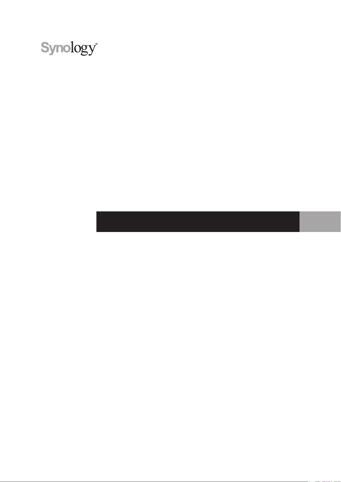
Package Contents
Main unit x 1 AC power cord x 1
Screws for 2.5” drives x 24
1
Expansion cable x 1 Drive tray key x 2
3
3
Page 4
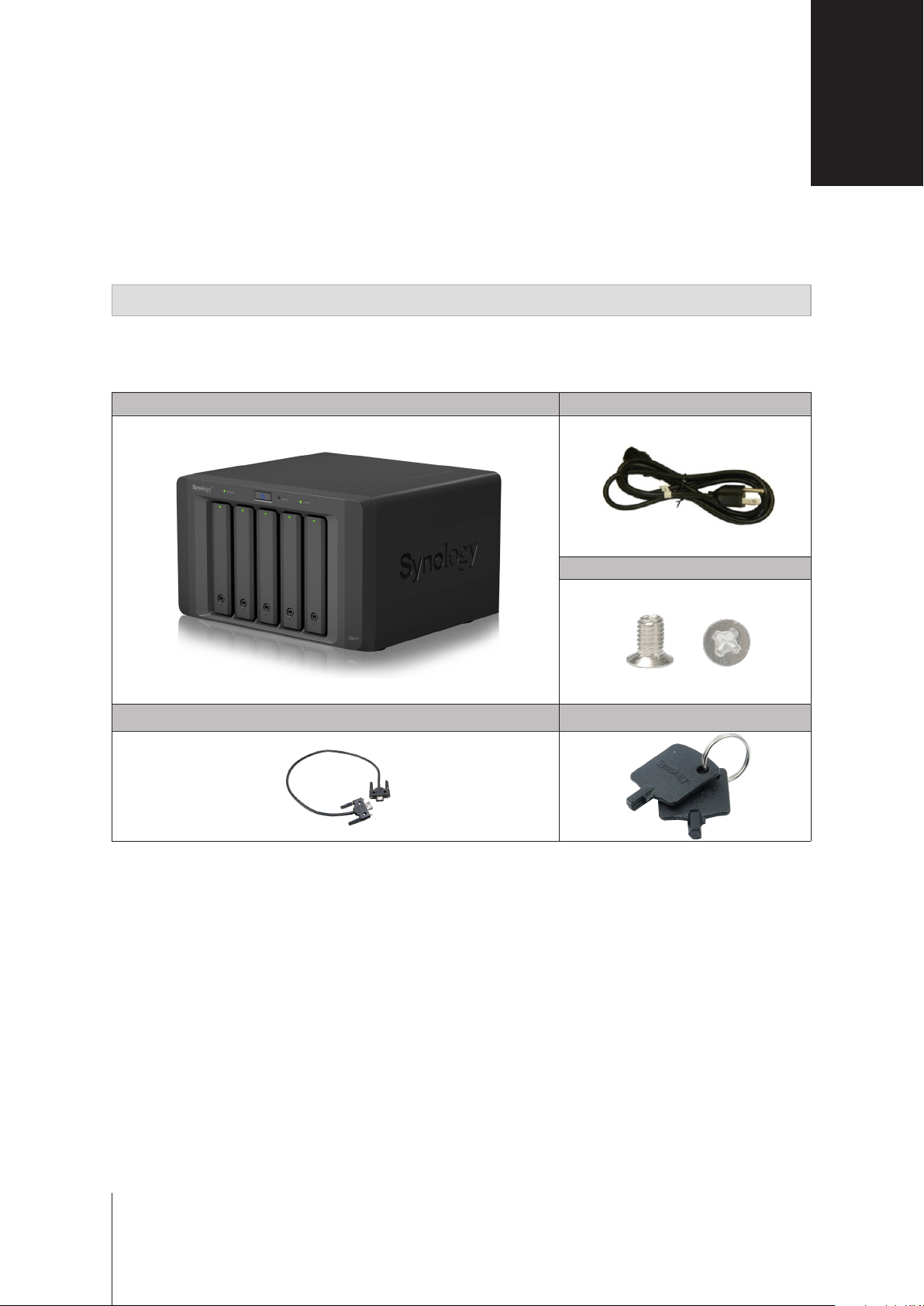
Expansion Unit at a Glance
No. Article Name Location Description
1
2
3
4
5
6
7
LED Indicator
Power Button
Drive Tray Lock Lock or unlock drive trays.
Drive Tray Install drives (hard disk drives or solid state drives) here.
Power Port
Expansion Port
Fan
4 Chapter 1: Before You Start
Front
Back
Displays the status of internal drives and the system. For more
information, please see
1. Press to power on the expansion unit.
2. Press and hold to shut down.
Note:
The expansion unit will be turned on or off automatically when the
linked DiskStation powers on or off. However, the POWER button has no
power-off function when volume is created to prevent accidental volume
damage.
Connect the AC power cord here.
Connect Synology DiskStation here. For the list of supported models,
please see the
Disposes of excess heat and cools the expansion unit. If the fan
malfunctions, the ALERT LED indicator will show a blinking red light.
Appedix A: Specications
Appedix B: LED Indicator Table.
.
Page 5

Safety Instructions
Keep away from direct sunlight and away from chemicals. Make sure the environment does not
experience abrupt changes in temperature or humidity.
Place the product right side up at all times.
Do not place near any liquids.
Before cleaning, unplug the power cord. Wipe with damp paper towels. Do not use chemical or
aerosol cleaners.
To prevent the unit from falling over, do not place on carts or any unstable surfaces.
The power cord must plug in to the correct supply voltage. Make sure that the supplied AC voltage is
correct and stable.
To remove all electrical current from the device, ensure that all power cords are disconnected from
the power source.
Risk of explosion if battery is replaced with an incorrect type. Dispose of used batteries appropriately.
5 Chapter 1: Before You Start
Page 6

Chapter
Hardware Setup
Tools and Parts for Drive Installation
• A screwdriver
• At least one 3.5” or 2.5” SATA drive (please visit
Warning:
back up any important data before installation.
If you install a drive that contains data, the system will format the drive and erase all existing data. Please
Install Drives
1
Press the lower part of the drive tray to pop out the handle.
www.synology.com
2
for compatible drive models.)
2
Pull the drive tray handle in the direction as indicated below to remove the drive tray.
6
Page 7

3
Load drives in the drive trays:
For 3.5” drives:
•
tray. Then insert the fastening panels to secure the drive in place.
For 2.5” drives:
•
place. Place the drive in the blue area (shown below) of the drive tray. Turn the tray upside down and tighten
the screws to secure the drive in place.
4
Insert the loaded drive tray into the empty drive bay.
Remove the fastening panels from the sides of the drive tray. Place the drive in the drive
Remove the fastening panels from the sides of the drive tray and store them in a safe
Note:
Make sure the tray is pushed in all the way. Otherwise, the drive might not be able to function properly.
7 Chapter 2: Hardware Setup
Page 8

5
Press the handle in ush with the front panel to hold the drive tray in place.
6
Insert the drive tray key into the drive tray lock, turn the key clockwise to lock the handle of the drive tray, and
then remove the key.
7
Repeat the steps above to assemble the other drives you have prepared.
8
Drives are numbered as shown below.
Note:
If you want to create a RAID volume, we recommend all installed drives be the same size in order to optimize
drive capacity usage.
8 Chapter 2: Hardware Setup
Page 9

Connect with Synology DiskStation
1
Connect one end of the power cord to the power port of the expansion unit, and the other to the power outlet.
2
Connect the expansion cable to the expansion ports of DX517 and Synology DiskStation:
After the connection is complete, DX517 will be turned on or off automatically when the connected DiskStation
powers on or off.
Replace System Fan
The ALERT LED indicator of your DX517 will be static orange if either of the system fans is not working. Follow
the steps below to replace the malfunctioning fan with a good one.
1
Shut down your expansion unit. Disconnect all cables connected to your expansion unit to prevent any
possible damages.
2
Fans are numbered as follows:
9 Chapter 2: Hardware Setup
Page 10

3
Remove the screws that secure the fan panels and pull the panels from the expansion unit.
4
Remove the malfunctioning fans by disconnecting the fan cable from the connectors.
5
Connect the cables of the new fans to the connectors and tighten the screws removed in step 3.
Conrm Connection and Manage Storage Spaces
1
Log in to the DiskStation Manager (DSM) of the main DiskStation unit.
2
Control Panel
Go to
connected.
External Devices
>
External Devices
>
to conrm the expansion unit is successfully
10 Chapter 2: Hardware Setup
Page 11

3
Storage Manager
Go to
If you want to create a new volume on the expansion
•
wizard.
If you want to expand an existing volume with expansion unit
•
from the volume list, click
to manage storage space creation or expansion.
Manage
, and follow the instructions of the wizard
, click
Create
and follow the instructions of the
, select the volume you want to expand
.
For detailed information about volume management, go to
Limitations:
• This expansion unit can be linked to only one Synology DiskStation at a time.
• The data of some DSM packages can be stored on the expansion unit only if you create an expanded volume with it.
The data cannot be stored on the expansion unit if an independent volume has been created on it.
• Drives previously used in a Synology DiskStation are not readable when directly inserting them into this expansion unit,
and vise versa.
Before using this expansion unit, please see the limitations below.
Storage Manager
and see
DSM Help
Learn More
Congratulations! Your expansion unit is now ready for action. For more information or online resources about
your DiskStation, please visit
11 Chapter 2: Hardware Setup
www.synology.com
.
.
Page 12

Appendix
Specications
Item DX517
Compatible Drive Type 3.5" / 2.5" SATA x 5
Expansion Port # 1
Maximum Internal Raw Capacity 50TB (5 x 10TB HDD)
Hot Swappable Drive Yes
Size (HxWxD) (mm) 157 x 248 x 233
Weight (kg) 3.91
AC Input Power Voltage 100V to 240V AC
Power Frequency 50/60Hz, Single Phase
Operating Temperature 5°C to 40°C (40°F to 104°F)
Storage Temperature -10°C to 70°C (15°F to 155°F)
Relative Humidity 5% to 95% RH
Certication FCC Class B • CE Class B • BSMI Class B
Supported Models DS1517+, DS1817+
A
Note:
Please visit
www.synology.com
for the latest compatible models.
12
Page 13

Appendix
LED Indicator Table
LED Indicator Color Status Description
ALERT
eS ATA
Drive status
(on trays)
POWER
STATUS
Note:
Model specications are subject to change without notice. Please refer to
Orange Static System fan malfunctioning
Off System fan normal
Green Static Connected to Synology DiskStation
Off Not connected to Synology DiskStation
Green
Orange Static Drive error
Off No internal drive
Blue Static Powered on
Off Powered off
Green
Orange Volume degraded / Volume crashed
Off No volume
Static Drive ready and idle
Blinking Accessing drive
Static
www.synology.com
Volume normal / HDD hibernation
for the latest information.
B
13
 Loading...