

SynerTech 1 family, 2 family Installation And Operation Manual

Wireless Audio Doorphone
Installation and operation manual
(Model: For 1 family & 2 family)
1.Introduction
Thank you for purchasing this SynerTech product.
Wireless ADP is ideal for your home. Features included: communication, 1 or 2 household call buttons,
and Single door/Garage door release. The operating frequency is at 2.4G Hz.
Full set of wireless audio door phone system includes 1 door station and 1 indoor unit with charger.
Accessories include one wall mounting bracket and screws.
The door station has 1 or 2 household call buttons. When pressed, it allows 2 way speech
communications and will ring only one indoor wireless handset corresponding to that call button. The
wireless handset can be carried from floor to floor.
To obtain the best performance from this product, please read through this manual carefully.
P. 1 of 14
2.Components
A. Name of parts, accessories and indicators for full set of wireless ADP
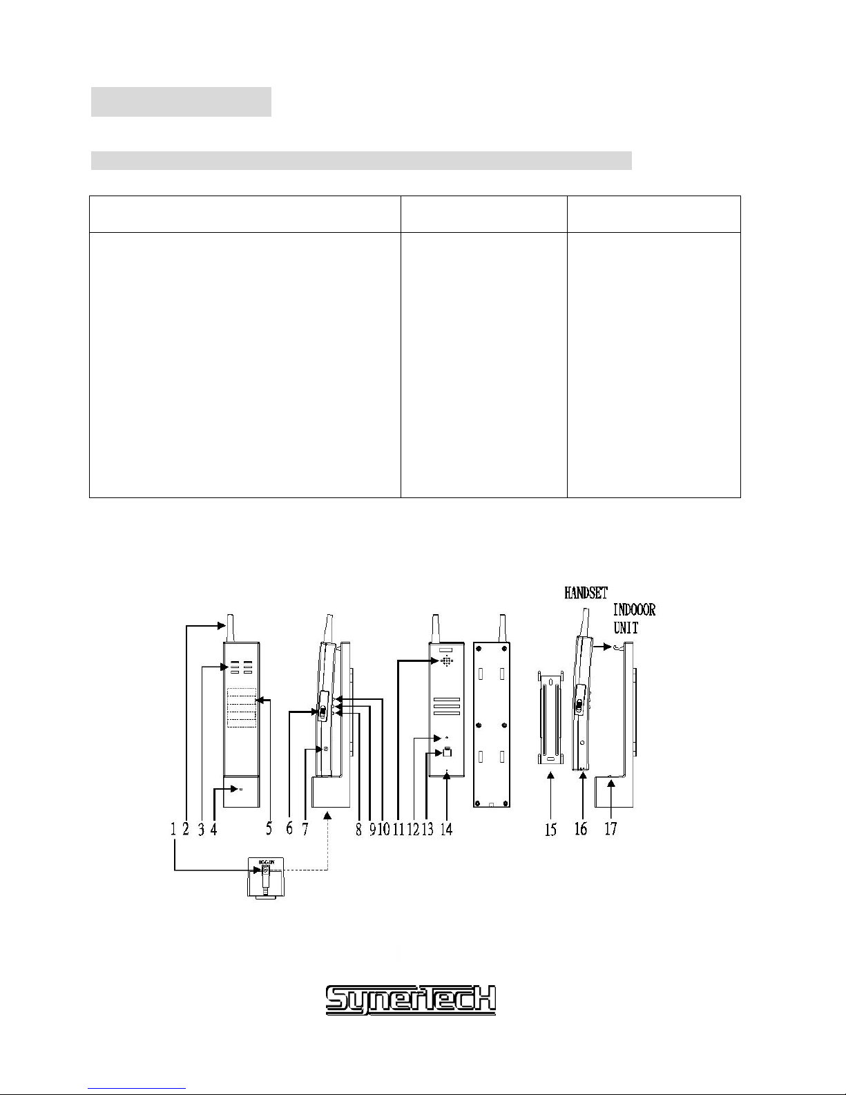
Handset (Fig.1) Indoor unit Accessories
(Included)
1. DC jack
2. Antenna
3. Built-in speaker
4. LED light
5. Rechargeable Battery
6. Battery door
7. Volume control knob for 8 chorus sound
8. “GARAGE OPENER ” button
9. “DOOR OPENER ” button
10. “TALK ” button
11. Built-in speaker
12. LED indicator
13. DIP switches
14. Built-in microphone
16. Charging contact
15. Metal wall mounting
bracket
17. Charging
contact
I. Screws
Handset and indoor unit
Fig. 1
P. 2 of 14
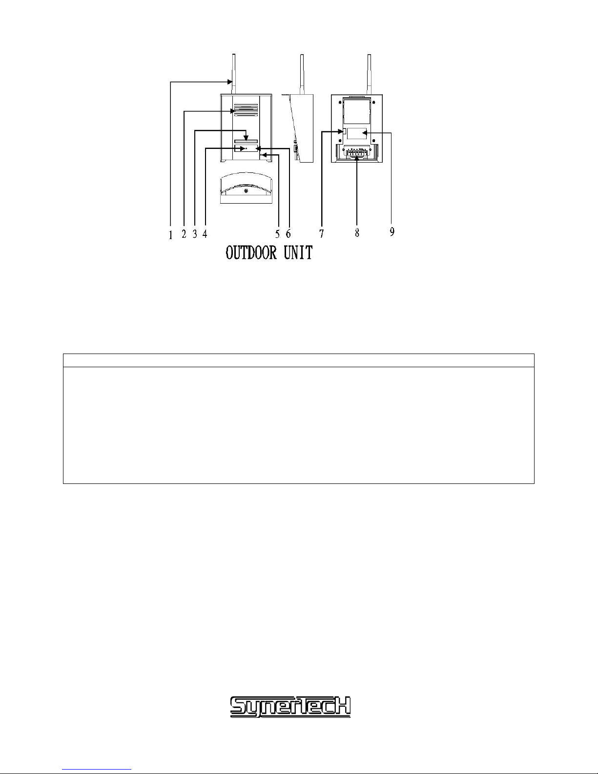
Fig. 2
Door station(Fig.2)
1. Antenna
2. Built-in speaker
3. Door Button
4. LED 1: low battery indicator / coding setting indicator
5. Microphone
6. Name plate (two LEDs ( LED 2 & 3 ) under name plate )
7. DIP switches
8. Terminals
9. Sticker
P. 3 of 14

3.Setting of Wireless System
1) Put the relevant batteries inside the handset & door station
2) Battery pack for handset is provided. Simply plug the battery pack inside the socket near the battery
door. ( See fig.7-2 )
You could select one out of 3 available channels to use.
Make sure the channel between door station and handset is the same.
Handset
Dip switch Channel selection
1. 2-ON 3-ON Channel 1
2. 2-ON 3-OFF Channel 2
3. 2-OFF 3-ON Channel 3
Door station
Dip Switch Channel selection
1. 2-ON 3-ON Channel 1
2. 2-ON 3-OFF Channel 2
3. 2-OFF 3-ON Channel 3
4. should be in “ Off “ position in normal condition
5. should be in “ Off “ position in normal condition
For example, the user choose channel 1 for setting:
The setting procedure is as below:
3) Put the DIP switch 1 to “ ON “ position from the handset.
4) Put the DIP switch 4 to “ ON “ position from the door station. ( For program setting
purpose )
5) Press the call button from the door station.
6) If the identification is done, the LED on the door station would be red & green blinking.
7) Put the DIP switch 4 to “ OFF “ position from the door station
8) Put the DIP switch 1 to “ OFF “ position from the handset
9) Press the call button from the door station to ensure the product is in function.
For setting wireless audio door phone for family two, the procedure is same as
above except the user needs to press the appropriate call button from the door
station during identification.
P. 4 of 14

Select the other channel if any disturbance occurred.
LED indicator from handset: (see fig. 1)
a) When the low battery status from door station, the LED would blink in red & green.
b) When the low battery status from handset, the LED would be on in red.
c) The LED would be in green when battery is charged up.
LED indicator from the door station (see fig.2: point 4)
z Low battery indicator: green light indicates the batteries are in operating level, red light
indicates low battery. Red light would only turn back to green after changing of new
batteries .
z Press the call button from the door station once to activate the setting again after change
of batteries.
z If the LED turns red & green blinking, it means the successful of code setting between
handset and door station.
Installation Precaution:
Please change to use another frequency if the conversation or images suffer interference from
the surroundings.
When in test model, there will be no door open function
Quality of the images and sound for wireless system will vary according to environmental
conditions, which will also affect the transmission and receiving range. For the best quality,
these functions should be tested before actual installation.
To obtain the best signal transmission, install the indoor unit and door station vertically
on the wall and they should be on the same height from the ground. ( See Fig.6 )
If the signal transmission is weak when using “ table top “ for the indoor unit, install the
indoor unit on the wall vertically to obtain better performance.
P. 5 of 14
 Loading...