

Page 1
w w w .s y n e r g yr c h e lic o p t e r s .c o m
Page 2
w w w .s y n e r g y r c h e lic o p t e r s .c o m
Page 3
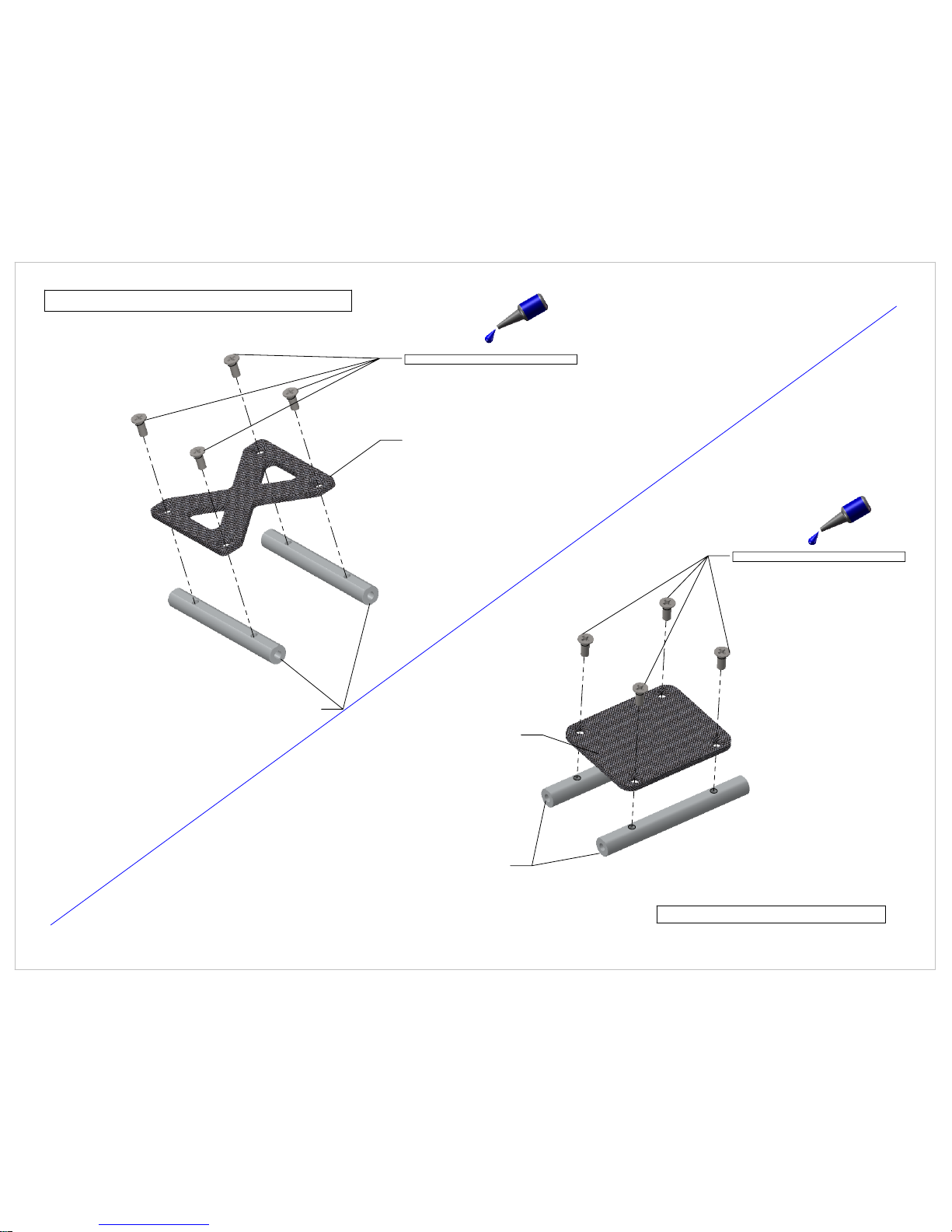
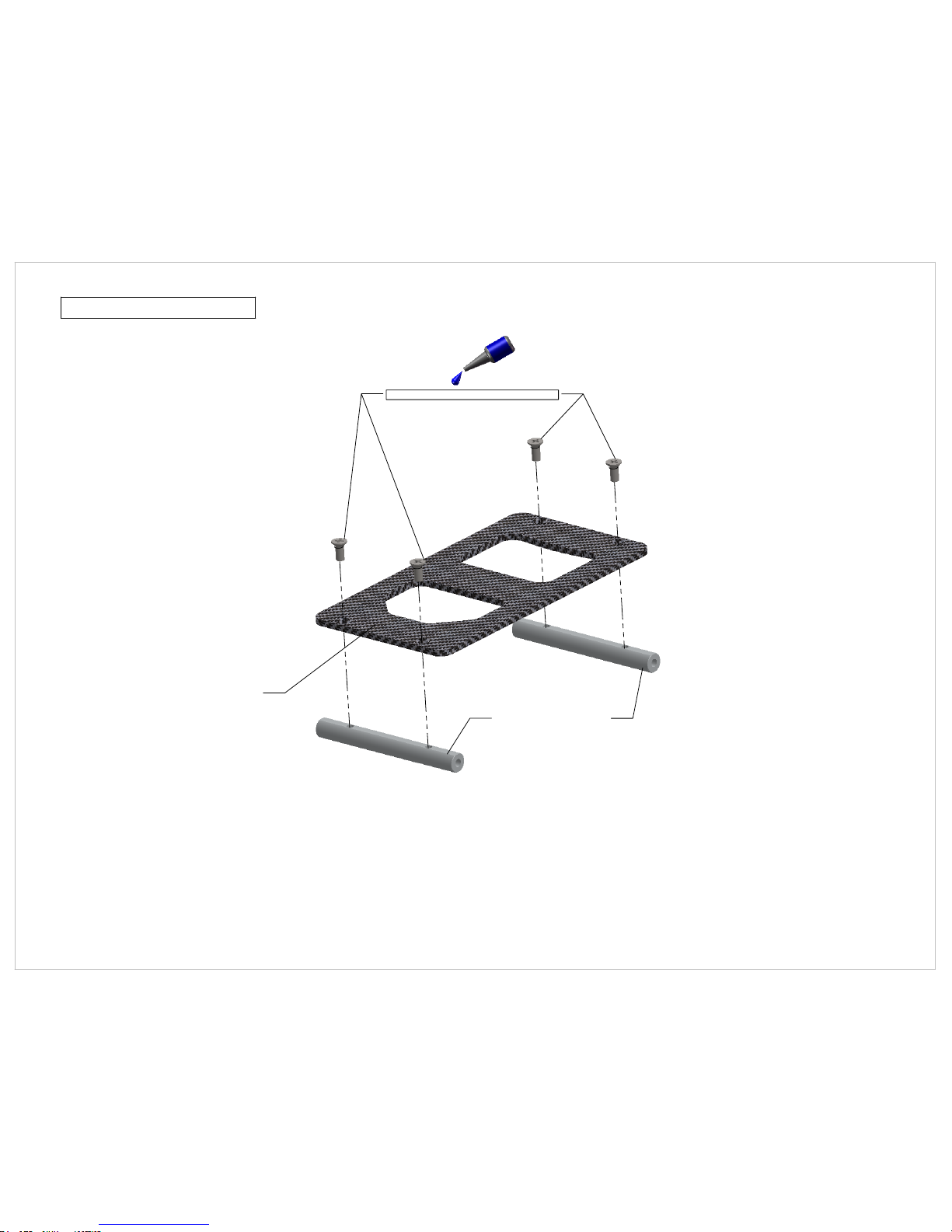
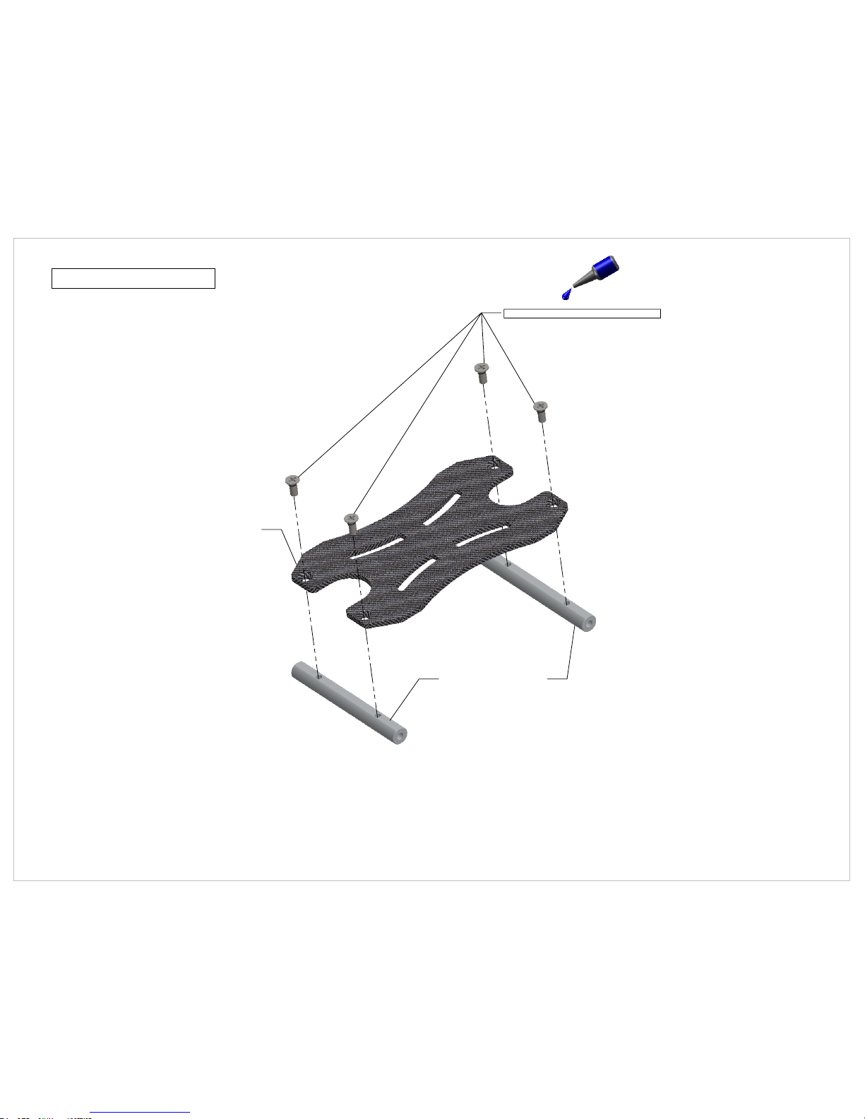
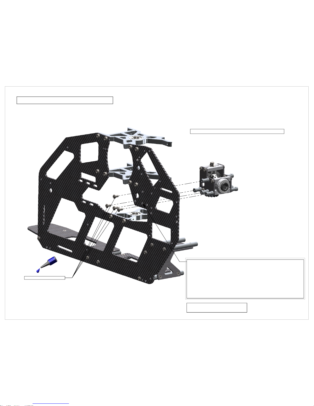
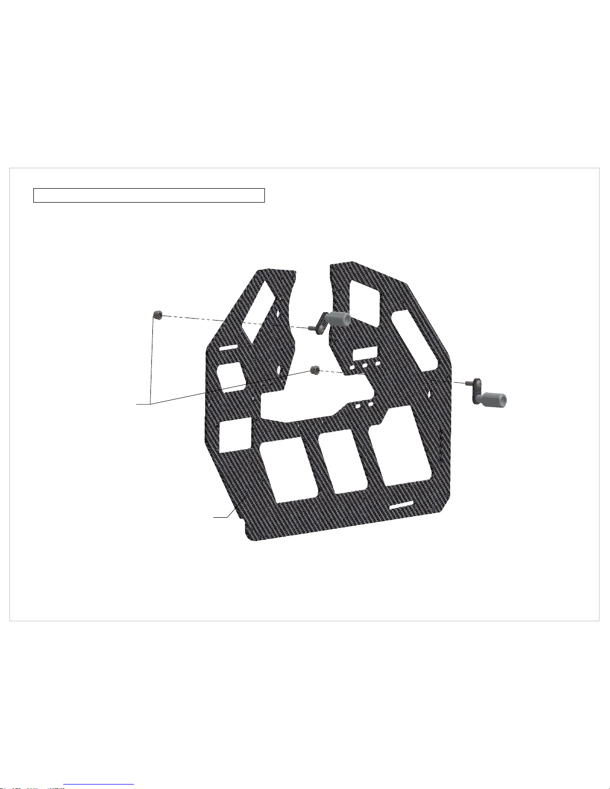
103-256 M2.5 Flat Head Cross Recess
305-102 CF Lower Frame Brace
305-101 E5 Frame Spacer
103-256 M2.5 Flat Head Cross Recess
305-103 E5 CF Gyro Mount Plate
305-101 E5 Frame Spacer
Lower Frame Brace Assembly
Page 1
Gyro Mount Plate Assembly
WWW.SYNERGYRCHELICOPTERS.COM
Page 4
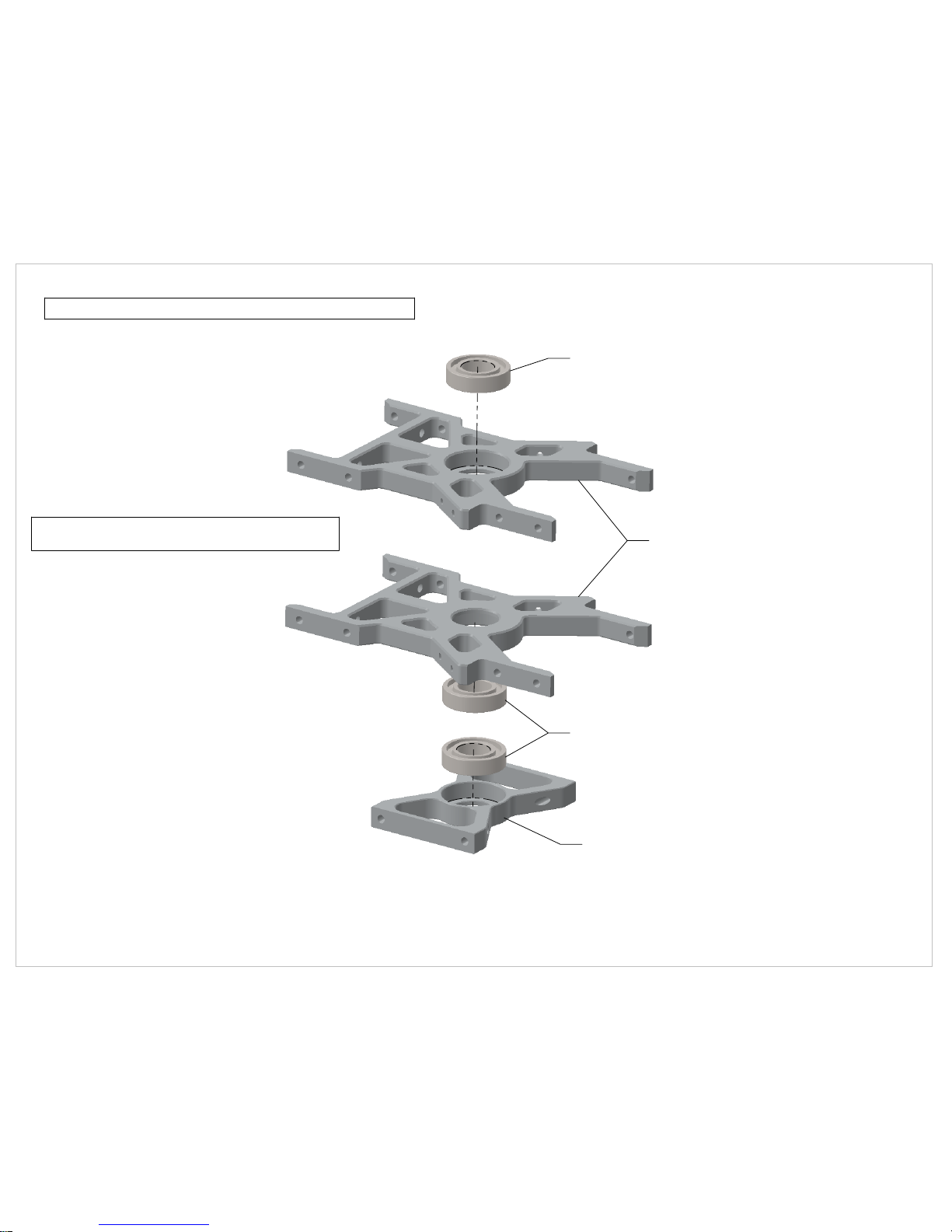
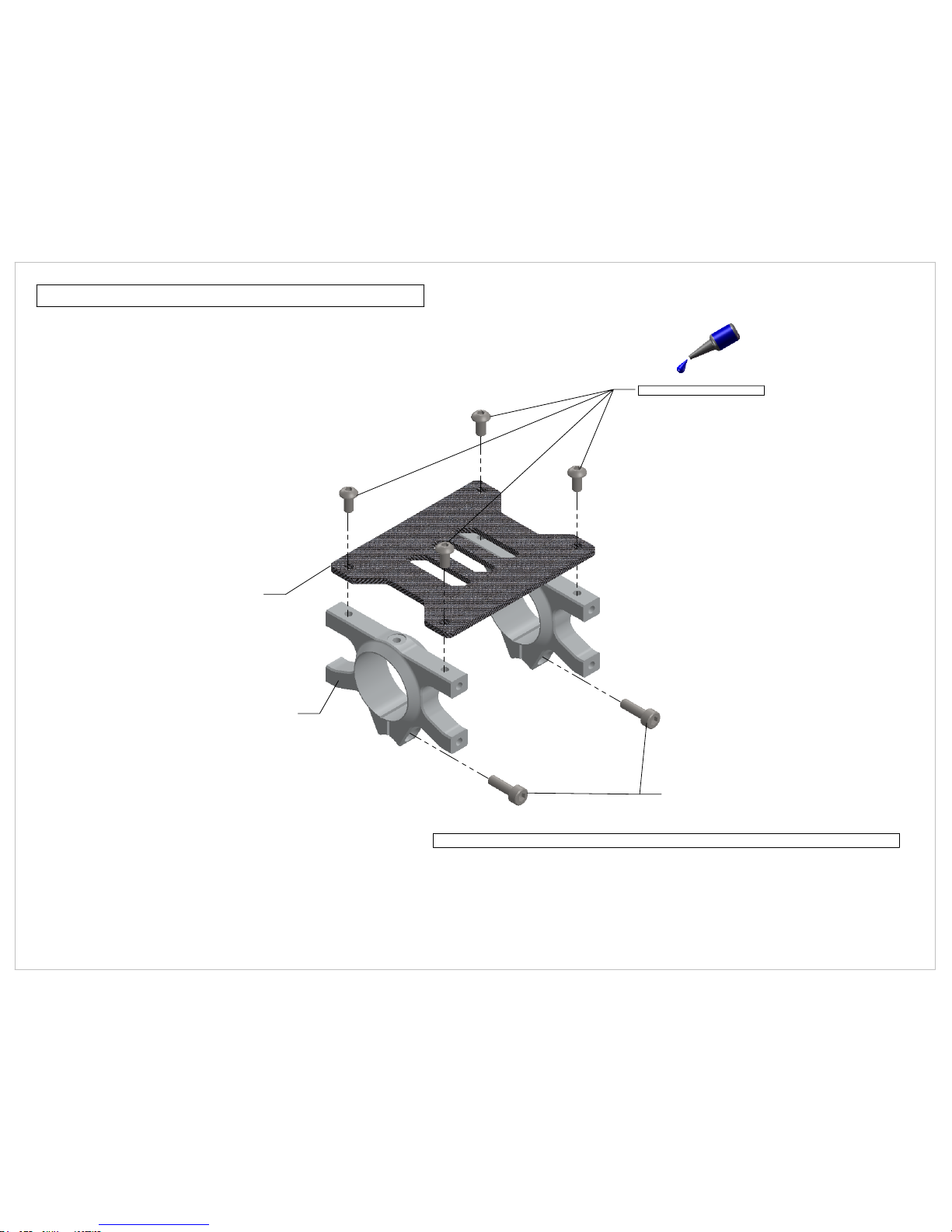
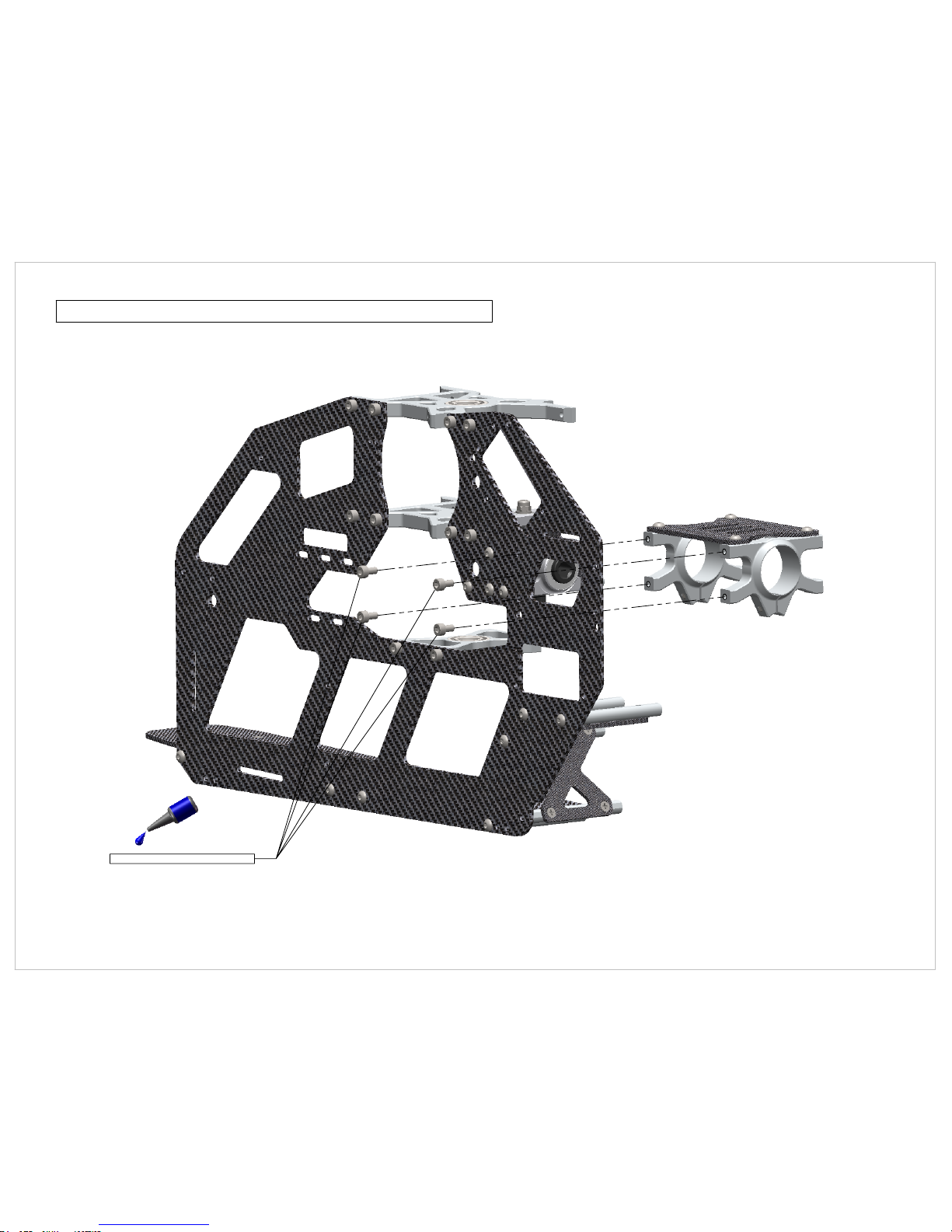
108-105 - 10x19x5 Radial Bearing
108-105 - 10x19x5 Radial Bearing
305-104 E5 Third Main Shaft Bearing Block
305-124 E5 Main Shaft Bearing Block
Main Shaft Bearing Block Assembly
*** Note ***
Observe orientation of bearing blocks
Page 2
WWW.SYNERGYRCHELICOPTERS.COM
Page 5
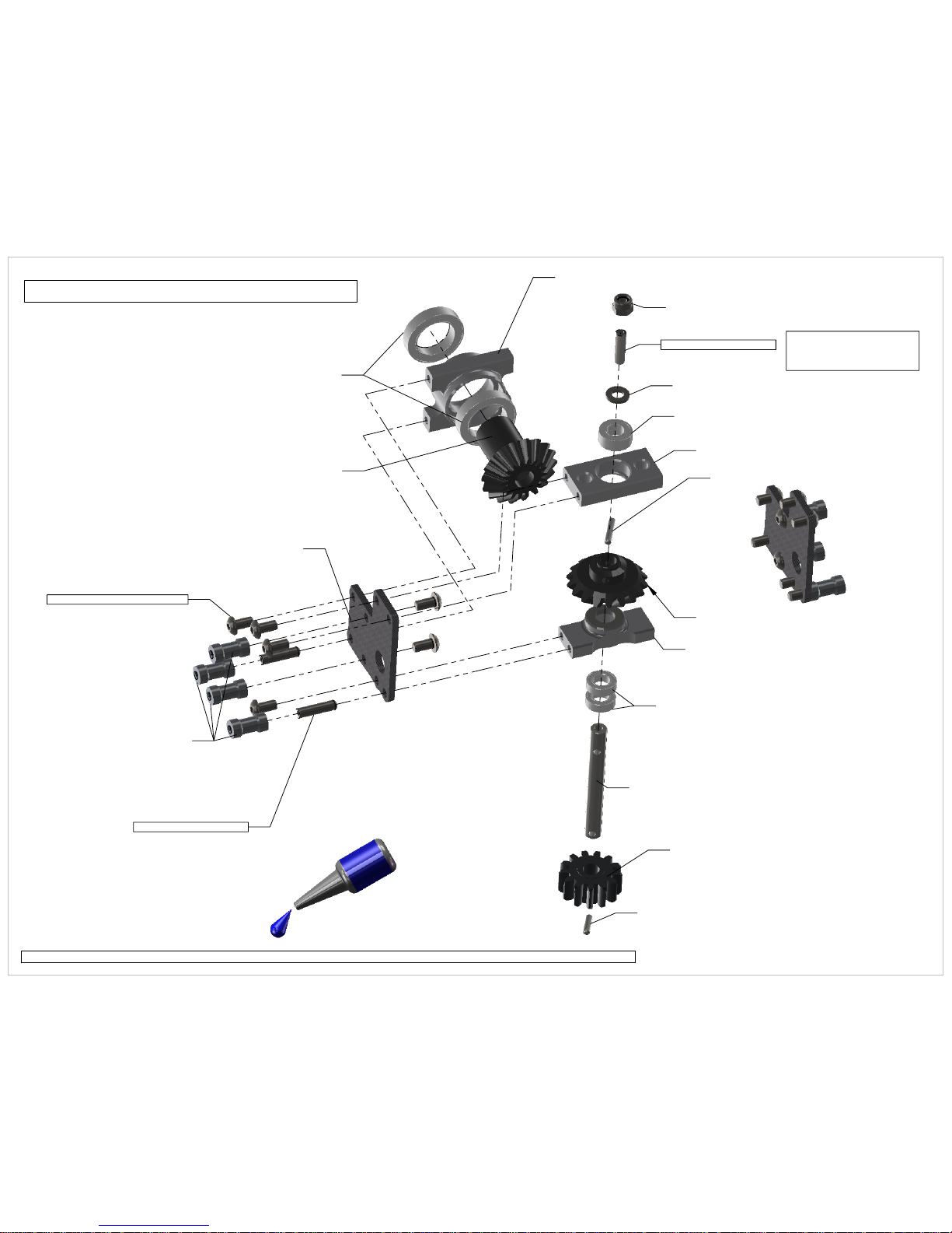
Front Tail Transmission Assembly
108-124 12x18x4 Radial Bearing
320-301 Front Mushroom Gear Bearing Block
320-218 18T Front Trans Mushroom Gear
100-351 M3 Nylock Nut
100-372 M3x12 Set Screw
100-354 M3 Washer
108-510 5x10x4 Radial Bearing
320-302 Bevel Gear Top Bearing Block
320-406 11mm Pin for 18T Bevel Gear
320-303 Spur Gear Bottom Bearing Block
108-593 5x9x3 Radial Bearing
320-408 Spur Gear Shaft
305-213 13T Spur Gear
320-407 2mm Spur Gear Pin
320-101 TranSupport CF Plate
305-105 E5 TranSupport Standoff
101-306 M3x6 Button Head x12
100-372 M3x12 Set Screw
Important! - TIghten and
secure set screw with loctite.
This set screw secures bevel
gear pin.
Page 3
320-118 Front Trans Bevel Gear
IMPORTANT! - Any screw which is metal to metal needs loctite! Clean oil from bolts and apply blue loctite.
Page 6
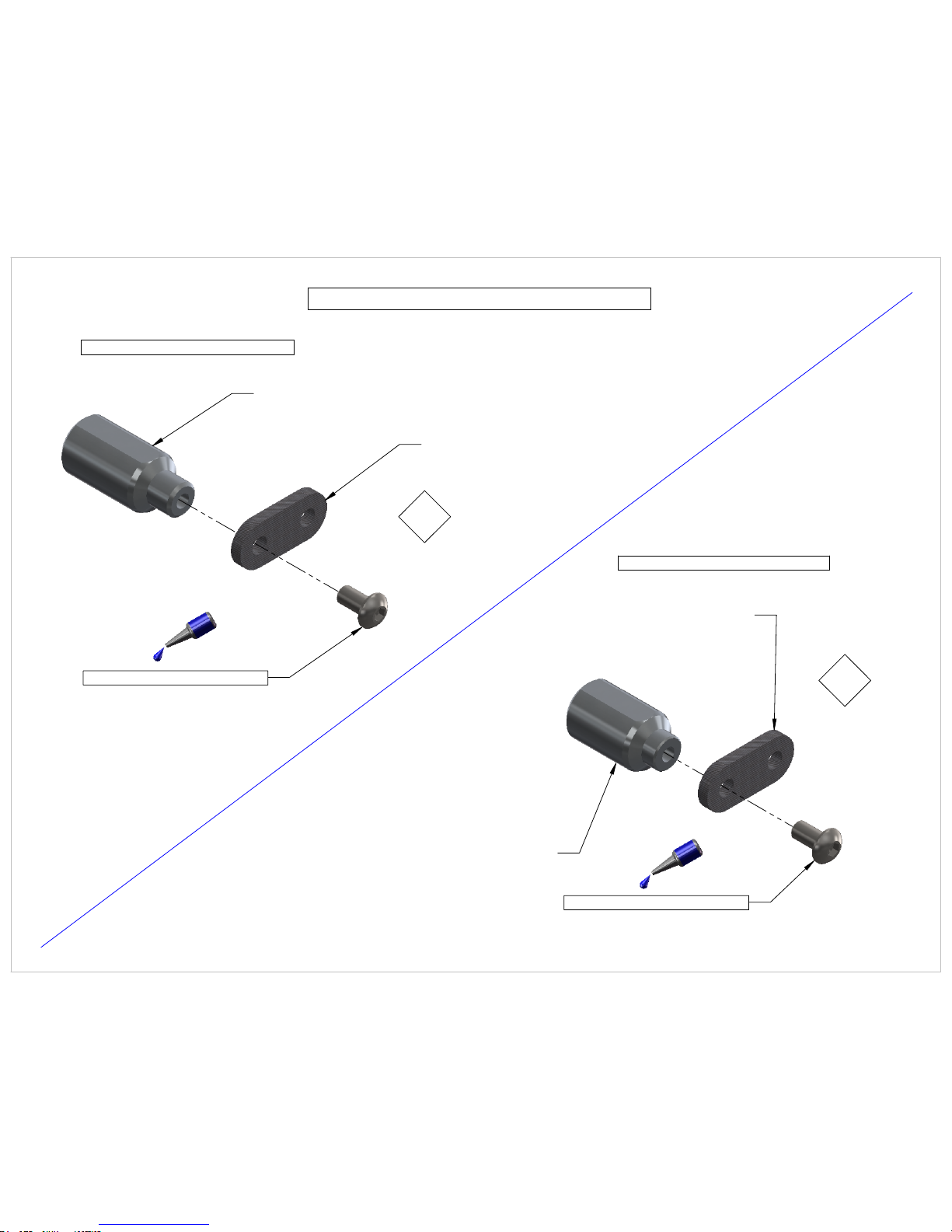
305-121 Key Chain Canopy Mount, Female 21mm
305-106 Break-away Plate
101-306 M3x6 Button Head
X2
Front Canopy Mounts (21mm)
101-306 M3x6 Button Head
305-117 Key Chain Canopy Mount, Female 17mm
305-106 Break-away Plate
Key Chain Style Canopy Mounts
X2
Rear Canopy Mounts (17mm)
Page 4
WWW.SYNERGYRCHELICOPTERS.COM
Page 7

103-256 M2.5 Flat Head Cross Recess
305-101 E5 Frame Spacer
305-107 Front Battery Plate
Front Battery Plate
Page 5
WWW.SYNERGYRCHELICOPTERS.COM
Page 8
103-256 M2.5 Flat Head Cross Recess
305-101 E5 Frame Spacer
305-108 E5 Rear Battery Plate
Rear Battery Plate
Page 6
WWW.SYNERGYRCHELICOPTERS.COM
Page 9
103-256 M2.5 Flat Head Cross Recess
305-101 E5 Frame Spacer
305-109 E5 ESC Mount Plate
ESC Mount Plate
Page 7
WWW.SYNERGYRCHELICOPTERS.COM
Page 10
101-306 M3x6 Button Head
100-310 M3x10 Socket Head
305-111 E5 Main Boom Clamp
305-110 E5 Radio Plate
Main Boom Clamps and Radio Plate
Note - Bolts engaged in pinching mechanism do not require loctite
Page 8
WWW.SYNERGYRCHELICOPTERS.COM
Page 11
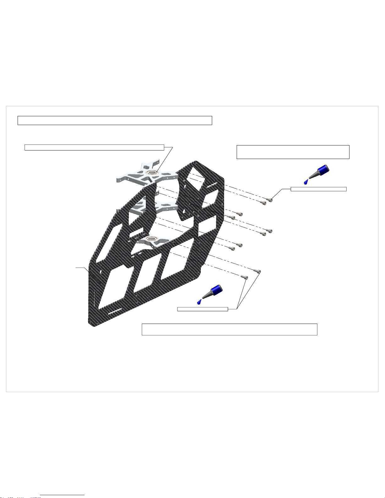
100-306 M3x6 Socket Head x8
100-308 M3x8 Socket Head
Left Frame - Main Shaft Bearing Blocks - Install
ATTENTION!
DO NOT FULLY TIGHTEN BOLTS YET!!
Note - Third Main Shaft Bearing Block is adjustable fore and aft
to provide for correct main shaft alignment.
Note - Pay attention to bearing block orientation!
305-118 E5 Main Frame CF
Page 9
WWW.SYNERGYRCHELICOPTERS.COM
Page 12
Battery Plate - Install
101-306 M3x6 Button Head
NOTE - DO NOT FULLY TIGHTEN BOLTS YET!
Page 10
WWW.SYNERGYRCHELICOPTERS.COM
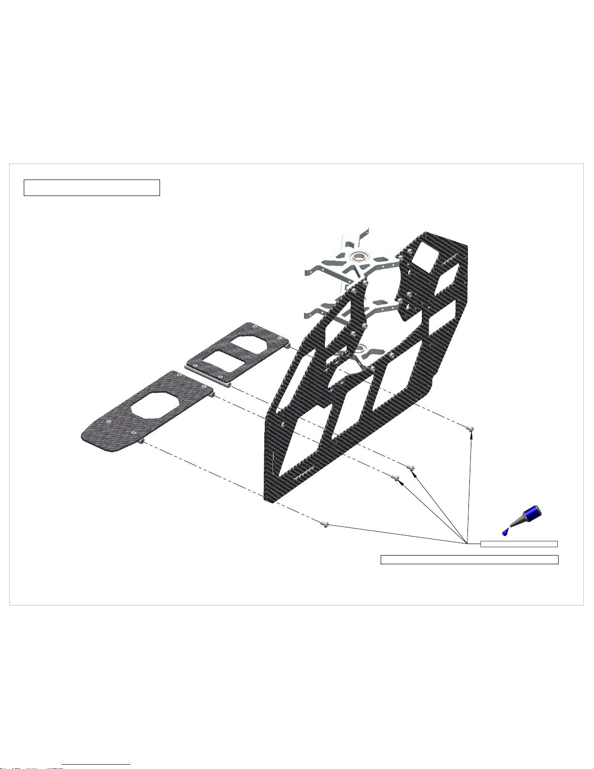
Page 13
101-306 M3x6 Button Head
NOTE - DO NOT FULLY TIGHTEN BOLTS
Gyro Plate and Lower X Brace - Install
Page 11
WWW.SYNERGYRCHELICOPTERS.COM
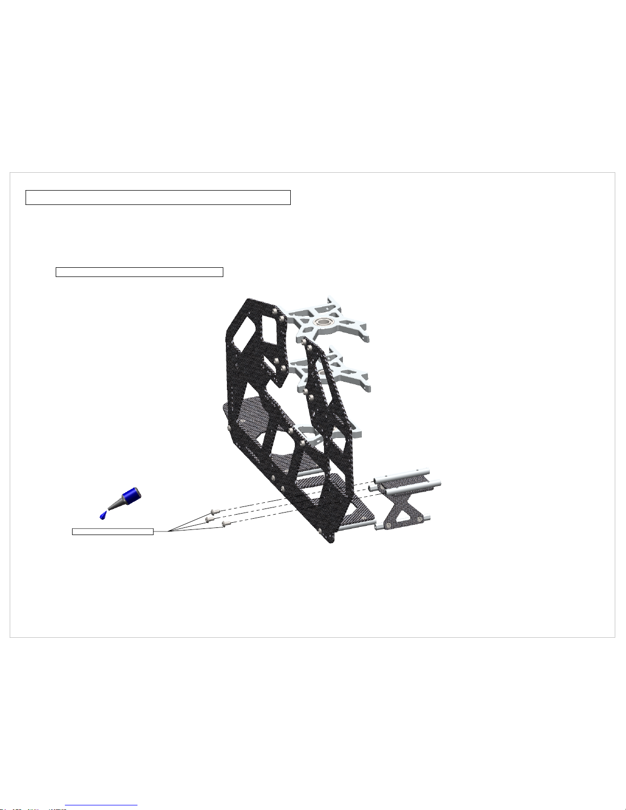
Page 14
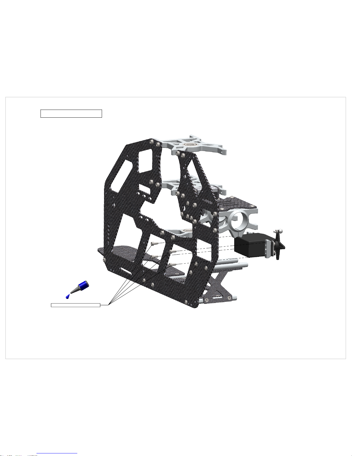
101-306 M3x6 Button Head
Front Tail Transmission Install
NOTE - DO NOT TIGHTEN BOLTS FULLY YET!
**IMPORTANT PLEASE READ**
Frames are slotted for optional tail gear ratios
Tail Transmission was designed to slide
fore and aft to allow for 4.0:1 gear ratio
as well as optional 4.5:1 tail ratio.
4.0:1(stock)Slide Transmission all the way FORWARD
4.5:1(optional)Slide Transmission all the way AFT
4.0:1 = 52T / 13T (Stock)
4.5:1 = 54T / 12T (Optional)
Page 12
WWW.SYNERGYRCHELICOPTERS.COM
Page 15
Main Boom Clamp and Radio Plate Install
100-306 M3x6 Socket Head Bolt
Page 13
WWW.SYNERGYRCHELICOPTERS.COM
Page 16
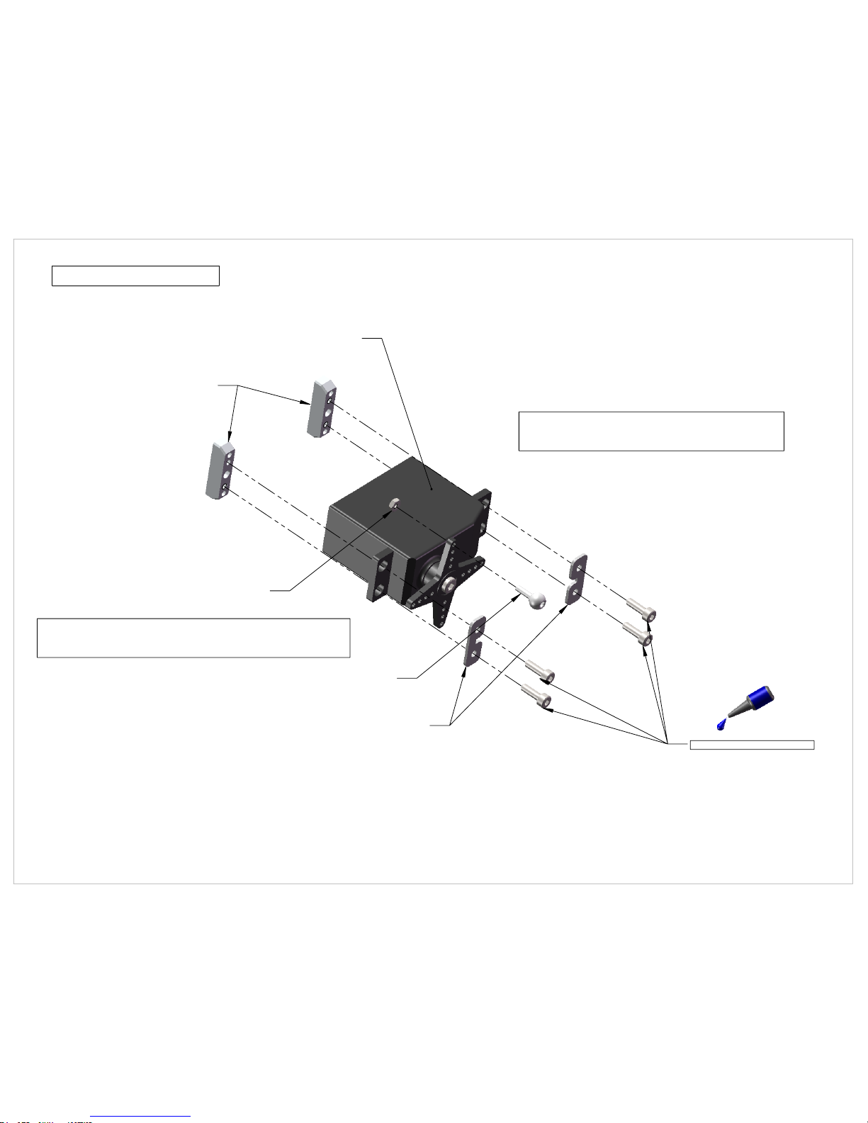
305-112 Elevator Tail Servo Mount
High Quality Digital 760us Tail Servo (Not Included)
Recommended - Futaba BLS256
100-268 M2.5x8 Socket Head
106-115 Servo Hold Down
107-104 Pivot Ball 2mm
100-252 M2 Nylock Nut
Note - Servo horn will need to be trimmed
in order to avoid interference with gyro
sensor mount.
Important - Pivot ball should be located at
16mm from center of servo horn. This is important
for proper servo resolution.
Tail Servo Mount
Page 14
WWW.SYNERGYRCHELICOPTERS.COM
Page 17
100-266 M2.5x6 Socket Head
Tail Servo Install
Page 15
WWW.SYNERGYRCHELICOPTERS.COM
Page 18

Canopy Mount Install - Left Frame Side
101-310 M3x10 Button Head
100-351 M3 Nylock Nut
21mm Front Canopy Mount
See Page 4
17mm Rear Canopy Mount Assembly
See Page 4
Note - Button Head fits into large frame hole, mounts will fit flush against frame.
305-101 E5 Frame Spacer
101-306 M3x6 Button Head
Page 16
WWW.SYNERGYRCHELICOPTERS.COM
Page 19
100-351 M3 Nylock Nut
305-118 E5 Main Frame CF
Page 17
WWW.SYNERGYRCHELICOPTERS.COM
Right Frame Canopy Mount Install
Page 20

Elevator Servo Mounting
100-268 M2.5x8 Socket Head
100-266 M2.5x6 Socket Head
106-115 Servo Hold Down x2
305-112 Elevator-Tail Servo Mount X2
Page 18
WWW.SYNERGYRCHELICOPTERS.COM
Page 21

Right Frame Install - Socket Head Bolts
100-306 M3x6 Socket Head
100-308 M3x8 Socket Head
DO NOT TIGHTEN BOLTS YET!
Page 19
WWW.SYNERGYRCHELICOPTERS.COM
Page 22

Right Frame Install - Button Head Bolts
101-306 M3x6 Button Head Bolt x12
Page 20
WWW.SYNERGYRCHELICOPTERS.COM
Page 23

Frame Alignment - Anti Rotation Bracket Install
101-306 M3x6 Button Head
Use E5 Main Shaft to align bearing blocks
Note - Third bearing block is adjustable fore/aft
to allow for better alignment of bearing blocks.
Tighten all frame bolts fully once you are satisfied
with frame alignment. Tighten Anti-Rotation
Bracket bolts last.
305-120 E5 Anti-Rotation Bracket
90.00°
FLAT SURFACE
Page 21
WWW.SYNERGYRCHELICOPTERS.COM
Page 24

Landing Gear Mounts
305-122 E5 Landing Gear Mount
101-306 M3x6 Button Head
Page 22
WWW.SYNERGYRCHELICOPTERS.COM
Page 25

305-123 E5 Skid Tube
106-966 Skid Tube Plug
610-324 Landing Gear Strut
610-322 Skid Tube Lock
101-308 M3x8 Button Head
Note - Alternatively if you find the Skid Tube Locks
too difficult, you can use M4x6 Set Screws to secure
the E5 Skid Tube.
Landing Gear Assembly
Page 23
WWW.SYNERGYRCHELICOPTERS.COM
Page 26

Landing Gear Install
100-312 M3x12 Socket Head x4
Page 24
WWW.SYNERGYRCHELICOPTERS.COM
Page 27

Auto Hub Bronze Bushing
Auto Hub
One Way Clutch Bearing
Auto Hub Bronze Bushing
DO NOT USE GREASE ON ONE-WAY!!
USE LIGHT OIL SUCH AS TRIFLOW!
Auto Hub Assembly
200-407 - Auto Hub Assembly
Important - Bronze bushings must be secured
with green or red loctite!
Note - By design the auto hub is symetrical so it can
be used in both orientations. The One-Way Clutch Bearing
can be pressed into the Auto Hub in any direction. Please
pay attention to motor direction and insert auto hub sleeve
in the correct orientation.
Important - Bronze bushings must be secured
with green or red loctite!
Page 25
WWW.SYNERGYRCHELICOPTERS.COM
Page 28

320-410 Spur Gear Hub
305-152 52T Spur Gear
103-256 M2.5x6 Cross Recess
305-119 119T Main Gear
101-308 M3x8 Button Head x4
610-151 Auto Hub Delrin Shim
200-407 Auto Hub Assembly
610-151 Auto Hub Delrin Shim
610-147 Auto Hub Sleeve
Note - Do not use grease inside
auto hub assembly. Please use
light oil such as Triflow.
IMPORTANT - PLEASE READ!!!
Reverse
Orientation
Factory Auto Hub Orientation
Main Gear and Spur Gear Assembly
IMPORTANT! - Do not over tghten bolts.
You may crack delrin gears by over tightening.
Note - By design the auto hub is symmetrical so it can
be used in both orientations. The One-Way Clutch Bearing
can be pressed into the Auto Hub in any direction. Please
pay attention to motor direction and insert auto hub sleeve
in the correct orientation. Your auto hub may be assembled
opposite from the picture. This is perfectly normal!!! Do not
attempt to press the one way bearing out of the auto hub!
IMPORTANT - PLEASE READ!!!
Page 26
WWW.SYNERGYRCHELICOPTERS.COM
Page 29

610-150 Pinch Collar
100-261 M2.5x10 Socket Head
100-320A M3x20 Shouldered
100-325A M3x25 Shouldered
320-411 Jesus Bolt Collar
100-351 M3 Nylock Nut
305-140 E5 Main Shaft
IMPORTANT!
Pinch collar has a boss which should be oriented facing
down against the inner race of the main shaft bearing.
IMPORTANT! -
Boss on Jesus bolt collar should be facing
upward! Failure to orient upward will result
in excessive verticle movement in the main
shaft
Main Gear Transmission Installation
IMPORTANT!
- Do not over tighten
shouldered bolts. This will distort auto
hub sleeve which will cause auto hub
problems.
Page 27
WWW.SYNERGYRCHELICOPTERS.COM
Page 30

108-615 6x15x5 Radial Bearing
305-114 E5 Pinion Support Bearing Block
Motor Pinion Support Bearing Block
Page 28
WWW.SYNERGYRCHELICOPTERS.COM
Page 31

100-312 M3x12 Socket Head
305-113 E5 Motor Mount
Scorpion Motor (Not Included)
Pinion Options
305-012 - E5 12T Pinion (Included)
305-013 - E5 13T Pinion (Option)
305-014 - E5 14T Pinion (Included)
305-015 - E5 15T Pinion (Option)
100-466 M4x6 Set Screw
Motor Mount Assembly
The Synergy E5 has a 52mm inner frame width and
a motor mount that accepts 25mmx3mm or 30mmx4
mount patterns. This means that the E5 is one of the
most configurable helicopters on the market today!
With parts already available you can also stretch your
E5 to accept 600mm rotor blades. The battery compartment
will accept many pack configurations from 6S to 12S.
Pinion options range from 12T to 15T.
Motor Recommendation for E5 - 550 Class
6S - Scorpion 4025-1100
12S - Scorpion 4025-630
Motor Recommendations for E5s - 600 Class
10S - Scorpion 4035-630
12S - Scorpion 4035-560
Note - Do not fully tighten pinion set screw yet!
Page 29
WWW.SYNERGYRCHELICOPTERS.COM
Page 32

Motor Installation
100-310 M3x10 Socket Head x10
305-116 E5 Pinion Support CF Washer
305-115 E5 Motor Mount CF Washer
Note - Assemble both sides
of motor mount to frame assembly
IMPORTANT!- Pinion must rest on lower pinion
support radial bearing. If configured otherwise
you may destroy motor bearings.
Helical Gear Mesh - Set gear mesh
with minimal lash but do not set for
zero lash. High pressure grease is
recommended for smooth operation.
Page 30
WWW.SYNERGYRCHELICOPTERS.COM
Page 33

ESC Mount Plate Install
101-306 M3x6 Button Head x4
Recommended ESC - ICE2 HV120
Note - 6S Helicopters are low voltage / high current
models. Current draw can be very high depending
on your configuration. Choose an ESC that is adequate
for your configuration.
Important Tips!
- Use quality 60/40 rosin core solder with a high temp soldering iron
- Do not allow motor or ESC wires to interfere with carbon frames
Page 31
WWW.SYNERGYRCHELICOPTERS.COM
Page 34

320-504 O-Ring
320-503 Torque Tube Bearing Housing
108-814 8x14x4 Radial Bearing
320-502 Torque Tube End
100-212 M2x12 Socket Head
100-252 M2 Nylock Nut
305-301 E5 Torque Tube
Torque Tube Assembly
IMPORTANT! - Secure Torque Tube End with Red Loctite!
190mm
7 1/2 Inches
190mm
7 1/2 Inches
Secure bearing to Torque Tube with Red Loctite or CA
Bearing must be installed before Torque Tube end as the
bearing will not slide over the Torque Tube End.
Page 32
WWW.SYNERGYRCHELICOPTERS.COM
Page 35

6.500
3mm
1/8 inch
Tail Boom Bolt Hole
(Optional but highly recommended)
Drill 3mm hole at 6.5mm from edge of tail boom.
Note - Synergy boom clamps have proven to be adequte for securing the tail boom for
most helicopter pilots. As an added precaution you may pin the boom with a 3mm bolt.
Page 33
WWW.SYNERGYRCHELICOPTERS.COM
Page 36

Torque Tube Assembly (Page 32)
115-114 Tail Control Guide
610-128 Boom Support Clamp, Lite
115-114 Tail Control Guide
305-302 E5 Tail Boom
100-312 M3x12 Socket Head
Note - CA May be required to
secure Tail Control Guide to Tail Boom
Tail Boom Assembly
Page 34
WWW.SYNERGYRCHELICOPTERS.COM
Page 37

305-303 E5 Boom Support Rod
115-119 Boom Support End
115-119 Boom Support End
Notes -
1. Use Epoxy or JBWeld
2. Ensure ends are in alignment while glue sets
Top - attaches to boom clamp
Bottom - attaches to frames
Sand Ends Lightly Before
applying glue!
Sand Ends lightly before
applying glue!
Boom Support Assembly
109-345 3x4x5 Brass Spacer
Page 35
WWW.SYNERGYRCHELICOPTERS.COM
Page 38

Tail Boom & Boom Support Install
101-306 M3x6 Button Head
100-316 M3x16 Socket Head
100-354 M3 Washer
101-410 M4x10 Button Head
Optional if hole is drilled
IMPORTANT!
DO NOT SLIDE TAIL BOOM FORWARD ANY MORE
THAN FLUSH WITH FRONT BOOM CLAMP!! THIS CAN
PLACE PRESSURE ON TRANSMISSION GEAR MESH!!
Boom Support Assembly (page 35)
Tail Boom Assembly (page 34)
Page 36
WWW.SYNERGYRCHELICOPTERS.COM
Page 39

100-306 M3x6 Socket Head
100-354 M3 Washer
108-503 5x10x3 Radial
106-501 5mm Shim
Small OD Small ID
Large ID Large OD
Ball Race
515-525 Tail Blade Grip
108-503 5x10x3 Radial
107-106 Pivot Ball
108-511 5x10x4 Thrust Bearing
IMPORTANT! - Apply Grease to Thrust Bearing Ball Race
615-324 Tail Rotor Hub (for 6mm shaft)
Tail Rotor Hub Assembly
Page 37
WWW.SYNERGYRCHELICOPTERS.COM
Page 40

Pitch Slider Assembly
615-319 Tail Pitch Slider Bushing (for 6mm shaft)
108-812 8x12x2.5 Radial Bearing
107-103 2mm Pivot Ball Short
115-319 Tail Bearing Ring
108-812 8x12x2.5 Radial Bearing
115-322 Tail Pitch Link
106-813 Tail Slider Lock Ring
606-921 Tail Pitch Link Pin
506-920 E-Ring
115-321 Pitch Plate
Use Medium CA to secure 2mm pivot ball
1. After installing lock ring be sure that the
radial bearings do not have lateral load
on them. Adjust lock ring as needed to
ensure smooth operation.
2. Secure lock ring with CA or Epoxy
Red Loctite Tail Pitch Slider to Tail
Pitch Plate for extra security.
Page 38
WWW.SYNERGYRCHELICOPTERS.COM
Page 41

305-309 E5 Tail Box
108-124 12x18x4 Radial Bearing
320-405 Tail Box Bearing Spacer
101-306 M3x6 Button Head
108-613 6x13x5 Raidal Bearing
305-307 E5 Output Shaft Spacer
615-124 Tail Output Shaft 6mm
305-308 E5 Tail Box Spacer
305-618 E5 18T Mushroom Tail Bevel Gear
305-518 E5 18T Tail Bevel Gear
305-304 E5 Verticle Tail Fin CF
305-305 E5 Tail Box Plate Left
305-306 Tail Box Plate Right
108-613 6x13x5 Radial Bearing
101-306 M3x6 Button Head
100-325 M3x25 Socket Head
100-306 M3x6 Socket Head
100-366 M3x6 Set Screw
Tail Box Assembly
Page 39
WWW.SYNERGYRCHELICOPTERS.COM
Page 42

100-351 M3 nylock Nut
305-310 E5 Tail Lever Mount
101-308 M3x8 Button Head
106-301 M3 Shim
108-373 3x7x3 Radial Bearing
109-355 3x5x5 Brass Spacer
Tail Rotor Bell Crank
108-373 3x7x3 Radial Bearing
100-330 M3x30 Socket Head
107-104 2mm Pivot Ball
100-251 M2 Nut
Tail Rotor Bell Crank Assembly
Page 40
WWW.SYNERGYRCHELICOPTERS.COM
Page 43

100-464 M4x4 Set Screw
Note - Sizing of ball links is recommended
for smooth operation. For best results use
Boto-Sizer Tool Part #700-001
Tail Box Completion
Page 41
WWW.SYNERGYRCHELICOPTERS.COM
Page 44

Tail Box Install
101-306 M3x6 Button Head
IMPORTANT!
If you wish to use boom pinning feature
you must drill 3mm hole! Follow these steps.
Install Tail Box
1.
Ensure Tail Box is vertical
2.
Mark drill location
3.
Remove tail box and torque tube
4.
Drill 3mm hole at marked location
5.
Page 42
WWW.SYNERGYRCHELICOPTERS.COM
Page 45

107-100 Ball Link
305-311 Tail Push Rod End
106-965 Tail Push Rod Sleeve (Teflon)
305-565 E5 Tail Control Rod 565mm
IMPORTANT! - Tail Control Rod End must be secured with
high quality glue such as JB Weld. We highly recommend
long curing formulas for the best results. Do not use CA for
this application! You will encounter failures!
Note - Lightly sand carbon tail
control rod prior to securing with
JB Weld!
Note - Tail push rod ends will slide through
tail control guides.
Tail Control Rod Assembly
Page 43
WWW.SYNERGYRCHELICOPTERS.COM
Page 46

107-100 Ball Link
Tail Control Rod Install
Note - Adjust ball links so tail rotor bell crank is 90 degrees
to tail box while tail servo arm is perfectly vertical. This will
automatically configure 5 degree torque compensation at
tail rotor blades.
Page 43B
WWW.SYNERGYRCHELICOPTERS.COM
Page 47

Swash Plate Assembly
107-108 Pivot Ball Long x3
107-106 Pivot Ball x4
108-373 3x7x3 Radial Bearing
100-316 M3x16 Socket Head
109-352 3x5x2 Brass Spacer
100-312 M3x12 Socket Head
100-364 M3x4 Set Screw
200-401 Swash Plate Assembly
WWW.SYNERGYRCHELICOPTERS.COM
Page 44
Page 48

100-512 M5x12 Socket Head
100-554 M5 Washer
108-816 8x16x5 Radial Bearing
106-801 8x0.5 Washer
108-816 8x16x5 Thrust Bearing
310-144 Blade Bolt Adapter 4mm
108-816 8x16x5 Radial Bearing
106-803 8x1mm Washer
606-803 Solid Head Damper
310-144 Blade Bolt Adapter 4mm
305-201 E5 Head Block
305-205 E5 Head Axle
305-203 E5 Pitch Arm
305-204 E5 Axle Pivot
100-308 M3x8 Socket Head
100-306 M3x6 Socket Head
107-106 Pivot Ball 3x4.5mm
Small OD / Small ID
Ball Race
Large OD / Large ID
Important - Apply grease to thrust bearing ball race
305-202 E5 Blade Grip
Grease Port
Thrust Bearings can be greased by
utilizing the external "Grease Port"
Head Block and Blade Grip Assembly
Synergy Grease Port
Page 45
WWW.SYNERGYRCHELICOPTERS.COM
Page 49

Swash Follower Arm Assembly
106-301 M3 Shim
108-383 3x8x3 Radial Bearing
305-206 E5 Washout Control Arm
109-352 3x5x2 Brass Spacer
108-383 3x8x3 Radial Bearing
108-383 3x8x3 Radial Bearing
100-323 M3x23 Socket Head
100-316 M3x16 Socket Head
109-352 3x5x2 Brass Spacer
108-383 3x8x3 Radial Bearing
107-100 Ball Link
100-272 M2.5x12 Set Screw
305-207 E5 Ball Link Adapter
106-301 M3 Shim
Note - Do not tighten 100-323 bolt until the
next page. These will pinch and secure the
main shaft.
Page 46
WWW.SYNERGYRCHELICOPTERS.COM
IMPORTANT!
Remove M2.5x12 Set Screw from Ball Link Adapter
before attempting to remove M3x16 Socket Head.
The M2.5x2 Set Screw is sitting against the M3x16
bolt and will destroy the bolt threads and the Ball
Link Adapter threads if you attempt to remove the
bolt without rst removing the set screw.
Page 50

Rotor Head Install
100-320A 3x20 Shouldered Bolt
100-351 M3 Nylock Nut
IMPORTANT!
Do not over tighten 100-320A Bolt!
IMPORTANT!
Do not forget to tighten pinch bolts!
Page 47
WWW.SYNERGYRCHELICOPTERS.COM
Page 51

Pitch Link Assembly
X2
Note 700-100 Boto-Sizer Tool is highly recommended
for smooth linkage operation.
28mm
107-100 Ball Link
107-043 43mm Rod
Page 48
WWW.SYNERGYRCHELICOPTERS.COM
Page 52

Aileron and Pitch Servo Install
100-261 M2.5x10 Socket Head
106-115 Servo Hold Down
106-115 Servo Hold Down
Page 49
WWW.SYNERGYRCHELICOPTERS.COM
Page 53

100-352 M3 Nut
107-106 Pivot Ball
100-251 M2 Nut
100-206 M2x6 Socket head
310-107 CF Servo Arm
IMPORTANT! - Use Red Loctite to
secure Pivot Ball to M3 Nut
Servo Horn Assembly
Note - It is best to determine servo horn position
clostest to 90 degrees before fixing CF servo arm
to the servo arm wheel.
Page 50
WWW.SYNERGYRCHELICOPTERS.COM
Page 54

Servo Arm Install
Page 51
WWW.SYNERGYRCHELICOPTERS.COM
Page 55

Alignment Holes
Alignment Holes
Servo Horn Alignment Holes
Page 52
WWW.SYNERGYRCHELICOPTERS.COM
Page 56

Cyclic Link Assembly
X3
19.30mm
107-100 Ball Link
107-043 43mm Rod
Page 53
WWW.SYNERGYRCHELICOPTERS.COM
Page 57

Rotor Blade Install
100-435A M4x35 Shouldered Bolt
100-451 M4 Nylock Nut
Rotor Blades Not Included
For optimum performance
use Rail 556mm rotor blades.
Page 54
WWW.SYNERGYRCHELICOPTERS.COM
Page 58

Rail 96mm Tail Blade
(Not Included)
100-316 M3x16 Socket Head
305-312 Tail Blade Washers x2
305-312 Tail Blade Washers x2
100-351 M3 Nylock Nut
100-351 M3 Nylock Nut
Tail Blade Install
Note - Counter clockwise rotating tail.
Install tail blades as illustrated.
Page 55
WWW.SYNERGYRCHELICOPTERS.COM
Page 59

305-125 Key Chain Canopy Mount Male
305-126 Key Chain Canopy Grommet
Note - Canopy holes may need enlarged to
approximately 8-9mm in order to correctly install
the canopy rubber grommet.
305-125 Key Chain Canopy Mount Male
Canopy Assembly
Page 56
WWW.SYNERGYRCHELICOPTERS.COM
Page 60

Synergy E5 - Completed!
Page 57
WWW.SYNERGYRCHELICOPTERS.COM
Page 61

1253.500
Main Rotor Diameter
Rotor Disk with 556mm blades - 1253.50mm
Rotor Disk with 606mm blades - 1353.50mm (configured with E6 boom)
Page 58
WWW.SYNERGYRCHELICOPTERS.COM
Page 62

258
Tail Rotor Diameter
Page 59
WWW.SYNERGYRCHELICOPTERS.COM
Page 63

1085mm
214mm
360mm
Synergy E5 - Dimensions
Page 60
WWW.SYNERGYRCHELICOPTERS.COM
 Loading...