

Page 1
SYNERGY MFG. 870 INDUSTRIAL WAY, SAN LUIS OBISPO, CA (805) 242-0397
8562 DODGE AAM INNER AXLE SLEEVES
GENERAL NOTES:
These instructions are also available on our website; www.synergymfg.com. Check the website before
you begin for any updated instructions and additional photos for your reference.
The installation of the inner axle sleeves requires removal of wheels, brakes, axle shafts and axle
housing assembly.
Installation of the sleeves requires drilling ½” holes at various places on the axle housing.
A competent welder is needed for completing the plug welds and circular welds around the axle housing
tube for proper installation.
It is recommended to remove the axle housing completely; this will make drilling and welding much
easier.
It is not necessary to remove the differential and gears or even drain the oil. Just be careful to not let
metal chips in the differential housing when drilling the holes for the plug welds. Be careful to keep the
housing level so gear oil does not leak out.
PARTS LIST:
PART NUMBER – PART DECRIPTION
(1) 856201-01 LONG SIDE INNER AXLE SLEEVE
(1) 856201-02 SHORT SIDE INNER AXLE SLEEVE
Parts / Tools Needed to complete installation:
Basic simple hand tools.
Drill with ½” metal cutting drill bit
Some form of welding machine (Mig is preferred, tig or stick is acceptable as well)
4-1/2” angle grinder or other similar tool to remove paint and prep surface for welding.
APPROXIMATE INSTALL TIME: 4-6 HOURS
INSTALLATION:
1) Start by placing the front of the vehicle on jack stands placed on the front portion of the frame or on an
automotive lift.
2) Remove the front wheels.
3) Remove the brake caliper mounting bracket from knuckle. Remove the brake calipers, hang or tie the
brake calipers to the frame out of the way.
4) Remove the brake rotors.
5) Remove the ABS sensor from the unit bearing using an 8mm allen wrench.
6) Remove the 4 unit bearing bolts from the inside of the knuckle using a 14mm 12 point socket
Page 2
7) Remove the unit bearings and axle shafts.
8) Remove the shocks, sway bar links, coil springs, driveshaft, draglink, track bar and all control arms at
the housing. This will allow for removal of the complete housing.
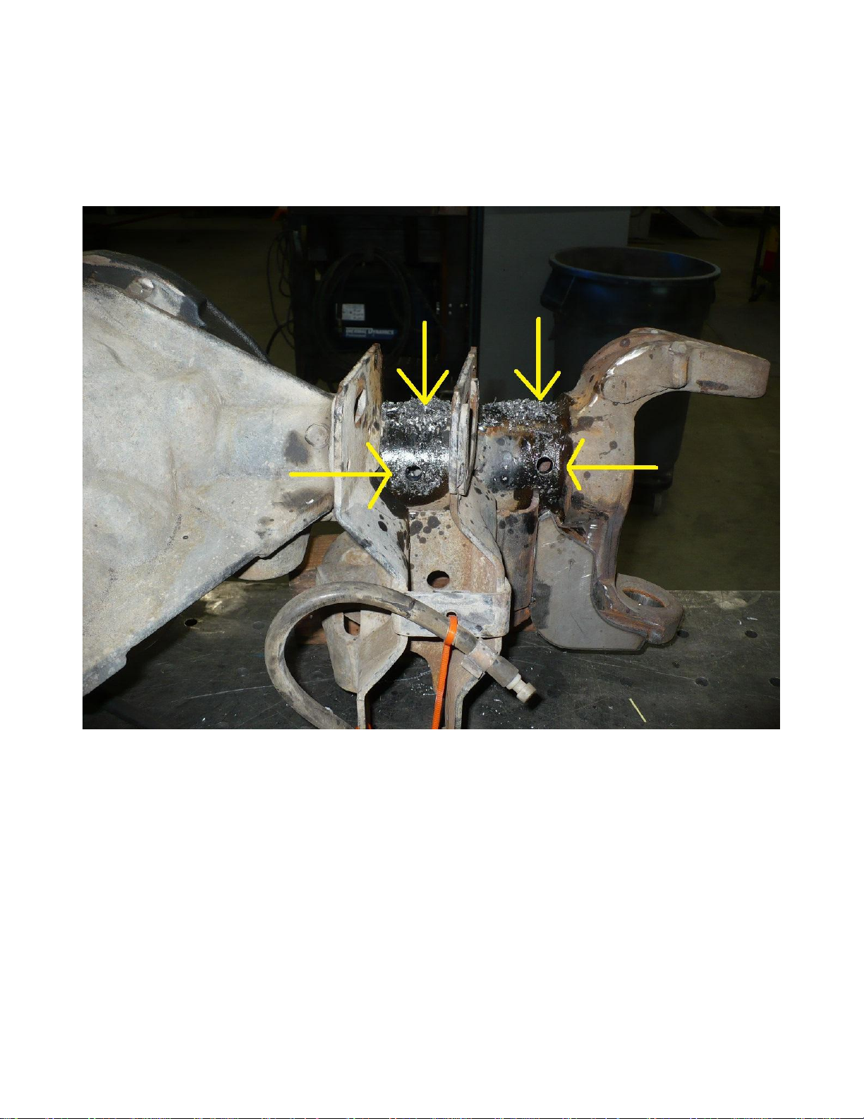
9) On the short side of the axle housing; Drill holes as shown in Figure 1&2 below. Drill 2 holes on the
front side, back side and bottom side of the tube axle tube. The factory coil and control arm bracketry
prohibits drilling and welding on the top side of the axle tube.
Figure 1
Page 3
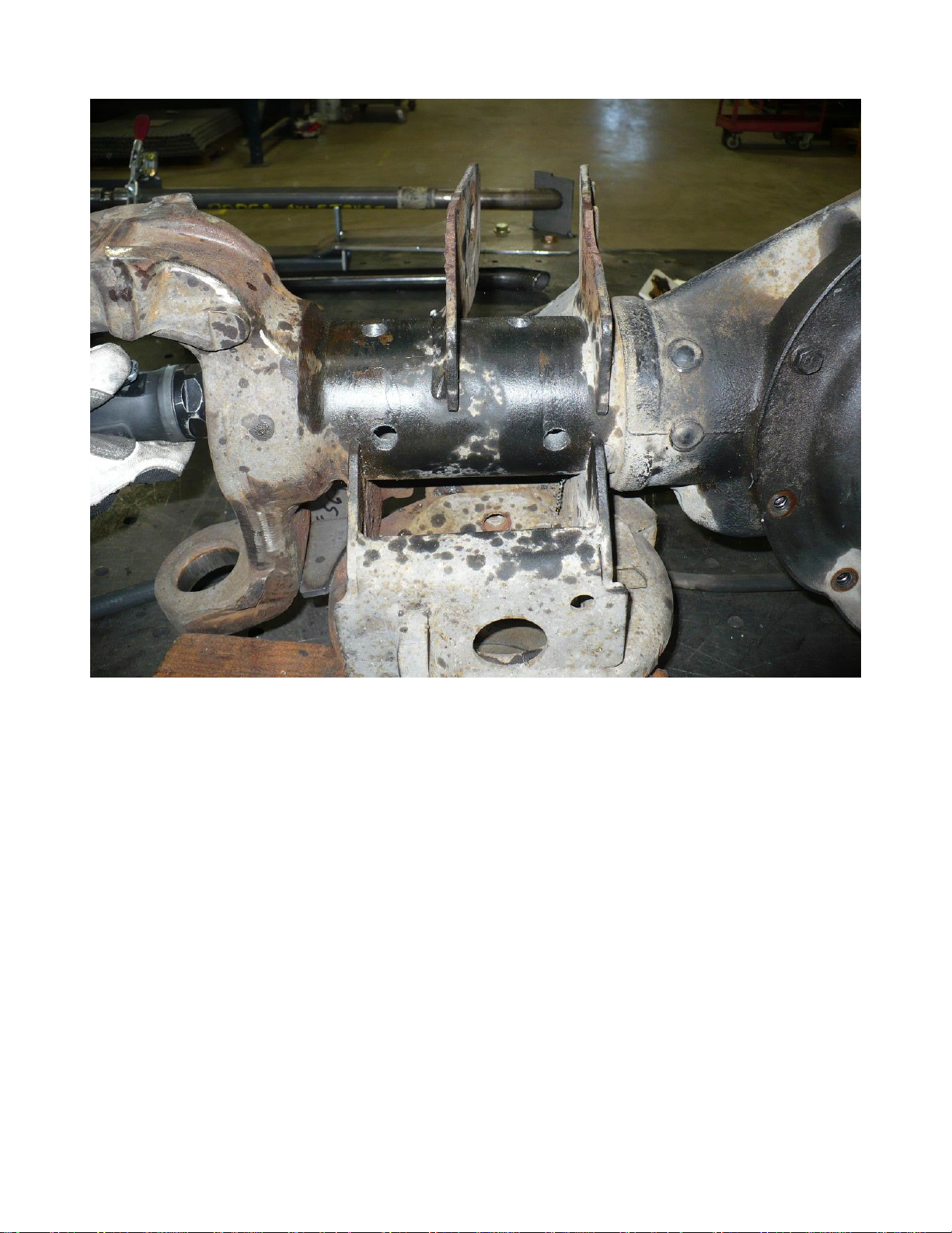
Figure 2
10) There should be a total of 6 holes on the short side of the housing.
11) Now mark and drill the holes needed for the long side of the housing.
Page 4

Page 5

12) Repeat the hole pattern for the top / front side of the housing where possible. There should be a total of
12 hole locations.
13) Center punch all hole locations and drill with a ½” drill bit.
14) Remove all paint around the hole surfaces.
15) Remove all metal shavings from both sides of the axle housing after drilling and grinding. A
telescoping magnet or long rod with a radius tab welded at 90 degrees can be used to scoop out the
shavings.
16) When all metal shavings are removed, slide in the new inner axle sleeves until they are flush with the
end of the stock tube. (Note, 2010+ models will slide in approximately 3/16” past flush with the end of
the axle tube. See image below.
17) Remove paint as needed from the axle C to allow for a clean weld on the end of the axle tube.
18) It is helpful to chamfer the edge of the axle sleeve as shown below to allow for a good weld joint.
Page 6

19) Once all weld areas are prepped and the installer is satisfied with the fitment, slide the axle sleeves into
place and tack on end as shown.
Page 7

20) Once weld areas are prepped, begin welding all plug welds. When complete, grind down plug welds
smooth with the axle tube.
21) Lastly, finish weld around the stock axle tube to the new inner sleeve as shown below.
22) Deburr welds and repaint the axle with quality paint.
23) Reassemble and install axle into the truck. Torque all suspension bolts with the vehicle sitting on flat
ground with the tires on. Torque the following items:
Unit Bearing Bolts – 149 ft-lbs
ABS Sensor - 34-50 in-lbs
Axle Nut – 132 ft-lbs, rotate axle shaft 5-10 times to seat the hub bearing, final torque to
263 ft-lbs
Brake Caliper Brackets – 130 ft-lbs
Driveshaft Bolts – 80 ft-lbs
Track Bar Bolts - (14mm (9/16”) – 125 ft-lbs 16mm (5/8”) – 145 ft-lbs)
Lower Control Arm Bolts - (14mm (9/16”) – 125 ft-lbs 16mm (5/8”) – 145 ft-lbs
18mm (3/4”) – 200 ft-lbs.)
Upper Control Arm Bolts – 125 ft-lbs
Drag Link & Tie rod Nuts - 80 ft-lbs
Sway Bar Nuts (stock) – 35 ft-lbs
Installation is Complete
 Loading...