

Page 1

SYNERGY MFG. 870 INDUSTRIAL WAY, SAN LUIS OBISPO, CA (805) 242-0397
8259-02 XJ SWAY BAR LINK KIT – FRAME SIDE DISCONNECT
BRACKETS
GENERAL NOTES:
These instructions are also available on our website; www.synergymfg.com. Check the website before
you begin for any updated instructions and additional photos for your reference.
NOTE – This kit is designed to be used in conjunction with 8259 XJ Front Sway Bar Link Kit.
PARTS LIST:
8259–02 XJ SWAY BAR LINK FRAME MOUNT BRACKETS
(2) 8259-02 Front Sway Bar Link Frame Disconnect Bracket
(3) 7/16-14 x 1.0” long hex head bolt
(1) 7/16-14 x 1.5” long hex head bolt
(8) 7/16” flat washer
(4) 7/16-14 nylock nut
(2) 807701 Sway Bar Disconnect Stud
(2) ½” Gr8 Flat Washer
(2) ½-20 UNF Stover Nut
Parts / Tools Needed to complete installation:
Basic simple hand tools.
Anti-seize, chassis grease
4-1/2” angle grinder or 3” air sander for slight material removal.
Quality drill and 7/16” metal cutting drill bit.
INSTALLATION:
1) Installation can be done with the vehicle sitting on the ground, under its own weight.
2) First, prepare the disconnect brackets for installation. Install the disconnect pins onto the bracket as
shown. Use a washer under the nut and orient the stud as shown on the bracket below.
Page 2
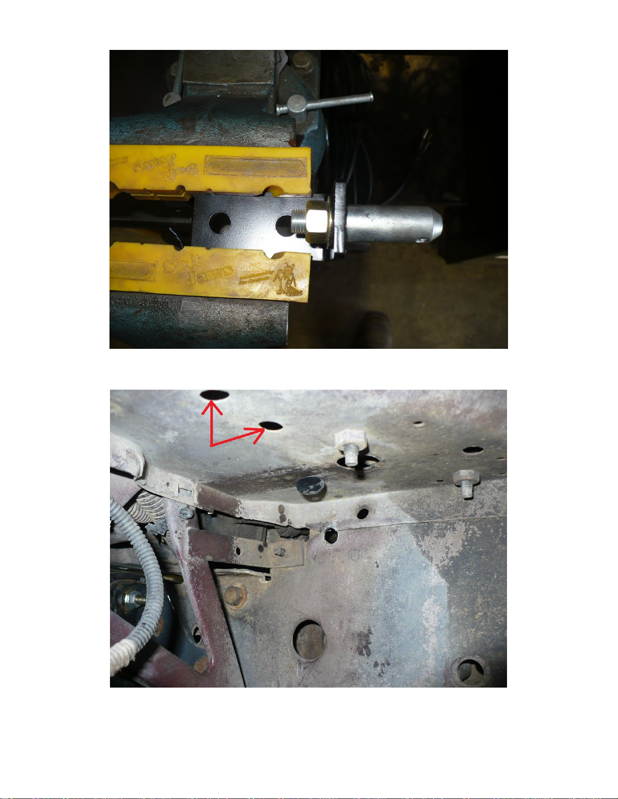
3) We will begin on the driver side. There are 2 factory holes which we will use for installation on the
driver’s side. Located in the fender well, nearly directly underneath the factory air box. The holes can
be seen in image 2.1 and 2.2 below.
Image 2.1
Page 3
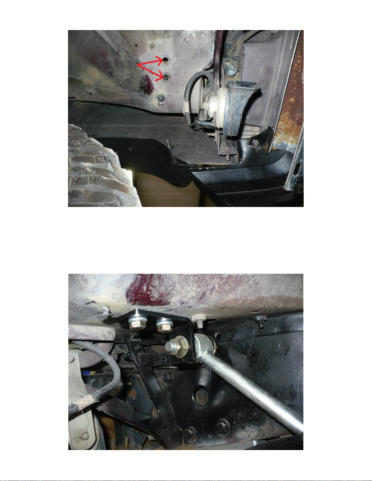
Image 2.2
4) After locating the 2 holes to be used for installation, open them up slightly with a 7/16” drill bit. Be
careful not to drill into any electrical components under the hood or into the air box.
5) Once holes have been clearanced, install the bracket as shown. Use 2 of the 7/16-14 x 1” long bolts and
install with a washer under both the bolt head and nut as shown. Torque bolts to 35 ft-lbs. Installation
is complete on the driver’s side.
Test that disconnect operates smoothly and lynch pin can easily be removed / installed.
Note, a small amount of grease on the stud is helpful for the first few uses.
Page 4

6) For the passenger side, start by removing the battery and battery tray. Passenger inner fender well
should appear as pictured below.
7) Next, knock out the stud furthest from the motor. A small hammer and a couple taps should remove the
stud.
Page 5

8) With stud removed, open up hole to 7/16”
9) Once removed, measure 3” back from the core support where it bulges out for the headlight bucket and
1.5” over towards the fender. See pictures 5.1-5.3 below for reference.
Page 6

Img. 5.1
10) Or, use the bracket as a template for the second hole location.
Page 7

11) Center punch and drill the hole using a 7/16” drill bit. Now is a good time to also open up the battery
tray using the 7/16” drill bit.
12) Note, on some models there will be a small ridge that needs to be sanded down in order for the bracket
to be installed. Sand down the ridge as shown to install the bracket.
Page 8

13) Touch up any bare areas of metal with paint before proceeding.
14) Install the bracket as shown. Use the 7/16-14 x 1.5” long bolt on the inner hole which goes through the
battery tray. Use a washer under both the head of the bolt and nut. Simply snug inner bolt which goes
through the battery tray as to not crack the plastic tray. Outer bolt can be torqued to 35 ft-lbs.
Page 9

15) Again, check that disconnect can be operated smoothly and that the lynch pin can be easily removed /
installed. A small amount of grease is useful for the first few uses.
Installation is Complete
 Loading...