

Page 1

SYNERGY MFG. 870 INDUSTRIAL WAY, SAN LUIS OBISPO, CA (805) 242-0397
INSTALLATION INSTRUCTIONS
SYNERGY MANUFACTURING
PPM-8095 RHD JK FRONT TRACK BAR BRACE /
SECTOR SHAFT BRACE
**DISCLAIMER** The Synergy Manufacturing 8095 system is designed around a stock
track bar. We cannot guarantee compliance with any other manufacturer’s track bar other
than the stock one and our own 8087 track bar.
-No bump stop spacers are required if using a stock track bar or the Synergy 8087 Track
Bar.
GENERAL NOTES:
• These instructions are also available on our website at www.synergymfg.com.
Check the website for any updated instructions and additional photos for
reference.
• Bracket is designed to be bolted on but can be welded on as well if desired.
• The installation of this kit can be done with simple hand tools with the vehicle
sitting on the ground under its own weight. However, it is easier to install with
the front suspension drooped out.
• Proper bump stop spacers are strongly recommended to prevent damage from
possible track bar / steering box contact.
• Steps 1-10 covers the installation of the 8095-01 Track Bar Brace. Installation is
complete after step 10 if 8095-02 Sector Shaft Brace is not being installed.
• Steps 11-22 covers the installation of the 8095-02 Sector Shaft Brace. 8095-02
cannot be installed without the 8095-01 Track Bar Brace. It is a modular system
which works together to strengthen the driver’s side track bar / steering box
mounting locations.
PARTS LIST:
8095-01
• 1 - PPM-8095 RHD JK Front Track Bar Brace
• 1 - 9/16-12 UNC x 3.25” long track bar bolt
• 1 – 9/16-12 UNC top lock nut
• 2 - 7/16-14 UNC 1” bolts
• 4 - 7/16 flat washers
• 2 - 7/16-14 UNC top lock nuts
Page 2
• 1 – M14-2.0 x 80mm long track bar bolt
• 1 – M14-2.0 top lock nut
**Note** 2012 and up models retaining the stock track bar, must use the metric 14mm
hardware provided
8095-02
• 1 – PPM-8095-02 RHD Sector Shaft Brace (Needle Bearing and grease zerk
installed)
• 1 – Pitman Arm Stud
• 1 – 7/16-14 UNC x 3/4” long bolt
• 2 – 7/16-14 UNC top lock nuts
• 2 – 7/16-14 UNC x 1” long flat head socket cap screws
• 3 – 7/16” flat washers
INSTRUCTIONS:
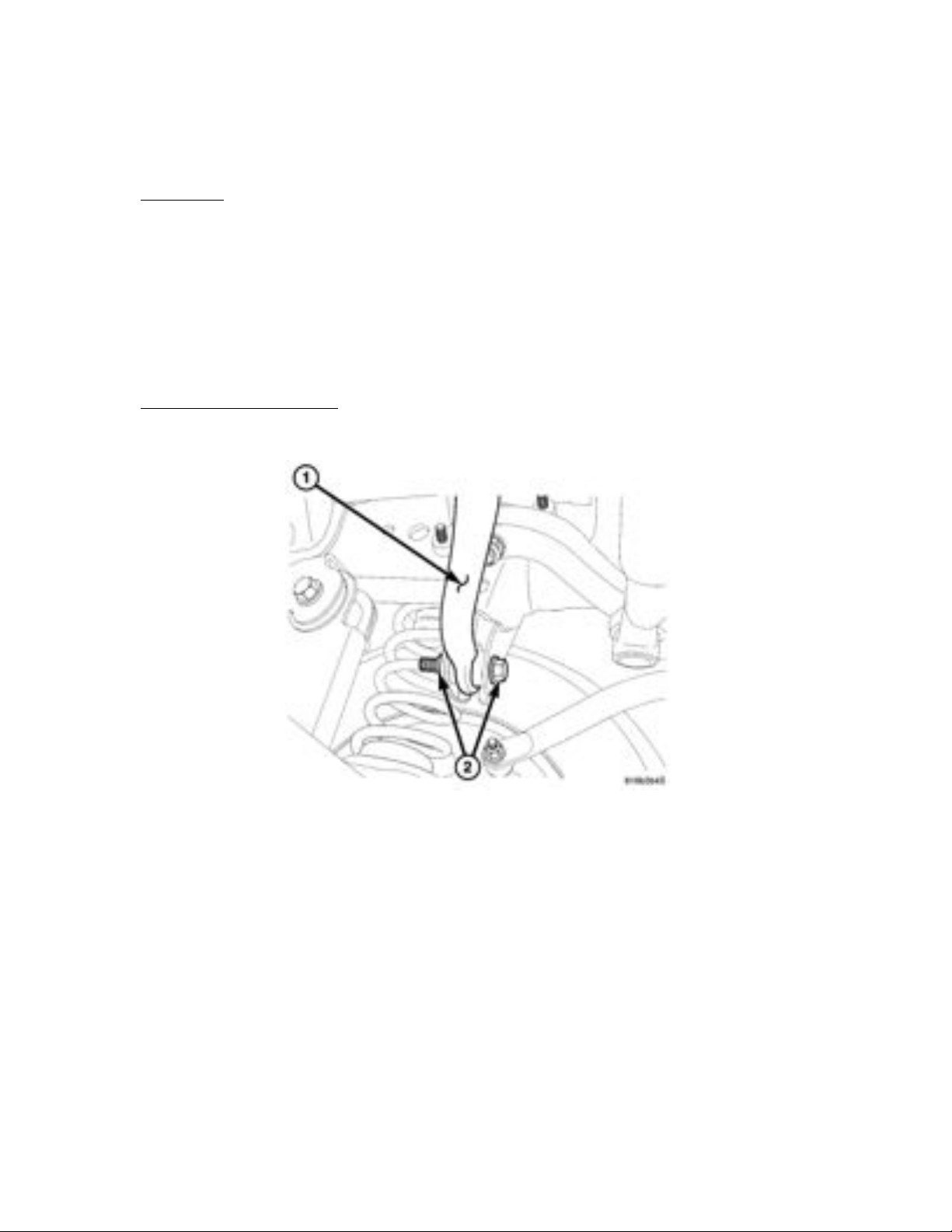
1) Remove the nut and bolt (2) from the TB bracket.
2) After removing the TB bolt from the frame, raise and support the vehicle using
jack stands so the axle can swing freely. Having the suspension at droop makes
installation much easier. Remove the driver front tire.
Page 3
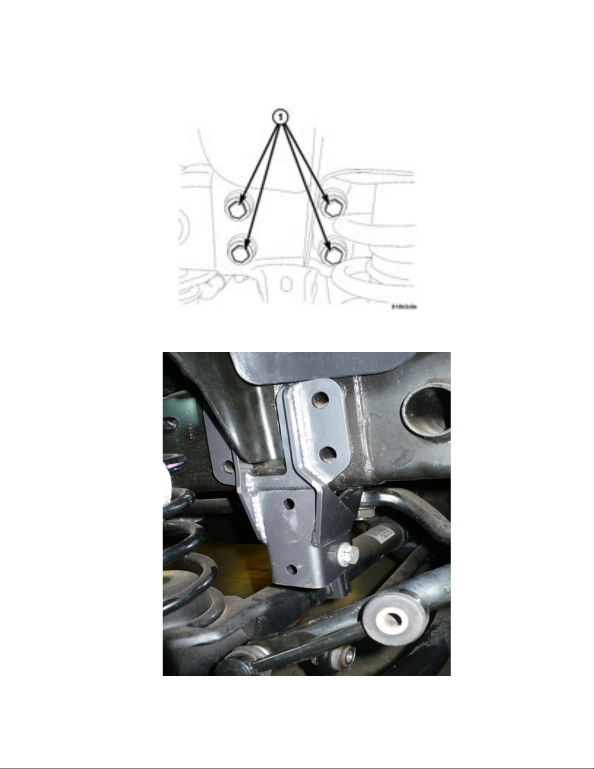
3) Next, remove the 4 steering box bolts shown (1)
o Note – reach under the steering box and support it as the last bolt is
removed. Rest the steering box on the top of the frame.
4) Next, install the PPM-8095 Track Bar Brace by fitting it over the factory track bar
mount and installing the TB bolt removed in step 1. Install the nut on the
backside and tighten the bolt finger tight.
Page 4
5) Next, align the holes in the steering box with the holes on the bracket and the
holes on the frame. Then, loosely install all 4 steering box bolts removed in step
o Note – apply a small amount of blue locktite to the threads of the steering
box bolts
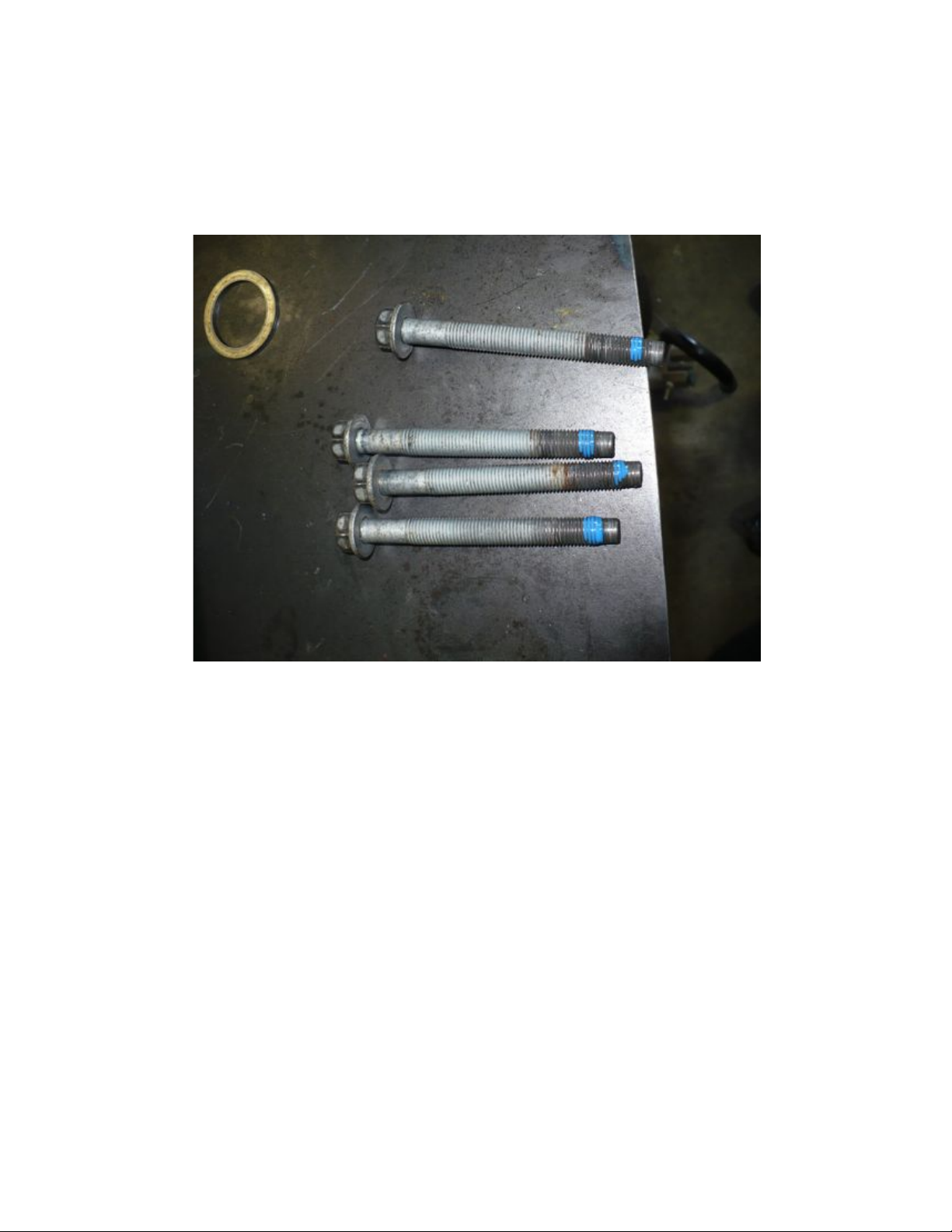
6) Next, install the 1” long 7/16-14 UNC bolts provided in the kit as pictured below.
Use a flat washer under both the head of the bolt and under the stover nut. Orient
bolt as shown with the nut on the outside of the bracket.
Page 5

7) Fully tighten bolts. Torque steering box bolts to 70 ft/lbs.
8) Torque the 7/16” bolts installed in step 6 to 70 ft-lbs.
9) Remove the stock TB bolt, reinstall front drivers side tire and lower vehicle onto
the ground.
o Align Track Bar and install the new 3.25” long 9/16-12UNC bolt provided
in the kit. Use a flat washer under both the head of the bolt and the stover
nut.
Page 6

10) Lastly, torque the 9/16-18 UNF track bar bolt (1) to 125 ft-lbs (**NOTE** Skip
this step if installing 8095-02 Sector Shaft Brace as well, this will be mentioned
again in Step 18)
11) The remainder of the steps in these instructions will cover the installation of the
8095-02 RHD JK Sector Shaft brace
o Begin by removing the pitman arm nut (#3 in image below)
12) With pitman arm nut removed, install the sector shaft brace as shown below.
Take note, you will be reusing the factory lock washer. Slide the new pitman arm
stud into the bearing housing as shown. (Hex on bottom)
o NOTE – We suggest putting a dab of anti-seize on the threads of the sector
shaft to prevent galling / seizing at a later time. This will also help
provide more accurate torque measurements.
Page 7

13) Next, slide the whole assembly into place over the 8095-01 Track Bar Brace and
start the pitman arm stud. Tighten finger tight.
Page 8

14) Next, align the outer bolt holes so the 7/16-14 x 1.0” long bolts provided in the kit
can be installed. An alignment bar or screw driver will aide in pulling mount into
proper location.
15) With holes aligned, install the 7/16-14 x 1.0” long flat head socket cap screws
provided in the kit. Use a washer under the head of the nut. Orient hardware as
shown. Do not tighten at this time.
16) Now, install the 7/16-20 UNF x ¾” long bolt into the bracket as shown. Note that
the bracket is threaded and the bolt must be installed from the inside of the factory
track bar mount as shown below. Be sure to use a washer under the head of the
bolt.
Page 9

17) With all hardware started, torque in the following order to the corresponding
torque specifications:
o Pitman Arm Stud - 150 ft-lbs.
o 7/16-14 bolts - 50 ft-lbs (NOTE – We are aware it is difficult to get a
torque wrench on some of these bolts so simply tighten snug using a
standard 6-8” long combo wrench.)
18) With all hardware torqued, it is a good idea at this time to check for adequate
track bar clearance. If running a stock track bar or Synergy 8087 track bar, there
should be no clearance issues. However, if running a different aftermarket track
bar, follow these steps to check for adequate clearance.
o Install the track bar to be used at the frame side and lift the opposing side
as high as possible until contact is made with the frame or with the pitman
arm stud.
o If contact is made with the pitman arm stud well before contact with the
frame, take note of the amount of space between the frame and mounting
hole on the axle end of the track bar. This is the minimum bump stop
requirement needed for the track bar, if using stock mounting point on the
axle.
o If there is any doubt, we advise hooking up the track bar at both ends and
fully bottom out the suspension.
Page 10

Stock track bar unbolted from axle and raised to the frame to simulate full bump
conditions.
Note - adequate clearance is available between the track bar and bottom of the pitman
arm nut.
Page 11

19) Once adequate clearance has been determined and proper bump stop spacing has
been addressed, fully install the track bar using the 9/16-12 UNC x 3.25” long TB
bolt provided in the 8095-01 kit.
o Be sure to use a washer under both the head of the bolt and under the
washer. Torque bolt to 125 ft-lbs
o Reattach track bar at axle side, follow the mfr’s specifications for torque
specs.
1) Synergy Manufacturing’s 8087 track bar and stock track bar retain
the OEM bolt and is to be torque to 125 ft-lbs.
20) Lastly, grease the bearing in the sector shaft brace using quality chassis grease. 1-
2 pumps is plenty. Re-grease at normal chassis lube intervals or after any severe
mud or deep water fording.
21) Recheck torque specs after the first 100 miles of driving.
22) Installation is complete.
 Loading...