

Page 1

SYNERGY MFG. 870 INDUSTRIAL WAY, SAN LUIS OBISPO, CA (805) 242-0397
8021 / 8041 JEEP JK SYNERGY STAGE 1 SUSPENSION SYSTEM
GENERAL NOTES:
• These instructions are also available on our website; www.synergymfg.com. Check the
website before you begin for any updated instructions and additional photos for your
reference.
• The installation of this suspension kit requires drilling a 3/8” hole on the front
axle coil buckets.
• Installation requires trimming of the rear track bar bracket and shock brackets with
either a grinder with a cut off wheel or sawz-all.
• You will need basic hand tools, a drill with 3/8” drill bit; a grinder with cut off wheel or
sawz-all, floor jack or automobile lift, and two sturdy jack stands to complete this
installation.
• A list of additional components that can be added to this kit are available on our
website. These components can be purchased and installed at a later date. Each
component has instructions for installation.
• For Non-Rubicon models, we recommend installation of 8077 JK Front
Sway Bar Quick Disconnect Kit for removal of the front sway bar links to increase
suspension articulation while off road.
• The longer rear sway bar links may be close to or rub the inside of the rear tires.
Wheels will less back spacing (4.5” max) or wheel spacers can be used.
• We recommend that you upgrade to conventional double cardon CV style drive shafts
during or soon after the suspension installation. The large diameter front drive shaft may
rub on the automatic transmission pan and the CV boots will tear prematurely due to the
increased operating angle caused by the suspension lift, especially 2 door rear drive shafts
and 2 or 4 door front drive shafts.
1. Unpack the suspension components from boxes; verify that all parts have arrived,
intact and in good condition.
Synergy Stage 1 Parts List
8004 - JK 9/16" Control Arm Cam Bolt Kit
8063XX - JK Front Lift Springs
8064XX - JK Rear Lift Springs
80XX - JK Front Bump Stop Spacer Kit
80XX - JK Rear Bump Stop Spacer Kit
8061 - JK Front Track Bar
8056 - JK Rear Track Bar Bracket
8083 - JK Front Brake Line Relocation Kit
8084 - JK Rear Brake Line Relocation Kit
8060 - JK Rear Sway Bar Links
Page 2

2. Read all the following steps before beginning installation. If you do not have the
proper tools or ability to install the components properly do not attempt installation.
Find a creditable, local shop to do the installation work.
FRONT SUSPENSION
3. REMOVE STOCK PARTS
• Remove the front track bar. It is easiest to do this when the suspension is at the ride
height position.
• Remove the automatic transmission skid plate if equipped to prevent damage to the
front drive shaft when the suspension is drooped out.
• Remove the rear sway bar links, these will be reinstalled on the front sway bar.
• Use a floor jack under the center of front axle to lift the tires off the ground. Place jack
stands under each frame rail just behind the lower control arm mounts to support the
weight of the Jeep. Raise or lower the floor jack under the front axle to remove and
install suspension components. The jack should stay under the axle the entire time the
front suspension is being installed.
• Now remove these suspension components and retain the hardware in this order:
• Front Wheel/Tires
• Loosen the upper control arm bolts and lower control arm frame mount bolts
• Sway bar links
• Shocks
• Remove the brake line frame bracket bolts, but do not open the hydraulics
• Lower the axle and remove the springs, make sure the wheel speed sensors wires
are not overextended, loosen any retaining clips if needed to allow enough slack.
4. BRAKE EXTENTIONS
● Find the correct front brake line brackets, the front brackets are the shorter
ones, and there is a left and a right. Install the new extension bracket to the frame
with the stock bolt.
● Bolt the brake line to the extension bracket using the new supplied hardware.
You will need to straighten the brake hard line with your hands to give enough
slack for the brake line to reach the extension bracket.
5. FRONT LOWER CONTROL ARM CAM BOLTS
* Cam bolts are necessary if you choose to retain the stock lower control arms. If you do
not want to perform the following procedure you can purchase adjustable lower control
arms. 8051 Synergy Adjustable Front Lower Control Arms
• Remove the lower control arm bolts at the axle housing. Let the control arms drop out
of the control arm mount.
Page 3
• Remove the cam positioning tabs from the LCA mounts. You can purchase 8004-01 JK
Cam Bolt Knockout Tool or if you have the proper tools you can cut the tabs out.
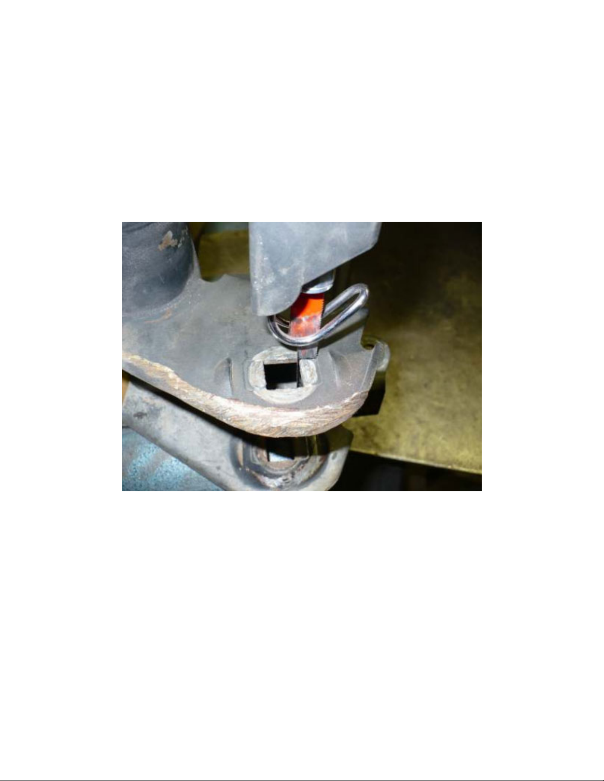
• You will notice that the bolt hole in the LCA mount is square. There are partially
punched metal tabs at the front and back of the square hole; these tabs need to be
punched out to make the LCA mount slotted. Since you need to increase castor, only the
tabs that are toward the rear of the vehicle need to be punched out. The easiest way to
remove the tabs is to cut the top and bottom with a narrow saw blade (Figures
5-1 and 5-2), then bend/break the tabs out with pliers (Figure 5-3). You may need to
clean the burr from the back edge of the hole with a file or carbide burr for the cam
bolt/washer to fit (Figure 5-4). Do this to each side of both front LCA mounts. Total of
four places.
Figure 5-1
Page 4
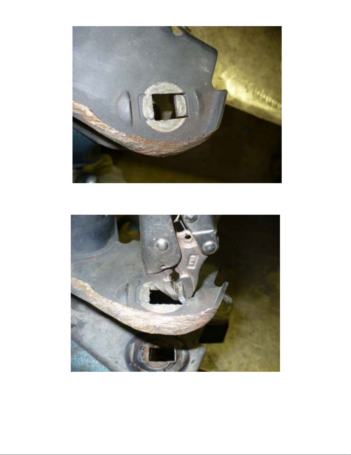
Figure 5-2
Figure 5-3
Page 5

Figure 5-4
• Reinstall the lower control arms using the new cam bolts. Use anti-seize liberally on
the cam bolts and washers. Position the cam bolts to maximize caster (bolt positioned to
the rear most portion of the vehicle, Figure 5-5). Final caster can be set when the vehicle
is aligned by a professional shop after installation, but most likely you can just adjust to
the max castor.
Figure 5-5
Page 6

• Wait to torque the new cam bolt until the vehicle is on the ground.
6. BUMPSTOP SPACERS AND COIL SPRINGS
• Locate and center punch the center of the bump stops strike pad on the axle coil spring
mounts. Drill a 3/8” hole.
Figure 6-1
• Put the bump stop bolt though the bump stop and slide the bump stop into the bottom of
the coil spring.
• Install the coil spring while holding the bump stop spacer inside the coil spring.
When the spring is in place, align the bump stop spacer bolt with the hole that was
drilled. Install the bump stop bolt through the hole and the 3/8” serrated nut onto the
bump stop bolt. Hand tighten the nut and then use a 5/16” allen wrench through the coil
spring to tighten the bump stop bolt.
Page 7

7. SHOCKS
• Install the shocks using the stock lower mounting nut/bolt. Use the new stem bushings,
washers and nuts.
• Tighten the lower bolts to 56 ft-lbs
• Install the thicker of the two upper stem bushing nuts and tighten until the bushing
begins to bulge out. Install and tighten the jam nut.
8. SWAY BAR LINKS
• Install the rear sway bar links to the sway bar and axle tabs. The sway bar links go on
the outside of the sway bar and inside of the tabs just like the original front ones were
mounted.
• Torque the upper sway bar nut/bolts to 75 ft-lbs. Wait to tighten the lower bushing
nut/bolt when the jeep is sitting at ride height.
9. FRONT TRACK BAR
• Install the front track bar with the bushing at the frame end and rod end at the axle end.
Attach the track bar to the frame bracket only, you will need to wait until the tires and
wheels are installed and the jeep is sitting on the springs with the tires on the ground to
attach the axle end.
• The rod end can be adjusted by turning the adjuster sleeve with a ¼” punch or similar
tool. Wait to adjust the track bar until the tires are on and the vehicle is on the ground at
ride height.
10. INSTALL TIRES AND WHEELS AND REMOVE FROM JACKSTANDS
• Raise the front axle with the floor jack and install the tires and wheels.
• Remove the jack stands supporting the frame and lower the axle so wheels are back on
the ground
• Attach the track bar to the axle bracket using the original bolt. Make sure the two
spacers are installed in the rod end. Use the factory bolt and nut tab. You can have a
helper turn the steering wheel to alight the track bar bolt. Wait to torque the track bar
bolts until the end of the suspension installation.
• Reinstall the automatic transmission skid plate if equipped.
• The installation of the front suspension is complete except for the steering wheel
alignment and final torque of the control arm bolts, sway bar links and track bar. You
may want to wait until the rear is finished because you will be using similar tools and
torque settings.
Page 8

REAR SUSPENSION
11. REMOVE STOCK PARTS
• Disconnect the rear track bar at the axle bracket. It is easiest to do this when the
suspension is at the ride height position
• Use a floor jack under the center of axle to lift the tires off the ground. Place jack
stands under each frame rail just in front of the lower control arm brackets to support the
weight of the Jeep. Raise or lower the floor jack under the rear axle to remove and install
the suspension components. The jack should stay under the axle the entire time the rear
suspension is being installed.
• Now remove these suspension components and retain the hardware in this order
• Rear Wheel/Tires
• Loosen both the upper and lower control arm bolts
• Remove the shocks
• Remove the parking brake cable wire formed retainer from the floor
• Remove the brake line frame bracket bolts, but do not open the hydraulics
• Disconnect the parking brake cables at the axle end
• Lower the axle and remove the springs, make sure the wheel speed sensors
wires are not overextended, loosen any retaining clips if needed to allow
enough slack
12. INSTALL BRAKE EXTENTIONS
● Find the correct rear brake line brackets, the rear brackets are the longer ones, and
there is a left and a right. Install the new extension bracket to the frame with the stock
bolt.
● Bolt the brake line to the extension bracket using the new supplied hardware. You
will need to straighten the brake hard line with your hands to give enough slack for the
brake line to reach the extension bracket.
13. INSTALL BUMPSTOP SPACERS
• Install the new rear bump stop spacers. The bump stop spacers should be oriented so
they lean forward. See Figure 121. Use a washer under the head of the 3/8 bolts and use
the serrated nut on the bottom. Tighten to 30 ft-lbs.
Page 9

Figure 12-1
14. INSTALL REAR TRACK BAR RELOCATION BRACKET
• Cut part of the factory track bar off as shown in the following pictures. The
pictures are shown using a 4 ½” grinder with a cut off wheel, but a sawz-all can
also be used.
Page 10

• Attach the new track bar relocation bracket to the factory bracket as shown with the
new 9/16” bolt and lock nut; use a flat washer under the bolt head and lock nut.
• Install the u-bolts over the axle tube and through the track bar relocation bracket, use a
flat washer and nylock nut to secure the u-bolt.
• Torque the 9/16 bolt to 150 ft-lbs, and the 3/8” u-bolts to 30 ft-lbs
• Wait until the vehicle is sitting at ride height to attach the track bar.
15. INSTALL COIL SPRINGS AND SHOCKS
• Install the new coil springs.
• Jack the axle up enough to install shocks using the original hardware, torque the upper
bar pin bolts to 37 ft-lbs and the lower bolt and nut to 56 ft-lbs.
16. INSTALL REAR SWAY BAR LINKS
• Install the new sway bar end links; torque the lower bolt to 75 ft-lbs and the upper to 60
ft-lbs. If tire clearance is an issue, you can mount the sway bar links to the inside of the
sway bar and axle tab.
17. PARKING BRAKE CABLES
• 4DR MODELS: The parking brake cables are routed above the cross member that is in
front of the wire formed hanger you have previously removed. Re route the parking
brake cables to underneath this cross member and gas filler hose and secure to the cross
member with a zip tie. The wire formed hanger is no longer used.
• 2DR MODELS Re route the parking brake cables underneath the gas filler hose.
The wire formed hanger is no longer used
18. FINAL ASSEMBLY
• Jack the rear axle up enough to install the tires and wheels.
• Remove the jack stands from under the frame and lower the jeep to the ground.
• Attach the track bar to the new track bar relocation bracket using the factory nut and
bolt. If the track bar does not line up with the hole you can have someone push the back
of vehicle from side to side to align the track bar bushing to the hole in the bracket.
19. FASTENER TORQUE
• Now that the vehicle is sitting at ride height on level ground you can do the final
fastener torque
• Torque the front and rear lower control arm bolts to 125 ft-lbs
• Torque the rear upper control arm bolts to 125 ft-lbs
• Torque the front upper control arm bolts to 75 ft-lbs
• Torque the front and rear track bar bolts to 125 ft-lbs
• Torque the sway bar bolts to 75 ft-lbs
Page 11

• Torque the lug nuts to 85125 ft-lbs.
20. FRONT END ALIGNMENT
• The castor should be optimal with the cam bolts maxed for the most castor.
• Adjust the front track bar to center the front axle. Torque the pinch bolt to 30 ft-lbs
• Adjust the draglink to center the steering wheel by using the adjuster sleeve on the
driver side tie rod end (pitman arm end).
• If the steering wheel is not centered the ESP light will come on, so make sure you adjust
the draglink so the steering wheel is perfectly centered. This is can be done by test
driving and making the necessary adjustments. When driving in a straight line take note
of which way the steering wheel needs to turn to be centered. If the steering wheel needs
to turn right to be centered, shorten the draglink. If the steering wheel needs to turn left
to be centered, lengthen the draglink
• We recommend you have the jeep aligned by a professional alignment shop.
• Check all hardware after 500 miles of driving.
• We recommend checking all hardware before and after all off road trips to avoid failure
due to loose fasteners.
Please call you if you have any questions, we can be reached M-F 8-5 PST.
 Loading...