

Page 1

SYNERGY MFG. 870 INDUSTRIAL WAY, SAN LUIS OBISPO, CA (805) 242-0397
PPM-8009 JK DANA 44 HD FRONT AXLE GUSSET
KIT
Version 1.0
GENERAL NOTES:
• These instructions are also available on our website; www.synergymfg.com.
Check the website before you begin for any updated instructions and additional
photos for your reference.
• Please read these instructions carefully before you start, do not attempt if you do
not have the tools or skills required.
• This kit only works on a factory JK front Dana 44 axle housing
• This kit requires you to cut off all the factory axle brackets, careful cutting,
measuring and welding is involved, do not attempt if you do not have the skills to
properly perform this operation
• You will need a welder, cutting torch or plasma cutter, grinder, tape measure and
some sort of level or angle finder.
• For best results when welding to the cast diff housing, we recommend TIG
welding with stainless 312 rod or similar rod that is meant for cast iron welding to
mild steel. MIG and stick welding is also possible with the right rod, pre and post
heat.
1. Unpack all of the components and verify all the parts are there and are in good
condition. These are the parts that are included
• 8009-00 Short and long outer axle sleeves
• 8009-01 Track bar bracket and sway bar tab
• 8009-02 Lower control arm brackets (pair LH & RH)
• 8009-03 Lower shock mount brackets (pair LH & RH)
Optional parts
• 8009-07 Inner C gussets, 2 sets (4 pcs total)
• 8009-09 Axle truss
• 8009-10 Hydro assist ram bracket
2. Remove axle housing from the vehicle, you do not have to remove the gears &
locker, axle shafts or knuckles.
3. Using a plasma cutter or oxy-acetylene torch, cut off all of the suspension brackets
from the axle tubes, refer to the following steps for specific instructions.
4. Cut off the sway bar tabs and coil spring mounts on both sides. The coil spring
mounts will be re-used so try to just cut along the top edge of the weld bead on the
Page 2
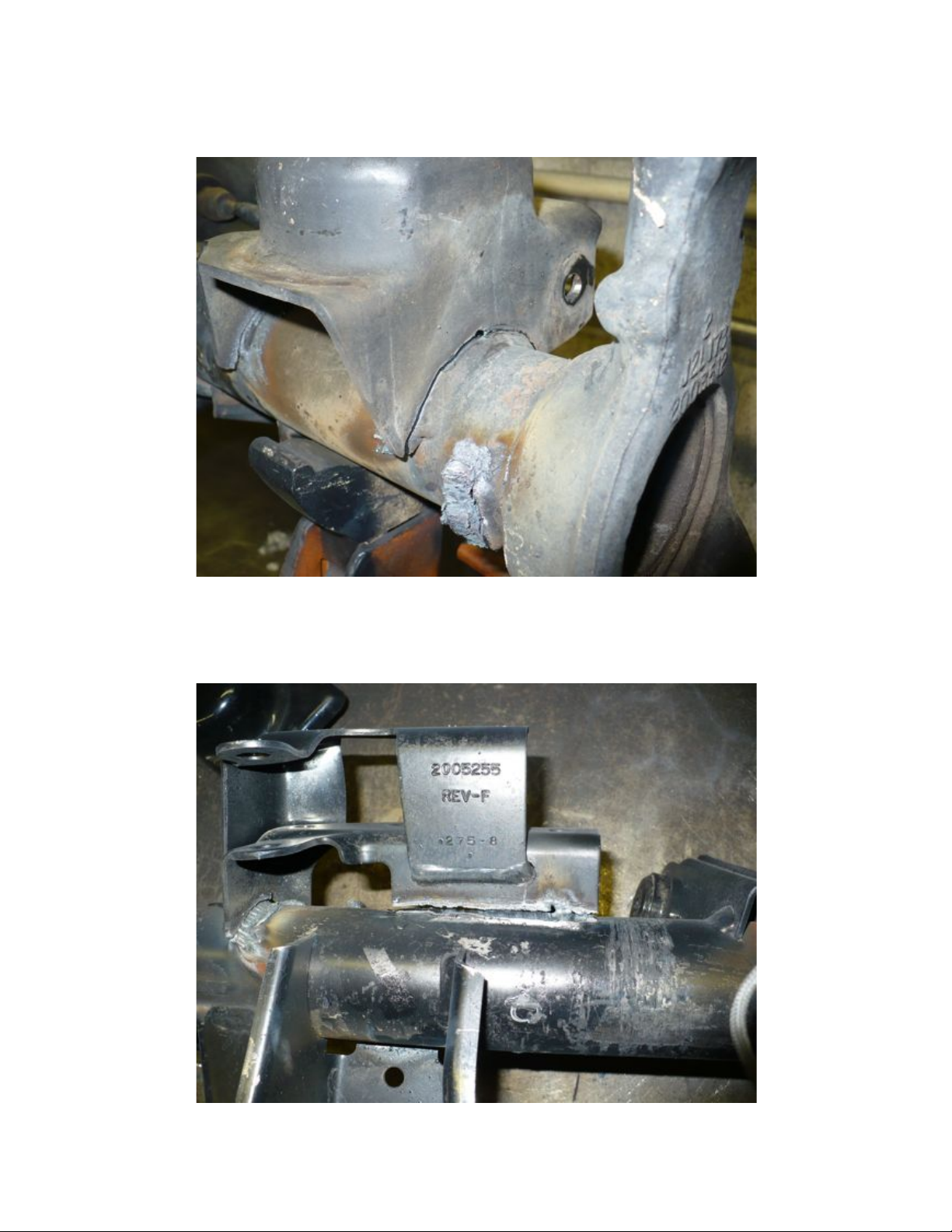
side of the coil mount. This will compensate for the 1/4” thick shell that will go
under it. Tag the left and right so you can put them back on the side they were
removed from. The sway bar tabs will not be reused.
5. Cut off the track bar bracket, this will not be reused so try to cut most of the weld
bead off the tube so you will have less to grind.
Page 3
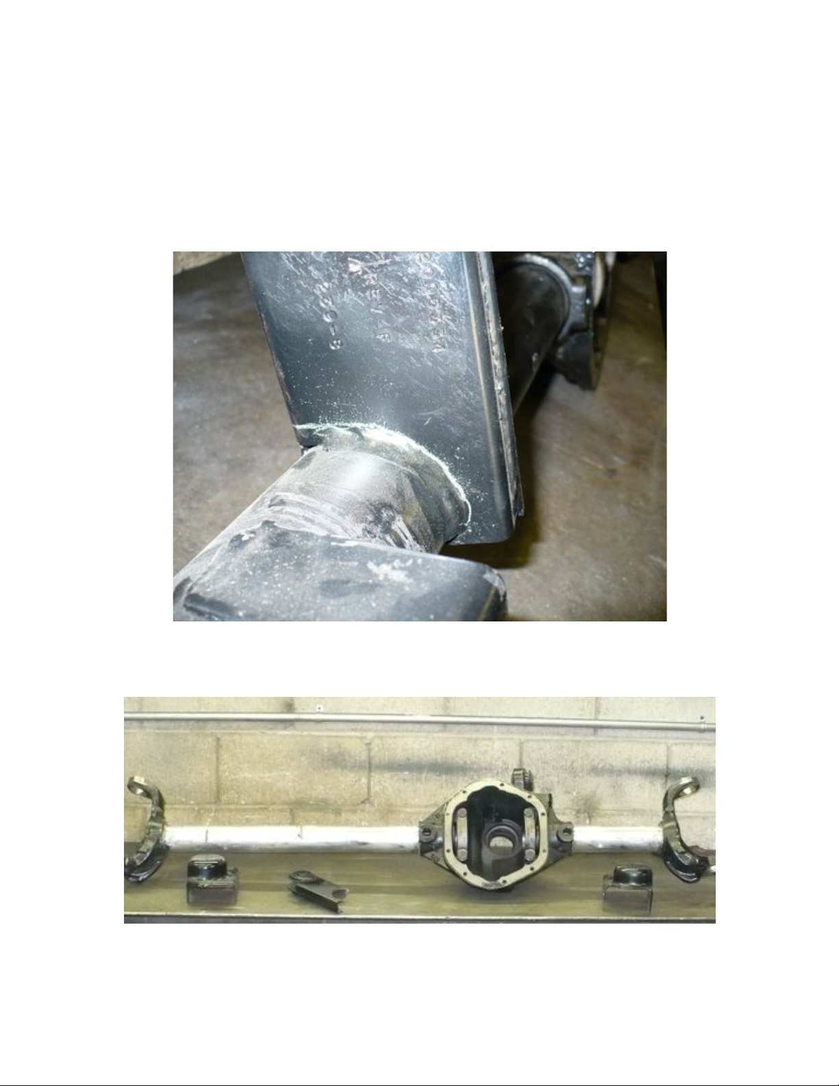
6. Cut off the lower control arm brackets and shock mounts. These will not be
reused so try to cut most of the weld bead off the tube so you will have less to grind
off.
7. Cut off the upper control arm bracket. The upper control arm bracket will be reused so try to just cut along the top edge of the weld bead on the side of the upper
control arm bracket. This will compensate for the 1/4” thick shell that will go under
it.
8. Grind all the of weld smooth from the axle tube. It should look something like this
when you’re done, these are the parts you will need to reuse
Page 4
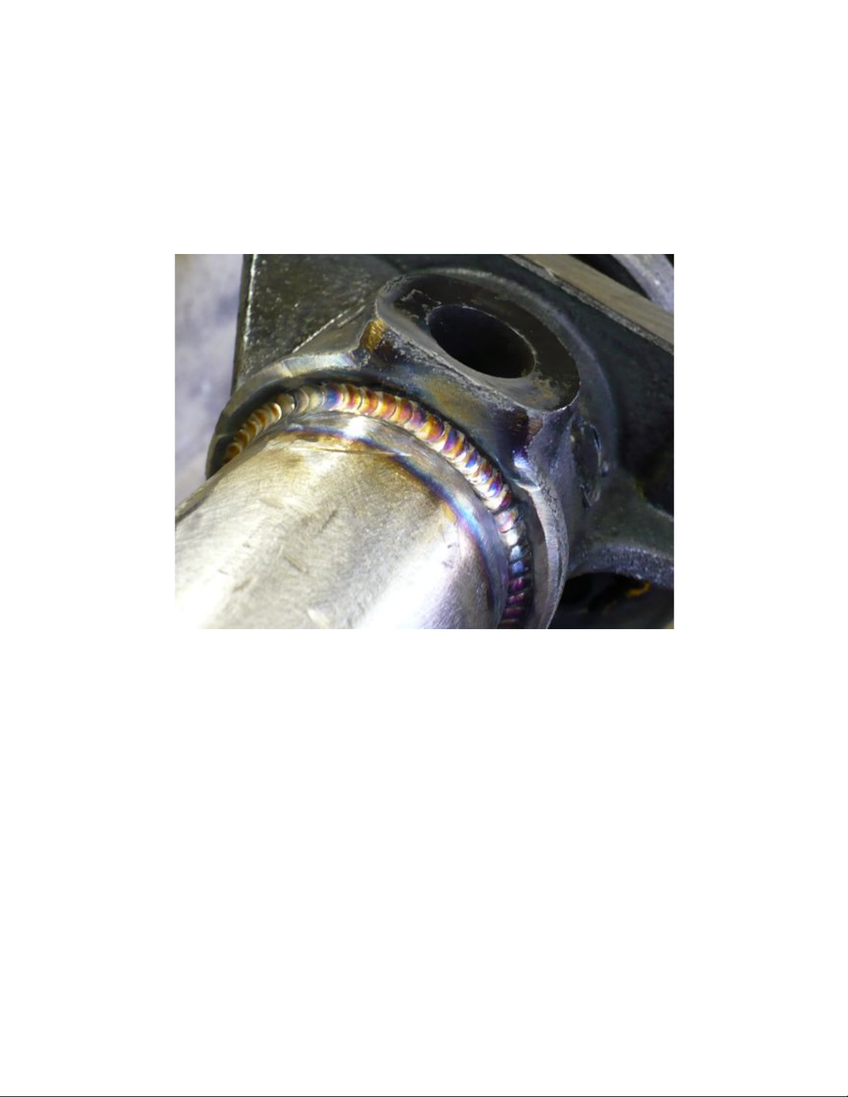
9. We recommend that you weld the axle tubes to the cast center section. Tig welding
with stainless 312 or similar dissimilar metal welding rod works best. You can also
mig or stick weld with pre and post heat.
Page 5
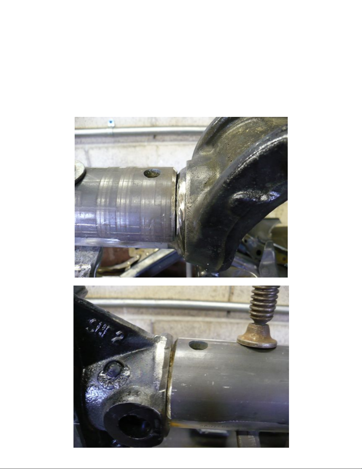
10. Prepare the outer tube shells by deburring the inside of the laser cut edge, make sure
there is no slag from the laser cut edge on the inside of the tube and the inside of the
holes. Grind a chamfer on the outside radial edges of both ends of the tube shells for
a V groove to weld the outer tube shell to the cast center and inner C. Grind a
chamfer for clearance of weld bead at the center section in step 9.
Page 6
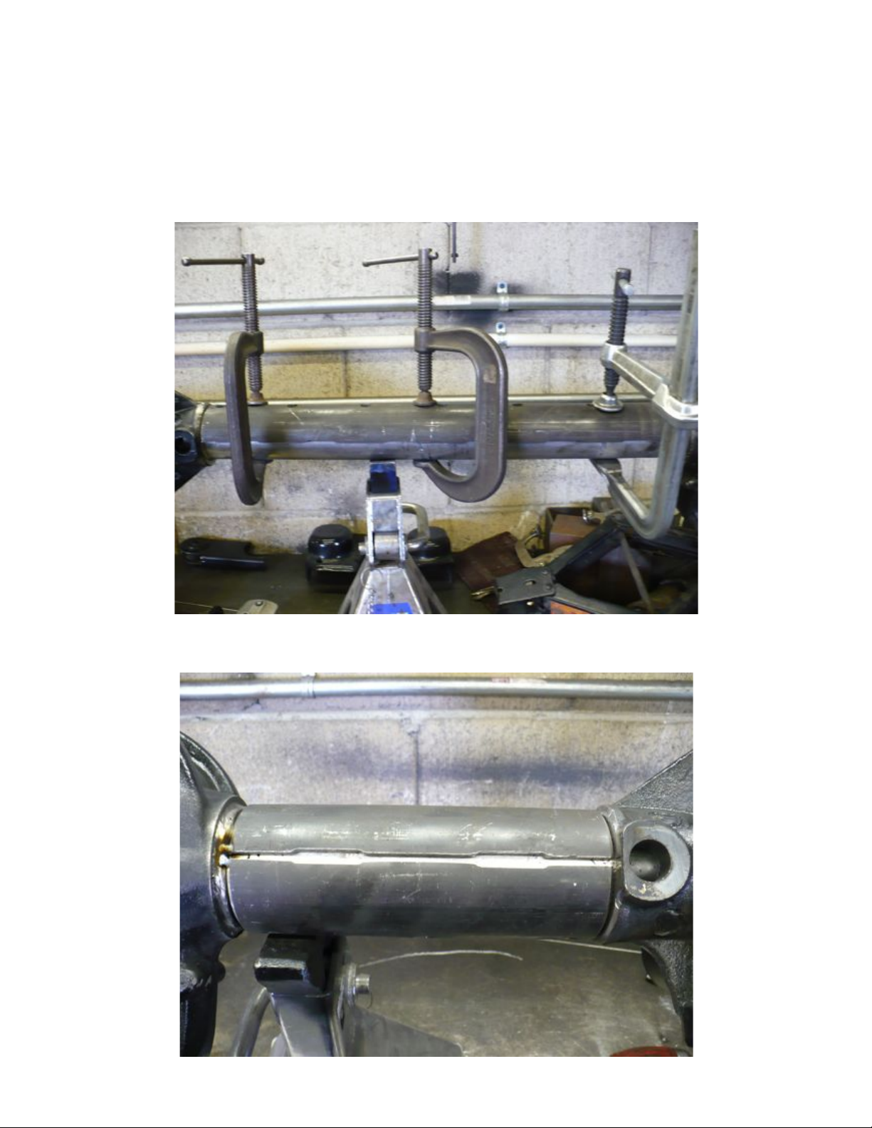
11. Position the outer tube shells to the axle tube. The holes should be oriented at the top
and bottom with the seam at the front and back. Do one at a time by clamping the
tube shell to the tube and tack welding it to the axle tube
Make sure the seam is even on the front and back
Page 7

12. Weld the seam between the two outer shell halves. The narrow seam is intended to
just weld the two shell halves to each other; the wide seam is intended to weld the
outer shell halves to the axle tube. Start at center and work your way out by welding
one section at a time (about 1 ½” of weld per section). Alternate welding the same
section front to back and side to side. Since you are welding on opposite side of the
tube it will not bend the axle tube.
13. Weld the holes on the top and bottom of the tube shell, try to weld the axle tube to the
shell and not just fill the hole.
Page 8

14. Weld the outer end of the tube to the inner C
15. Weld the inner end of the tube shell to the cast center section. Tig welding with
stainless 312 or similar dissimilar metal welding rod works best. You can also mig or
stick weld with pre and post heat.
Page 9

16. Place the axle on jack stands on level ground or on a flat work or welding bench.
Support the pinion with a jack or something to align the correct castor/pinion angle.
Make sure the housing is secure at this position and cannot move, this will be your
reference to align all the other brackets. The pinion should be angled 1.5 degrees up
for the correct castor angle. The easiest way to measure this is to place your angle
finder on the machined surface where the locker wire connector is or on the diff cover
surface, or on the machined round boss for the housing spreader.
Page 10

17. The side to side location of the new suspension brackets will be measured from the
machined edge on the inside of the inner C, next to the weld bead. (the tip of the tape
measure)
18. Align and weld the stock upper control arm bracket. Prep the upper control arm
bracket to weld to the axle tube, grind the cut edge smooth so it fits the axle tube well.
Also grind the paint from the sides adjacent to the cut edge where you will be
welding. Once the upper control arm bracket is positioned, you can then fully weld
to the axle tube.
Page 11

The inside edge of the upper control arm bracket should be 14” front the reference point
on the inner C.
The front edge of the upper control arm bracket should be angled back about 3.6 degrees
Page 12

19. Align the track bar bracket to the axle tube. Once this is aligned you can fully
weld to the axle tube.
The outside edge of the track bar bracket should be 2.75” from the reference location on
the inner C.
Page 13

The front face or bottom surface of the track bar bracket should be level
20. Align and weld the lower control arm brackets. Break the lower control arm
brackets apart. There is a different left and right bracket. When you position them to
the axle tube, they should angle out so the control arms are wider at the frame then on
the axle. Once you determine which the right and left, position them on the axle tube.
The outside edge of the lower control arm bracket should be 5.25” from the reference
location on the inner C. The back edge or bottom edge of the lower control arm
bracket should be level
Page 14

21. Align and weld the lower shock brackets. Break the lower shock brackets apart.
There is a different left and right bracket. When you position them on the axle tube,
they should angle inward at the top so the top of the shocks are closer together than
the bottom. Once you determine the right and left, position them on the axle tube.
The outside edge of the shock brackets should be 1 5/16” (1.31”) from the reference
location on the inner C.
The bottom edge of the shock bracket should be level.
Page 15

22. Align and weld driver side sway bar link tab. Position the driver side sway bar
link tab to the axle. The outside edge of the sway bar link tab should be 2.5” from the
reference location on the inner C. Align it vertical looking from the front. The
bottom or front edge should be level.
Page 16

23. Align and weld coil spring mounts. Prep the coil spring mounts to weld to the axle
tube, grind the cut edge smooth so it fits the axle tube well. Also remove the paint
from the side adjacent to the cut edge where you will be welding. Position the coil
spring mount on the side they were removed from. The outside edge of the coil
spring mount should go against the inside edge of the shock bracket as shown. The
outer edge of the coil spring mount should be about 1 ½” from the reference location
on the inner C.
Place your angle finder on top of the coil spring mount; the coil spring mount should
angle 1.5 degrees back.
Page 17

24. Weld inner C gussets. Sand off any paint on the inner C where you will weld the
Gussets. There is a left and right lower C gusset; the inner edge is notched for the
lower shock bracket. Weld at the location shown in the following pics
Lower C gusset
Page 18

25. Weld housing truss. Position the housing truss over the diff housing. Grind off
any paint on the housing where you will be welding. You may need to grind the
bottom edge of the housing truss to fit the diff housing better due to casting
variations. We recommend that you TIG weld on the cast diff housing with stainless
312 or similar dissimilar metal welding rod. You can also mig or stick weld with pre
and post heat. Weld the truss to the axle tubes and 3 stitch welds along the top and
along the vertical web on the driver side near the locker wiring plug.
Thank you for choosing Poly Performance Inc. Please call you if you have any
questions, we can be reached M-F 8-5 pst.
 Loading...