

Page 1

SYNERGY MFG. 870 INDUSTRIAL WAY, SAN LUIS OBISPO, CA (805) 242-0397
5501-02/04 JEEP JK RUBICON ROCK RAIL KIT
GENERAL NOTES:
• These instructions are also available on our website; www.synergymfg.com.
Check the website before you begin for any updated instructions and additional
photos for your reference.
• The installation of this rock rail kit requires some trimming and metal fitment for
a clean installation. A fabricator/welder with beginner skills can easily install this
kit by following these instructions.
• *Note* the following instructions are based on a 4 door model JK. A 2 dr install
follows the same steps and procedures but with only one step installed per side.
• Tools needed for a clean installation include the following:
a) 2 jack stands tall enough to hold the rock rails in place.
b) A 4.5” angle grinder or similar tool that can clean up tube edges
and remove paint from the stock rocker guards.
c) Some Quick-Clamps or Vise-grips to aide in locating the rock rails
& flared steps for welding.
d) Some form of welding machine. Mig is preferred, but ultimately it
is up to the installer.
INCLUDED COMPONENTS (4 dr):
• (2) 1.5” X .120 DOM formed rock rails
• (4) Flared hole steps
• (8) Rubi-rocker tie in tubes
INCLUDED COMPONENTS (2 dr):
• (2) 1.5” X .120 DOM formed rock rails
• (2) Flared hole steps
• (4) Rubi-rocker tie in tubes
INSTRUCTIONS:
1) Begin by parking the Jeep on a flat, level surface. The more level the jeep is, the
easier installation will be.
2) With the Jeep level, begin by mocking up the rocker tube using a pair of jack
stands. The tubes are identical left to right.
Page 2
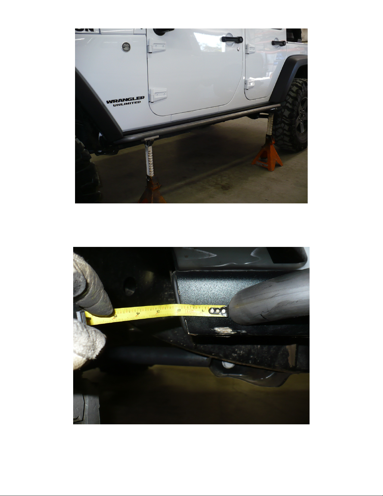
3) Shim and clamp the tube accordingly to level the rocker tube with the Jeep’s stock
rockers. We recommend positioning the tube equally front to rear on the stock
rocker guards (approximately 2” from each end), but again final fitment is up to
the installer.
Page 3
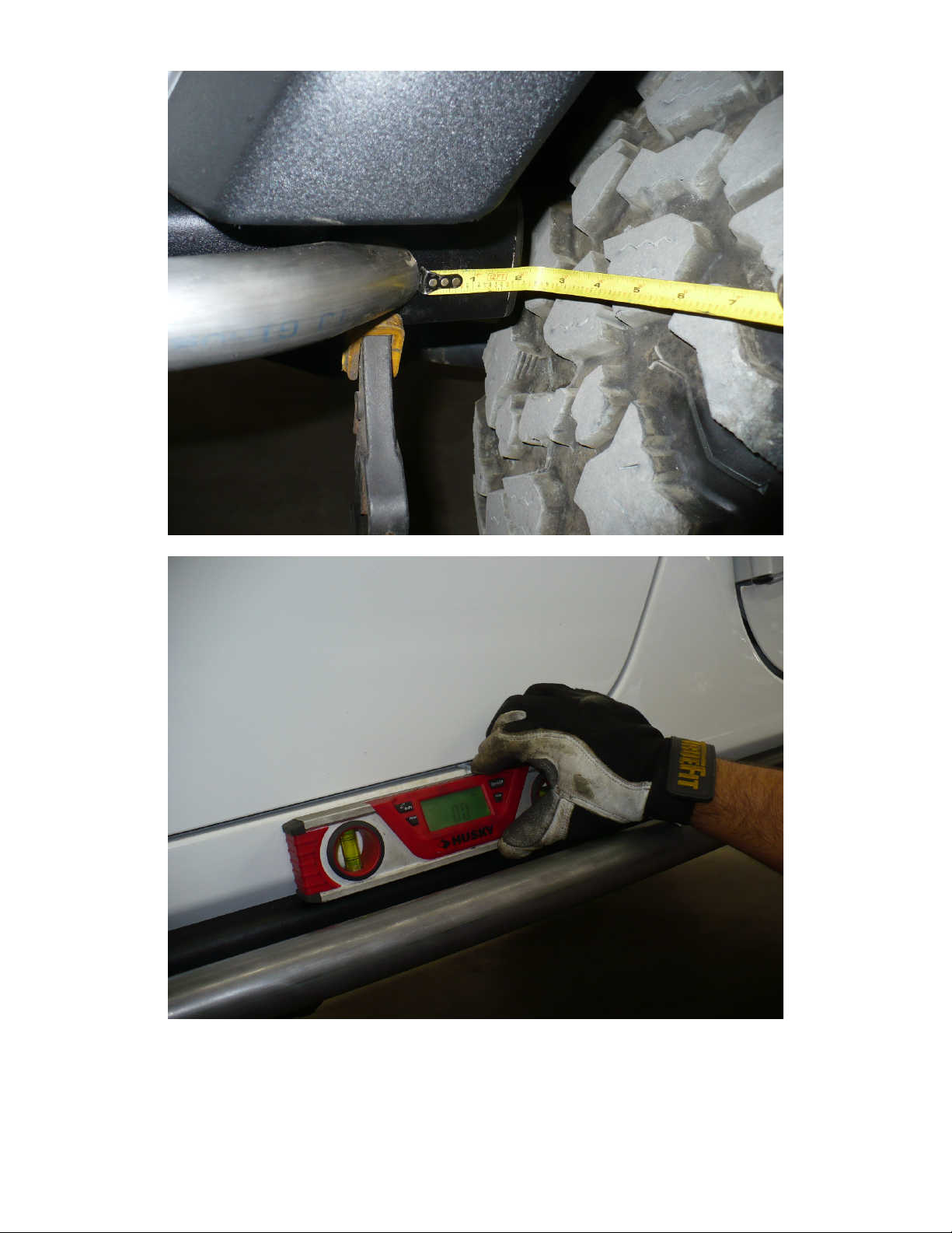
Rocker tube front to rear measurement
Match rocker tube to stock rocker
Page 4
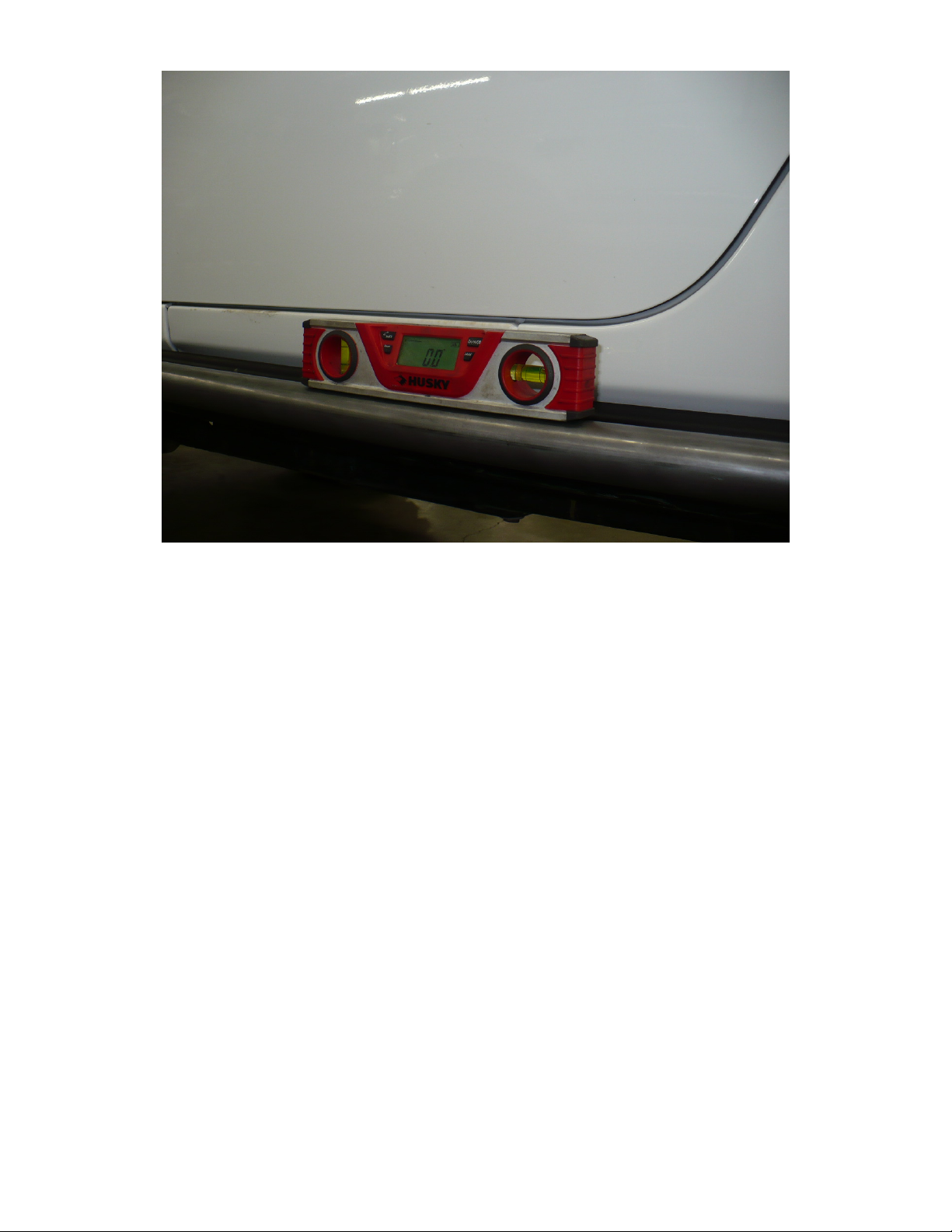
Rocker tube level with chassis
4) Once satisfied with the position of the tube, either clamp it in place so it will not
move, or clean up the paint as needed to throw some small tacks on each end of
the tube as to begin fitment of the flared steps included in the kit.
5) Each kit includes 4 flared hole steps. However, on 4 dr models, there are 2
different steps and orientation is critical for installation to go smoothly.
a. The steps are tapered on one side and thus are thinner on one end than the
other end. This is to match the rolled flare of the stock JK rocker tubes
b. Measure the width of the plates. One side should measure just under 3.0”
wide, while the other side measures 3.50”. The wider edges should be
pointing towards the ends of the vehicles, while the narrow edges should
be facing near each other. See image below for reference.
Page 5

Footplate reference / orientation
6) Orient the plates as shown with the flares pointing up. We recommend lining up
the back edge of the front plate with the body seam under the front door as shown.
Note- this is the rear seam on the bottom edge of the front door.
a. Some minor sanding / grinding of the steps may be needed for optimum fit
and finish due to variations from vehicle to vehicle.
Page 6

Front footplate fitment
7) As for the rear plates, push them as far back as they will go. The rear notch in the
plate should line up with the curve in the new rocker tube.
Rear foot plate fitment
8) Once satisfied with fitment and location. Take note and mark the areas which
need to be cleaned up for welding.
a. Remove paint as needed. Be sure to clean up all areas near the edges of
the plates as this is where the small rocker tie in tubes will be installed.
Page 7

Rockers ready to weld
9) With paint removed and ready to weld, tack weld the parts into place. Be careful
not to get any weld sparks onto the vehicle’s paint as this will damage the finish.
10) We suggest moving on to the opposite side of the vehicle at this point to match
everything left to right before proceeding.
a. Once everything is tacked in place, we recommend removing the whole
rocker guard assembly to finish installation.
b. There are three attachment points on each rocker. Each attachment point
has two 10mm nuts and one 13mm bolt securing it to the body. Remove
this hardware and pull the rockers off the vehicle.
Page 8

Rocker assembly tacked into place
Rocker attachment point.
11) With the rockers removed, place them on a solid work surface to finish
installation and welding.
12) The last things to install are the rocker tie in tubes. These small tubes provide
additional support and rigidity to the stock rockers. The tie in tubes are all the
Page 9

same length and will require grinding and individual fitment for proper
installation.
13) Grind / cut the flat end of the notched tie in tubes until they fit correctly in the
locations pictured below at the edges of each footplate.
14) Once installed and satisfied with fitment, fully weld everything in place.
a. Weld the main tubes, and rocker tie in tubes in place. We recommend
welding the tie in tubes directly to the footplates as shown below.
Page 10

15) Weld between the small hole cut outs in the footplates for a clean finish.
16) Paint or powder coat the rockers as desired and reinstall in the reverse steps of
removal.
Page 11

 Loading...