

Page 1
SYNERGY MFG. 870 INDUSTRIAL WAY, SAN LUIS OBISPO, CA (805) 242-0397
PPM-5310 JK REAR BUMPER INSTALL
INSTRUCTIONS
Version 1
GENERAL NOTES:
• These instructions are also available on our website; www.synergymfg.com.
Check the website before you begin for any updated instructions and additional
photos for your reference.
• The Polyperformance JK rear bumper system is a bolt on installation; it does
require drilling two holes on diver side frame rail.
1. Remove the spare tire and mount if you are installing the Poly Performance spare
tire swing out.
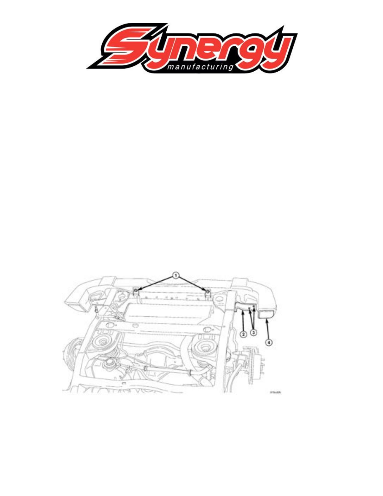
2. Remove the stock rear bumper, retain the stock side mounting bolts, the 4 bolts
will be reused. See Figure 1
Figure 1
3. Remove the stock tow hook from the passenger side frame rail if equipped.
4. If equipped with a stock receiver hitch, it can remain installed or it can be
removed for installation of the optional license plate skid plate.
5. Remove the stock license plate and mounting bracket from the tub. The new
bumper relocates the license plate and includes two new license plate lights.
Page 2
6. When removing the stock license plate mount, locate the wire for the license plate
light. The wire will need to be lengthened and spliced into the new license plate
lights prior to installing in the bumper.
7. With all the stock bumper components removed, locate the two holes on the
bottom of the passenger side frame rail that once held the tow hook in place. You
will need to drill holes in the driver side frame rail identical to the ones in the
passenger side. Measure the hole locations on the passenger side and transfer the
hole locations to the bottom of the driver side frame rail.
8. With the hole locations marked, drill the two holes with at least a 1/2” drill bit; a
slightly larger bit may be used to get the correct alignment. Do not exceed 5/8”
hole size.
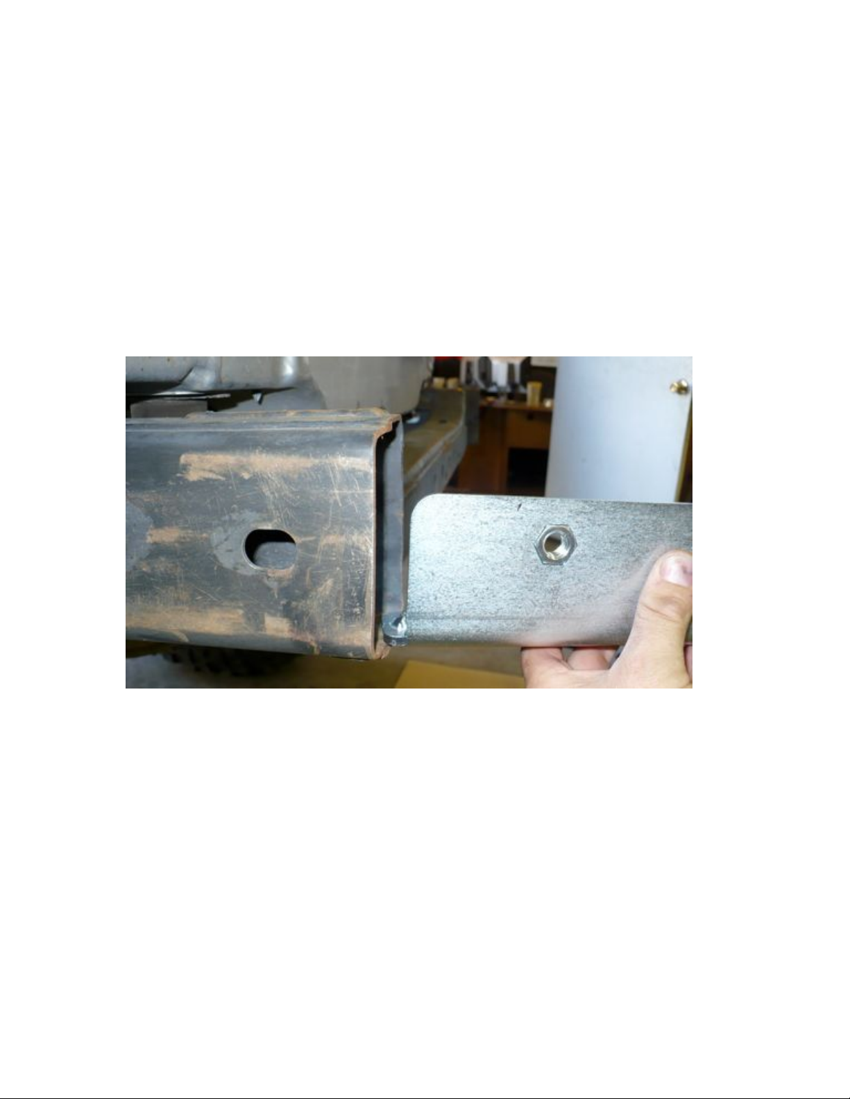
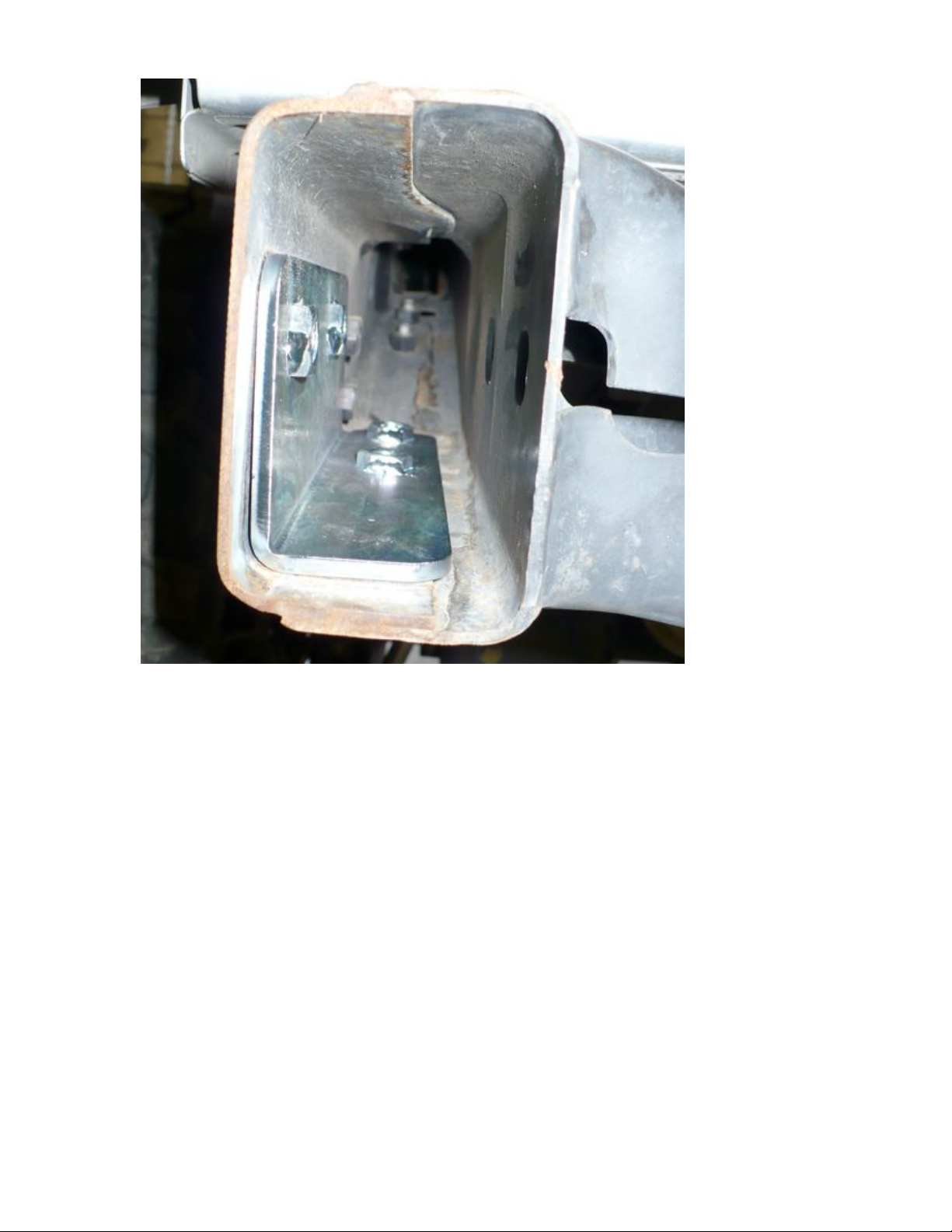
9. Install the bumper mounting plates into each side of the frame rail as pictured in
Figure 2 and 3.
Figure 2
Figure 3
Page 3
10. Line up the bracket holes with the holes in the frame.
11. Install the license plate with the four ¼” screws, push the new license plate lights into
the bumper as orientated in Figure 4.
Figure 4
Page 4

11. Now would be a good time to get the license plate light wiring figured out. You may
need to add a few feet of wire to the stock light wire and string the wire though the
bottom of the tub to the center of the rear frame crossmember. You can get the new
lights wired together and ready to plug in when the bumper is on the ground. This
will make them easier to hook up when the bumper is lifted in place.
12. With assistance, lift the new bumper into place. Plug in the license plate lights. Install
the supplied 1/2” x 1” bolts and washers through the bumper into the bumper
mounting brackets. There are 4 bolts and washers per side. Install the two stock
bumper mounting bolts onto either side of the bumper mount. Pictured in Figure 5
Figure 5
13. Check the alignment of the bumper with the back tailgate. Adjust it as needed, so
bumper is in line with the tailgate. Torque the eight ½” bolts to 80 ft-lbs and the four
factory bolts to 30 ft-lbs.
Page 5

14. If you are not using a factory installed hitch you can now install the license plate skid
plate to the center of the bumper.
15. Place the skid plate up to the bumper as shown in Figure 6. Insert the 1/2” x 4.5 long
bolts and washer combo through the back of the skid plate. Torque the bolts to 50 ft-lbs
Figure 6
The next section describes how to install the optional spare tire carrier PPM-5310-02-BK
Page 6

14. With the new bumper installed and the stock spare tire mount removed; you can begin
the installation of the spare tire carrier.
15. Remove the tire carrier, and all components from the packaging.
Included Items:
(1) Tire Carrier Frame
(1) Spare Tire Mount, with pressed in wheel studs
(1) Tire Carrier Spindle, with bearings, seal, castle nuts, washers, cotter pins and
dust cover.
(1) Tire Carrier Handle
(1) Tire Carrier Latch Base, with (1) 3/16” spacer (1) 1/8” spacer
(1) Hardware kit with the following parts:
(4) ½” X 1.25" Hex Head Bolts
(8) 1/2” Washers
(4) 1/2” Hex Lock Nuts
(5) 3/8” X 1.5 Hex Head Bolts
(8) 3/8” Washers
(5) 3/8” Hex Lock Nuts
(2) 3/8” Brass Washers
(2) 1/4” X 3/8 Flat Head Socket Cap Screws
(1) 10-24 X 1” Machine Screw
(1) 10-24 Nylock Nut
(1) Rubber Bumpstop
(1) Nylon Slider for Latch Base
(1) 3/8” pull pin
(1) 1/2” pull pin
16. Disassemble the zinc plated spindle, place bearings on a clean surface. Pack the
bearings with wheel bearing grease.
17. Have a helper hold the tire carrier frame upside down. Place the large greases bearing
into the tire carrier hub. The taper of the bearing should now be aligned with the hub
race.
18. The green seal is now installed on the bottom of the tire carrier hub. A rubber mallet
can be used to tab the seal into place. The seal body should be flush with the hub; it
will hold the bearing you just installed in place during the rest of the assembly.
19. Carefully slide the tapered spindle through the tire carrier seal, lower bearing and
hub.
20. The small upper bearing can on be installed onto the spindle and into the hub. Both
lower and upper bearing fit tightly on the spindle, they need to be aligned straight to
get the bearing to slid over the spindle.
21. Install the large, non zinc plated washer over the spindle. It will land on top of the top
bearing.
22. Install the large castle nut on the spindle. Torque the nut to 20 ft-lbs or tighter to get
the cotter pin hole to line up.
23. Figure 7 shows how the completed assembly should look when the spindle is installed
in the Tire Carrier Hub.
Page 7

Figure 7
24. Install the 1/2” pull pin onto the hub assembly. Grease the spring. We recommend
using loctite on the threads of the T-handle. Snug the pin into place using channel
lock pliers on the knurled housing.
25. You can now insert the tire carrier by placing the tapered spindle into the tapered hole
on the bumper. Install the zinc platted washer and castle nut. Torque the nut to 75 ftlbs and install the cotter pin to ensure the nut will not come loose. See Figure 8
Figure 8
Page 8

26. Check the spindle bearing pre-load by lifting the tire carrier. If there is any noticeable
up and down movement, tighten the top castle nut more. When a desirable pre-load is
set, install the cotter pin and top dust cap. The dust cap can be installed with a rubber
mallet or use a flat blade screw driver to tap the outer lip of the cap till the cap is flush
with the hub.
27. Swing the tire carrier to the open position and allow the pill pin to lock in place.
28. Retrieve the latch mount, shims, handle and remainder of the hardware kit.
29. Bolt the latch handle to the latch mount. Use the two brass washers on ether side on
the handle, use a 3/8” x 1.5 bolt and one top lock nut. The tightness of this bolt
determines how loose or tight the latch handle is. Tighten so the handle moves freely
but has no side to side play.
30. Install the 3/8” pull pin, grease the spring and shaft before inserting it into the
housing. Screw the pin into the housing and tighten lightly with a set of channel lock
pliers. We recommend installing loctite on the threads of the T-handle to prevent it
from coming loose.
31. Install the nylon slider onto the latch base using the 1/4” flat head bolts. Install the
rubber bumpstop suing the 10-24 x 1” machine screw and nylock nut. Tighten it
down until the bumpstop starts deforming.
32. Install the latch handle assembly onto the bumper using the 3/8” x 1” bolts, washers
and top lock nuts as pictured in Figure 7, torque to 30 ft-lbs. Use latch shims under
the latch mounting surface for the following spare tire sizes:
- 3/16” and 1/4” Shim for 35” tires
- 1/4” Shim for 37” tires
- No Shim for 40” tires
- Shims may need to be added or removed depending on combined tire/wheel weight.
33. Completely install the latch assembly onto the bumper as shown in Figure 9. The rear,
inside bolt will need to go through the bottom on the bumper to clear the bumpstop on
the latch assembly.
Page 9

Figure 8
34. Install the spare tire mounting bracket to the top of the swing out mount using the
four 1/2” x 1” bolts, washers and lock nuts. This can usually be installed in the
position that brings the tire closest to the body. Torque the ½” bolts to 50 ft-lbs.
35. If you purchased the optional third brake light, install the light onto the tire mounting
bracket and wire the light into your brake light system.
36. Install your spare tire into the three mounting studs using the original spare tie lug
nuts. Torque the lug nuts to 75 ft-lbs.
37. Now swing the spare tire carrier closed. Check to be sure that the bottom of the
carrier tube lightly contacts the plastic slider on the latch handle. If the carrier does
Page 10

not contact the plastic on the latch, you may need to install another shim under the
latch in order for the latch to operate properly.
38. Contact Poly Performance if there are any questions: 805-783-2060
 Loading...