

Page 1

SYNERGY MFG. 870 INDUSTRIAL WAY, SAN LUIS OBISPO, CA (805) 242-0397
PPM-5223 JK 4 DOOR B-PILLAR CAGE TIE IN KIT
Version 1.1
GENERAL NOTES:
• These instructions are also available on our website; www.synergymfg.com.
Check the website before you begin for any updated instructions and additional
photos for your reference.
• This is a weld in roll cage kit, all welding should be performed by an experienced
welder with proper welding equipment
• This kit can be used by itself or in conjunction with PPM-5221-A and/or PPM-
5224-A; 4 dr rear cage kit.
• This kit works with either a soft top or hard top.
• Use extreme care when welding and grinding in the interior of your Jeep, remove
or cover any components you do not want welding spatter or grinding sparks to
damage.
1. Remove the hard or soft top, if using a soft top, remove the door surrounds.
2. Remove the sound bar, roll bar covering, and roll bar padding in the B-pillar area.
3. Lastly, remove the carpet in the rear seat passenger foot well area. (This may require
removal of front seats)
4. With carpet removed, reposition front seats (if previously removed) and take note of
any floor insulation in the rear passenger foot well area. Mark out a 4” box from the
edges of the flat portions of the floor near the B-pillar trim.
Page 2
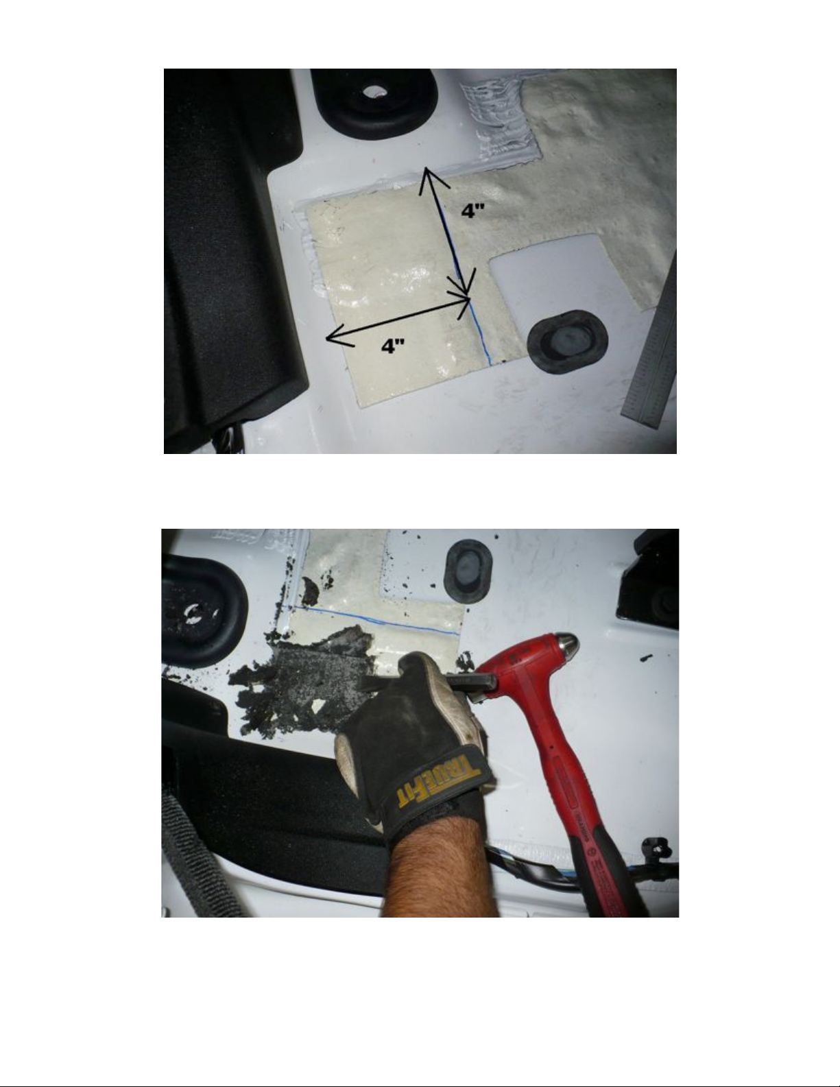
5. This area needs to be free of any floor insulation / sound deadening material before
we can fit the B-pillar floor plates. The easiest way to remove the floor insulation is
with a hammer and chisel. Using the chisel at a 30-45 degree angle to the floor, chip
away the insulation until it appears how it does in image 5.2 below.
Page 3
Img. 5.2
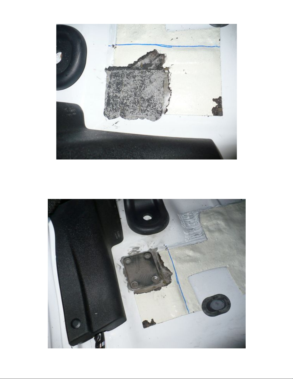
6. Clean up any remaining high spots or thick spots of glue by sanding. A 3” air sander
works well for this.
7. Once the B-pillar floor plate can sit flat as shown in Img. 7.1 be sure it is positioned
up against the flat corners of the floor. Next, mark and drill four 3/8” diameter holes
through the floor.
Img. 7.1
Page 4
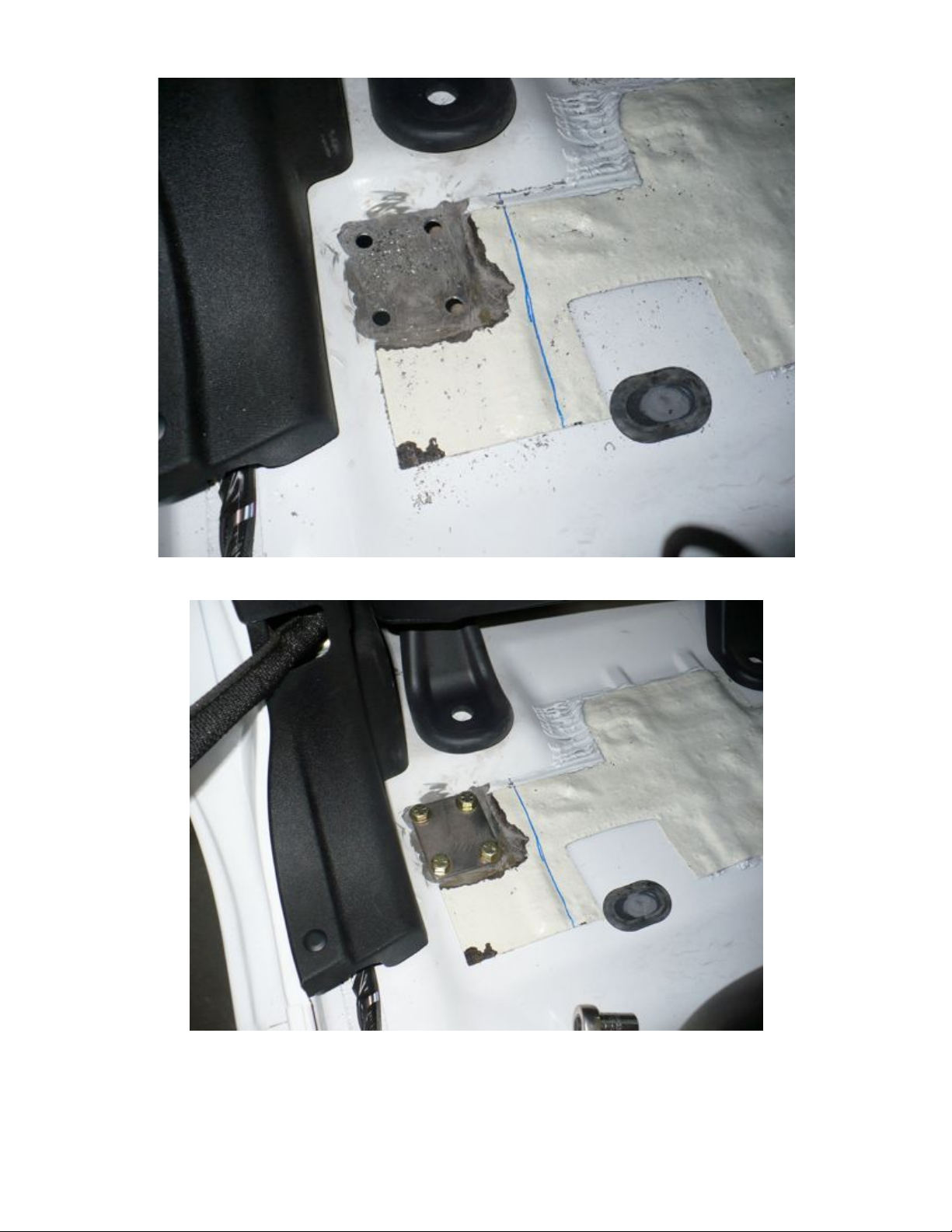
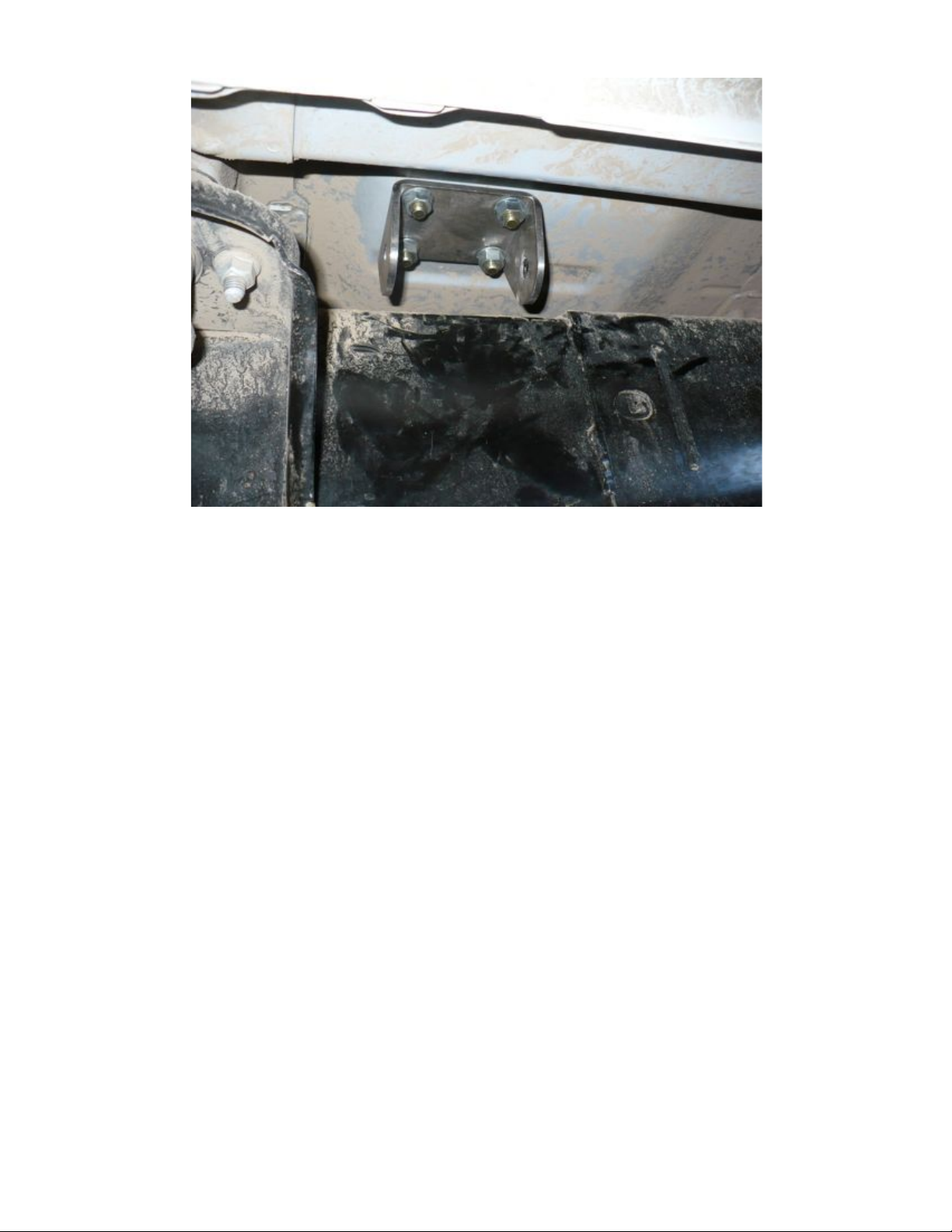
8. Bolt the B-pillar floor plate to the body with the bushing mount plate on the underside
as shown. Use a washer under the head of the bolt and a flange nut on the underside.
Page 5
9. Now, test fit the bushing isolated frame tie in by using the ½-13 x 5.0” long bolt
included in the kit.
10. Mock the frame tie in position and take note of where to remove paint on the frame in
preparation for welding. Do not weld at this time.
11. Next, we need to trim some of the factory B-pillar cross bar to fit the new B-pillar tie
in tube.
Mark a line 5/8” in and 4” long as shown in the images below.
**Note** these cuts were a minimum needed to allow us to fit a
tig torch in position for welding. Slightly more material may need
to be removed depending on weld technique used (Tig, Mig, Stick
etc.)
Page 6

12. Cut this piece out. Be careful to only cut the single layer of material and not to knick
the underlying B-pillar cross tube or other parts of the factory sport bar.
Page 7

13. Clean up any sharp edges made from the cut and prepare the area for welding as
shown below.
14. Now, fit the B-pillar tie in tube. Note they are L & R specific and are labeled as such.
Center the base of the tube on the floor plate.
Push the notch forward to just before it touches the plastic B-pillar
trim. This should be approximately 90 degrees to the factory sport
bar.
See images below.
Page 8

Page 9

15. At this point, be sure the tube is oriented correctly and the seat clears easily. It should
be able to slide all the way back and fully recline with the tube in position.
16. Once satisfied with fitment, tack the tube to the floor plate.
Page 10

17. At this time, it is a good idea to fit the harness bar (if planning to run it) and make
sure it fits correctly between the B-pillar tie in tubes. The factory sport bars vary
from Jeep to Jeep so be sure the harness bar fits with how the tie in tubes are tacked
in position. Adjust as needed to align notches.
18. When mocking up the harness bar, be sure it will be in a safe position to correctly
mount your shoulder belts to. Set the seat in a comfortable driving position for mock
up. Then follow the Crow diagram below to ensure proper placement.
For reference, see image 16.2 below for the measurements off our
Jeep when developing this cage kit. We measured 32” from the
floor plate to the bottom of the harness bar for proper mounting.
Page 11

Page 12

19. Once harness bar fitment is established, remove the tacked B-pillars from the vehicle
and fully weld the B-pillar to the floor plate. Allow welds to cool. Deburr welds as
needed and apply the desired color of paint to the bar. **Note** Leave the notch end
bare as well as the harness bar junction to allow for welding.
Page 13

20. If not using a form of tube clamp to make the harness bar removable (Synergy parts:
3113-150-125, 3222-150, 3112-06 or 3120-150 for example) be sure to paint as much
as possible before installation.
21. Reinstall B-pillar tubes as before and tack weld them to the factory sport bar.
22. Fit the harness bar as before. Be sure it is level with the vehicle and tack into
position.
Double check seat clearances.
Fully weld into position. Deburr welds as needed and paint with
the desired color.
23. Back to the underside of the vehicle. Reinstall the bushing isolated frame tie in and
tack into position. Tack securely as it is a good idea to remove the bushings from the
tie in before fully welding.
24. Fully weld the tie in bracket. Allow to cool and paint the desired color.
25. Reinstall bushings, sleeve and bolt the entire assembly together. Use a washer under
both the head of the bolt and the nylock nut. When complete, it should appear as it
does below in image 27.1
Img. 27.1
26. Reinstall the interior pieces. Secure the seats if removed and trim the carpet around
the B-pillar tube as needed. Trim the factory B-pillar foam to clear the added tie in
tube as shown below.
Page 14

27. Reinstall the remaining sport bar padding and trim the cover to fit around the tube.
Reinstall the sound bar and hard or soft top.
Page 15

28. Installation is complete.
 Loading...