

Page 1

SYNERGY MFG. 870 INDUSTRIAL WAY, SAN LUIS OBISPO, CA (805) 242-0397
5052- SYNERGY SUSPENSION UNIVERSAL REAR 4-
LINK KIT
Version 1.0
GENERAL NOTES:
• These instructions are also available on our website; www.synergymfg.com.
Check the website before you begin for any updated instructions and additional
photos for your reference.
• These instructions include only the link suspension kit, you will need to
accommodate steering, spring and shock mounts in addition
• This is a universal kit and will likely require modifications to these components to
fit your application correctly
• The installation of this suspension kit requires extensive cutting, grinding and
fabrication. Many of the major suspension brackets on the frame will need to be
cut off and ground smooth. A plasma cutter or oxy-acetylene torch works best
but you can also use a grinder with a cut off wheel.
• You will need basic hand tools, MIG welder a grinder with cut off wheel or
sawzall, floor jack or automobile lift, and two sturdy jack stands to complete this
installation.
1. Unpack the suspension components from the boxes, verify that all parts are intact and
in good condition.
2. Read all the following steps before beginning installation. If you do not have the
proper tools or ability to install the components properly do not attempt installation.
Find a creditable, local shop to do the installation work.
3. Take some baseline measurements of your existing suspension so you know what you
had, measure the distance from the axle to the frame at ride height, axle to the ground,
and axle location front to back.
4. Make a plan and take notes of what you want to change, i.e. move the axle rearward
4-6" is common.
5. Tack weld everything, do not finish weld any component until you have cycled the
suspension and checked that everything clears adequately.
FRAME LINK BRACKETS
6. Use a floor jack under the center of rear axle to lift the tires off the ground. Place
jack stands under each side of the rear portion of the frame rails to support the weight
of the vehicle. Raise or lower the floor jack under the rear axle to remove and install
suspension components.
7. Remove the rear suspension components and the entire rear axle assembly
Page 2
SYNERGY MFG. 870 INDUSTRIAL WAY, SAN LUIS OBISPO, CA (805) 242-0397
8. Cut off any suspension bracket on the frame that you will not be using, i.e. lower
control arm brackets, shock mount, spring mounts, track bar brackets, leaf spring
hangers, etc
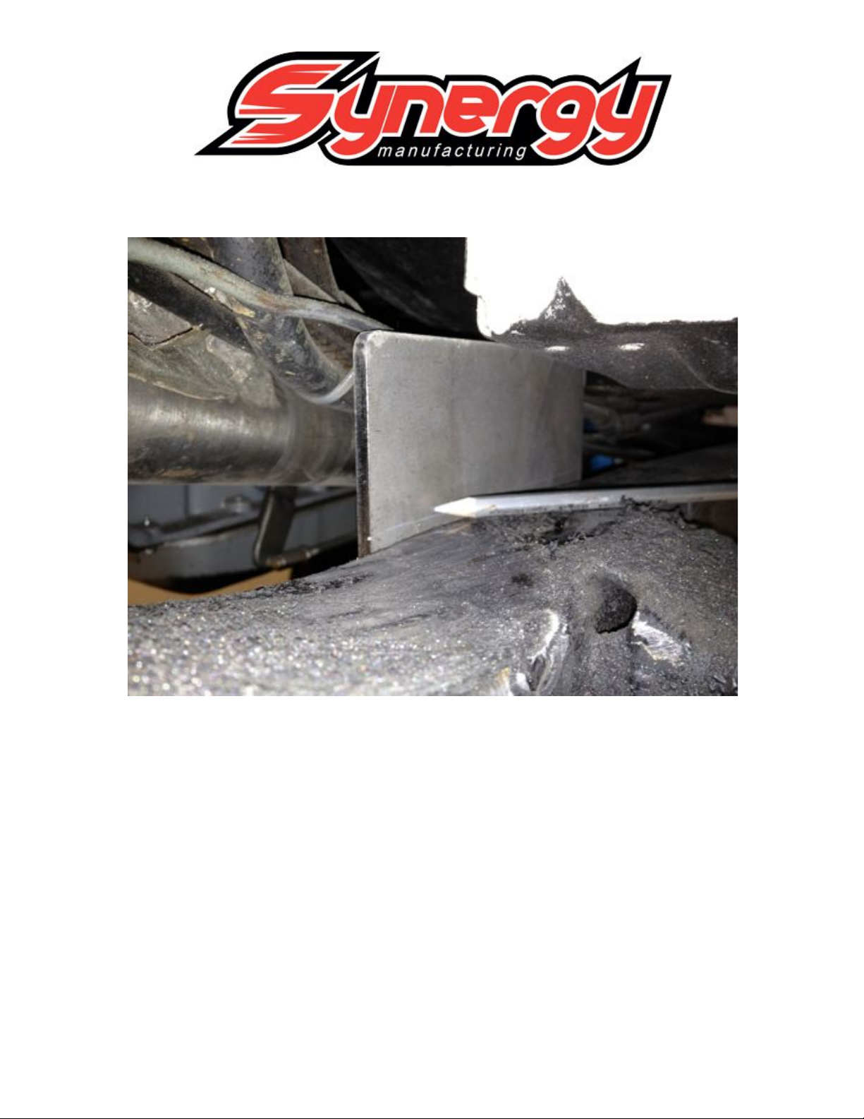
9. Position and clamp the new rear frame control arm brackets on the frame. The front
to back location is entirely up to you, on a TJ or YJ, up against the back of the T-case
skid plate is generally is where it goes. You may need to relocate or push the brake,
fuel lines above the frame control arm bracket.
10. Mark the bracket where the top edge of the frame is.
Page 3
SYNERGY MFG. 870 INDUSTRIAL WAY, SAN LUIS OBISPO, CA (805) 242-0397
11. Remove the control arm bracket and cut at the line.
Page 4

SYNERGY MFG. 870 INDUSTRIAL WAY, SAN LUIS OBISPO, CA (805) 242-0397
12. Reposition the control arm bracket to the frame and tack weld the upper plate on.
13. Remove the control arm bracket again and weld the top plate on.
Page 5

SYNERGY MFG. 870 INDUSTRIAL WAY, SAN LUIS OBISPO, CA (805) 242-0397
14. Reinstall and tack weld the control arm brackets on the frame. Double check the
front to back location and make sure they are the same side to side.
AXLE LINK BRACKETS
15. Cut off all or any unwanted suspension brackets from the axle housing. Use a grinder
with a cut off wheel, plasma cutter or oxy-acetylene torch. Grind the welds smooth.
16. It is best to set the axle on jack stands with a jack supporting the pinion to set the
pinion angle. Adjust the pinion to your desired angle, 10-15 degrees is typical for this
type of application.
17. Position the lower control arm brackets on the axle tube. These brackets are made for
a 3" axle tube, you may need to modify them to fit your axle tube if it's a different
size. This is not a set location and is up to you to find the optimum position.
Page 6

SYNERGY MFG. 870 INDUSTRIAL WAY, SAN LUIS OBISPO, CA (805) 242-0397
Typically the lower control arm brackets are 42-44" apart, center to center. Make
sure they angle inward looking from the top. Tack weld to the axle tube.
18. Mount the axle truss with the upper control arm brackets. This is typically mounted
with the top level. Tack weld to the axle tube
Page 7

SYNERGY MFG. 870 INDUSTRIAL WAY, SAN LUIS OBISPO, CA (805) 242-0397
LOWER CONTROL ARMS
19. Position the axle housing back under the vehicle on jack stands. Set the front to back
location and set the axle at ride height and correct pinion angle based on your notes
and dimensions from the beginning.
20. Measure center to center of the bolt holes of the lower control arm brackets. This will
be the length of the lower control arms. Thread the rod ends or Johnny Joints with
jam nuts into the threaded bungs. Only leave a couple of threads exposed past the
jam nuts. Measure from the center of rod end to the step on the threaded bung were
the tube is to be welded. Subtract two times this dimension from your center to
center measurement and this is the cut length of you tube.
21. Cut the lower control arm tubing to the length calculated above and tack weld the
threaded bungs in.
Page 8

SYNERGY MFG. 870 INDUSTRIAL WAY, SAN LUIS OBISPO, CA (805) 242-0397
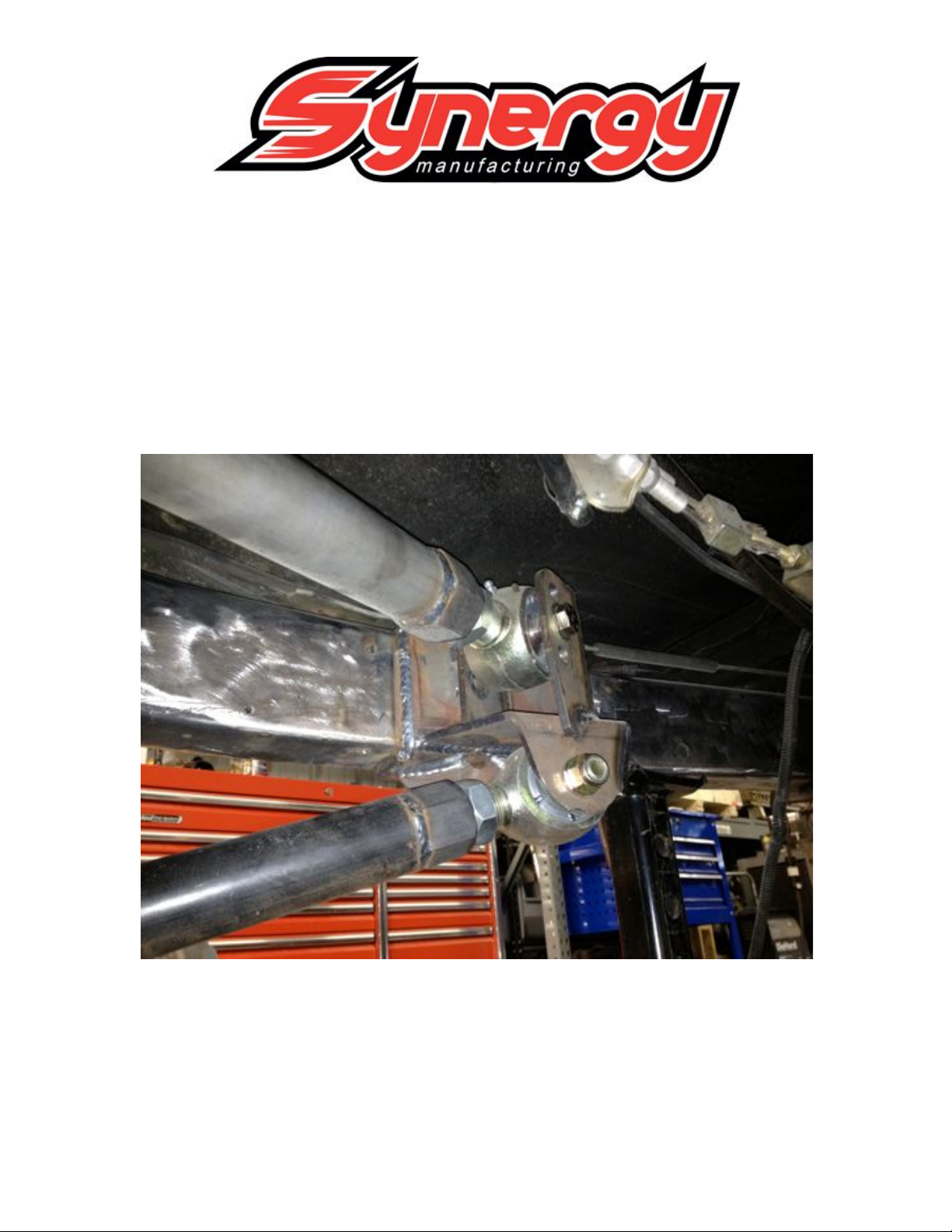
22. Install the lower control arms to the axle and frame brackets.
UPPER CONTROL ARMS
23. Measure center to center of the bolt holes of the upper control arm brackets. This will
be the length of the upper control arms. Thread the rod ends or Johnny Joints with
jam nuts into the threaded bungs. Only leave a couple of threads exposed past the
jam nuts. Measure from the center of rod end to the step on the threaded bung were
the tube is to be welded. Subtract two times this dimension from your center to
center measurement and this is the cut length of your tube.
24. Cut the upper control arm tubing to the length calculated above and tack weld the
threaded bungs in.
25. Install the upper control arms to the axle and frame brackets.
Page 9

SYNERGY MFG. 870 INDUSTRIAL WAY, SAN LUIS OBISPO, CA (805) 242-0397
FINAL CHECK AND ASSEMBLY
26. The following components are not covered in these instructions, but now would be
the time to address them
• Shock and spring mounts
• Anti-sway bar mounts
• Brake lines
• Parking brake cables
• Drive shaft angle or slip
• Differential breather length
33. Cycle the suspension and double check that everything clears satisfactorily.
34. Remove the control arms, axle housing and weld:
Page 10

SYNERGY MFG. 870 INDUSTRIAL WAY, SAN LUIS OBISPO, CA (805) 242-0397
• Weld the axle housing control arms brackets
• Weld the frame control arm brackets to the frame
• Remove the rod ends from the control arms and weld the tube bungs
35. Paint all components and reinstall, torque the 9/16 hardware to 150 ft-lb
36. Have the vehicle aligned by a professional shop. Check all hardware after 500 miles
of driving. We also recommend checking all hardware before and after all off road
trips to avoid failure from loose fasteners.
 Loading...