

Page 1

Page 2

-
1/26/11. Part no SY780A-222-02 650785
All rights reserved. to Synel Industries Ltd. Reproduction or use, without express permission of editorial or pictorial content, in
any manner is prohibited. No patent liability is assumed with respect to the use of the information contained herein. While every
precaution has been taken in the preparation of this manual, Synel Industries Ltd. assumes no responsibility for errors or
omissions. Neither is any liability assumed for damages resulting from the use of the information contained herein. Pictures in
this manual are for illustration purposes only. SY-785, SY-745 are sub-models of SY-780A, SY-765 is a sub-model of SY-760 are
trademarks of Synel Industries Ltd. All trade names referenced herein are either trademarks or registered trademarks of their
respective companies.
2
Page 3

-
Introduction................................................................................................. 3
Technical Specifications ............................................................................. 4
1Additional Technical and Interface Specifications..........................................................5
1.1Options..........................................................................................................................5
1.2Physical characteristics.................................................................................................7
1.3Power Requirements.....................................................................................................7
1.4Communication and configurations..............................................................................7
1.5Selection of the data entry function............................................................................10
Apparatus.................................................................................................. 11
1Front panel.....................................................................................................................12
2Bottom connection sockets............................................................................................13
3Internal components ......................................................................................................14
3.1Battery back-up modules............................................................................................14
3.2Memory ......................................................................................................................15
3.3RS-232/485 internal Card...........................................................................................15
Unpacking..................................................................................................16
Installation................................................................................................. 17
1Selecting the Terminal Location (Bluetooth and Wi-FI)...............................................17
2Mounting the terminal on a wall....................................................................................18
3Communication connections .........................................................................................21
Setting up the Terminal (Technician Mode)...........................................22
1Entering Technician Mode .........................................................................................23
2Entering SETUP mode ..................................................................................................23
3Resetting the Wi-Fi card................................................................................................34
4Hex table........................................................................................................................35
Host Computer Interfacing...................................................................... 36
1Installing communication cables ...................................................................................38
2Connecting your PC to the SY-65.................................................................................39
3Connecting the SY-65 to a connection box...................................................................40
3.1If communication problems occur..............................................................................40
4Making a multi-drop connection ...................................................................................41
4.1Cable from the terminal to the connection box ..........................................................42
1
Page 4

-
5terminal to RS-232 port direct connection ....................................................................43
Maintenance.............................................................................................. 44
1Physical Maintenance....................................................................................................44
1.1General........................................................................................................................44
1.2Badge Readers............................................................................................................45
1.3Fingerprint sensor cleaning and care..........................................................................46
2Calibrating the Real Time Clock (RTC)........................................................................50
3How to cause the memory to crash................................................................................52
3.1Location of jumpers....................................................................................................52
4Formatting the memory if a crash occurs......................................................................53
6Using POE.....................................................................................................................79
2
Page 5

-
Introduction
Synel SY-780A/760 terminals and their sub-models offer the
broadest range of effective time & attendance monitoring, shop floor
control, job costing, and access control applications.
The terminals have four mediums of access input: Fingerprint
identification and verification, magnetic, bar code, and proximity
readers.
The terminal features online/offline modes of operation and
communicates in real-time interface using TCP/IP protocol, which
makes it a comprehensive interactive system. It provides online
system management of employee reports as well as communication
of current employees' data.
Terminal communication programming employs Synel's user-friendly interface provided by SYncomm
or other advanced applications. This wide range of compatible communication applications supported
enable easily customizing the terminal to your unique requirements, while Synel's SAL compiler
enables flexible programming. Firmware can be upgraded remotely to facilitate maintenance.
The SY-780A/SY-760 terminals' mechanical design offers easy programming, while the back light and
32 character display allow quick and easy reading. The solid plastic casing and overall structure make
installation in an industrial environment simple and safe.The SY-780A has two sub-models, the SY785 AND SY-745. The SY-785 is offered with a variety of reader options, and supports 9,000
fingerprint templates for identification or verification purposes, with fast 1:1 and 1:N matching speed,
while the SY-745 is identical except for the number of function keys.
3
Page 6

-
Technical Specifications
The following table displays the technical specifications for the terminals
Model SY-780A SY-760
Sub-model SY-785 SY-745 SY-765
Memory 512 512 512
Programable Function keys 8 3 6
Numeric keys 10 10 10
Control keys Escape, Return, . (dot) and Clear
Browsing keys 2 2 2
Fingerprint on card Yes Yes No
Magnetic reader Yes Yes Yes
Wiegand reader Yes Yes Yes
Barcode reader Yes Yes Yes
Proximity reader Yes Yes Yes
Mifare reader Yes Yes Yes
Bluetooth Yes Yes Yes
Modem Yes Yes Yes
TCP/IP Yes Yes Yes
Printer Yes Yes No
I/O 2/2 2/2 2/2
Wi-Fi Yes Yes Yes
2
C
I
44 4
(read only)
Yes Yes No
Wiegand output Yes Yes No
Alpha keyboard Yes Yes No
POE Yes Yes Yes
4
Page 7

-
1 Additional Technical and Interface Specifications
• 32 character LCD with back light display
• 512K of protected RAM
• Protected Real Time date/time clock
• Non-rechargeable lithium battery (capacity: up to 3 years) for the memory and Real Time clock
• Rechargeable backup battery for operation with auto shut-off for use during power outages
• RS-232 and RS-485 communication
• Two relays for bell, door, etc
• Two sensors (door monitoring)
• Variable baud rate - 1200 to 115000 bps
• Printer support
1.1 Options
• Fingerprint reader
• FPU-S (optical sensor)
• Template size 384 Bytes (reducible to 256 bytes)
• Template capacity 9,000 at 4MB flash
• Encryption 256 bit AES (fingerprint data protection)
• Resolution 500 (dpi)
• Image size 280 x 320 (pixel)
• FPU-S (Capacitance) sensor
• Template size 384 Bytes (reducible to 256 bytes)
• Template capacity 9,000 at 4MB flash
• Encryption 256 bit AES (fingerprint data protection)
5
Page 8

-
• Resolution 500 (dpi)
• Image size 280 x 320 (pixel)
• Reader Types:
• Bar-code slot reader model (Codes: 128, 2/5, 3/9, UPC-EAN)
• Magnetic (Track I, Track II, Track III)
• Proximity reader (125 KHz)
• Mifare reader (13.56 MHz)
• Wiegand 26/27/34/36/37/44/48bit (as of version 6.201)
• 14400 bps internal modem
• full compatibility to: v.32bis, v.32, v.23, v.22, v.21, Bell 212A and Bell 103
to use a modem JP1 of the modem card must be in set to default state (1-2) see “Jumpers” on page 69 for additional information
about setting the jumpers.
• Net connection
• Ethernet (10BASE-T/100BASE-T or AUI)
• POE (Power over Ethernet)
For information for using POE see “Setting the terminal for Using POE (Power over Ethernet)” on page 78.
• Wireless Wi Fi (802.11b)
• Bluetooth Class II
6
Page 9

-
1.2 Physical characteristics
Depth 9.5 cm
Height 17 cm
Width 25 cm
1.3 Power Requirements
• Voltage: 115/230 VAC
• Back-up battery - rechargeable, included
• POE - 802.3 af
1.4 Communication and configurations
1.4.1 Communication parameters
Communication between the host and terminals is performed under an asynchronous mode. The baud
rate is programmable, enabling rates from 1200 to 115000 bps.
1.4.2 Multiple terminal configuration
RS-485 communication enables you to connect up to 32 terminals to a single COM port and/or to
extend the cabling distance to up to 1,000 meters (3,280 feet) using 9600 baud via an RS-485 multi-
7
Page 10

-
drop line. RS-485 communication uses two wires as opposed to RS-422 communication, which uses
four wires.
1.4.3 Point to point configuration
A single terminal, equipped with RS-232 communications, can be connected directly to an
asynchronous RS-232 port. If RS-232 communication is used, only one terminal may be connected to
each COM port and cabling distances should not exceed 50 meters (160ft).
1.4.4 Network connections
The terminal can be connected to one of the following communication networks:
Ethernet - For this type of communication, an IP address is defined for every terminal, enabling
communication with each terminal in TCP/IP protocol.
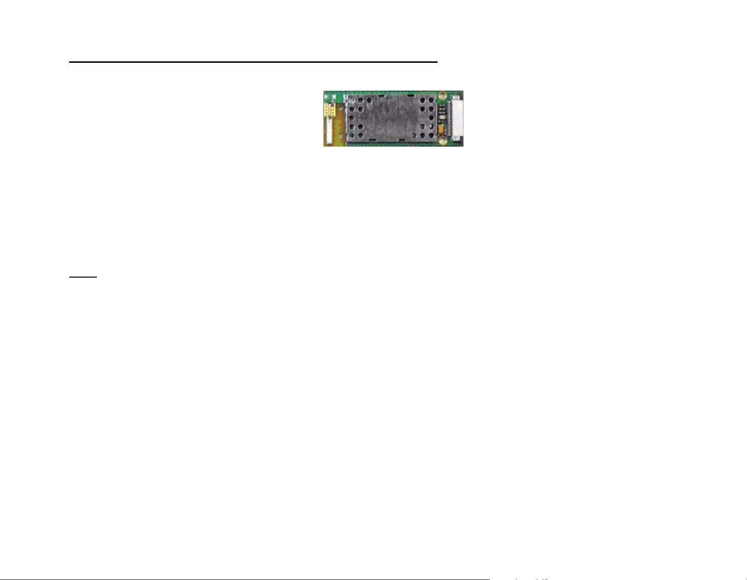
Bluetooth - For this type of communication, a pin number is specified, to authorize the connection.
8
Page 11

-
Technical Specification Table
Card access current ~5V
Module current ~3.3V
Idle power consumption 15mA
Working power consumption 40-75mA
Ripple on card 5m V P-P
Ripple on module 5m V P-P
Pressure on power source at
~7.36V
complete terminal capacity
with an internal BT or BAT
reader without an FPU or
external reader
Complete power consumption
from power source at
complete terminal capacity
with an internal BT or BAT
I(JP11)<1A(~250mA)
I(V1)<<1A(small)
~350mA
I(BAT)~100mA
reader without an FPU or
external reader
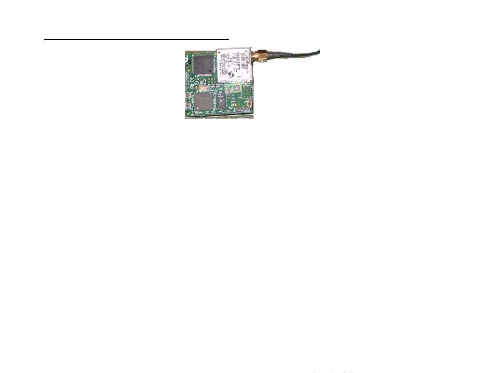
Wi-Fi - For this type of communication, an SSID is specified, to authorize the connection.
9
Page 12

-
Technical Specification Table
Card access current ~5V
Module current ~3.3V
Idle power consumption 200mA
Working power consumption 390~420mA
Ripple on card 6m V P-P
Ripple on module 5m V P-P
Pressure on power source at
~7.04V
complete terminal capacity
when using WI-FI/ internal
magnetic reader/ external CCD
reader and FPU.
Complete power consumption
at complete terminal capacity
when using WI-FI/ internal
magnetic reader/ external CCD
reader and FPU.
~350mA
I(JP11)<1A(~250
mA)
I(V1)<<1A(small)
I(BAT)~100mA
1.5 Selection of the data entry function
The terminal is ready for operation when a data entry function has been selected (after it was
programmed). The prompt of the selected function will be displayed on the second line. To select a
function, press the desired function key prior to entering the data.
10
Page 13
-
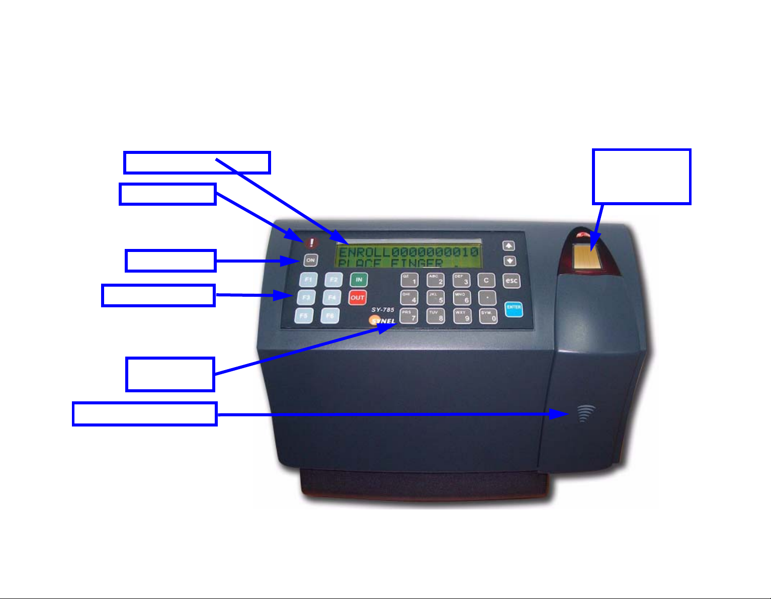
Apparatus
This terminal series is enclosed in a rugged plastic molded casing and is secured to the wall using four
screws and a removable panel.
32 character LCD
Alarm light
ON button
Function keys
Numerical
keyboard
Internal reader
Biometric
fingerprint
reader
• You can click on the feature
names to jump to their
explanation.
11
Page 14

-
1 Front panel
32 character LCD
32 character LCD
with a back light display is located in the upper part of the front panel. Two arrow keys are located
to the right of the display panel for line up and line down maneuvering.
Alarm light
located to the left of the display. The alarm light is an LED that lights up when:
Half of the memory has been used up
If the terminal is defined as “On-Line” and has lost communication with the host (no pooling command has been
received from the host for more then the value of parameter 8 in SYS table)
The light blinks when the memory is full or when the terminal has not been programmed.
ON button
The ON button enables a 15 seconds (modifiable using program) manual operation.
Function keys
Eight function keys are located on the left, below the display, and are marked as follows: IN- ,OUT- , F1, F2,
F3, F4, F5, and F6.
Numerical keyboard
A numerical keyboard of fourteen keys, including Return, Escape, and Clear is located in the lower center of the
front panel.
Biometric fingerprint reader
A Biometric fingerprint reader of FPU-s or Mv1200 type which supports thousands fingerprint templates for verification and identification. FPU is minutia based and uses the following technology:
• Optical sensor
• Capacitance sensor
• Authentec sensor
Internal reader
Internal badge reader/bar code/proximity reader.
12
Page 15
-
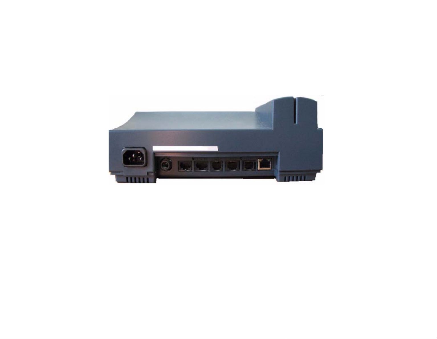
2 Bottom connection sockets
The bottom of the terminal contains connections sockets for all external connections. Connection
cables can be inserted through the round opening in the mounting panel, or from the bottom.
Information about connecting the sockets can be found on page 18.
The socket openings for external connections reside at the bottom of the panel from left to right:
•Power
•Reader 1
•Reader 2
2
C – I/O Extension (SY-785 only)
•I
•Network
• Serial – Serial port connection for printer
• Host – RS-232/RS-485
13
Page 16

-
3 Internal components
3.1 Battery back-up modules
The terminal has two back-up battery modules, one for the real time clock memory and the other for
operation during a power failure.
The standard memory back-up module is a lithium battery, which will keep the internal clock running
and the memory intact, for 30 days during a power failure.
Warning!
There is a risk of explosion if the lithium battery is r eplaced by an incompatible battery. You must dispose of used batteries as per manufacturer’s instructions.
The back-up battery provided (in addition to the standard memory back-up) is a self-recharging
system which allows the terminal to be operated during a power failure. The battery provides power
for one and a half net hours of use. A shutdown timeout feature enables the terminal to operate for
more extended periods of time.
There are two types of timeout shutdowns:
• The firmware default timeout of 15 seconds. This option is used if the terminal has not been
otherwise programmed (to a different timeout), if the application specifying otherwise has not been
loaded or if there is an error in the application.
14
Page 17

-
• The user defined timeout shutdown defined by programming the terminal using the SY protocol.
Once this option is uploaded to the terminal it is used at starting the terminal at Power On.
The default firmware battery shutdown timeout is 15 seconds. This timeout is used unless a different
timeout has been programed to the terminal using the Synel Protocol and uploaded to the terminal.
During a power failure, the user presses the battery key to activate the terminal. Data can then be
entered and stored in the terminal memory. The timeout will cause the terminal to shut down
automatically after the last use of the terminal, until the battery key is pressed again.
3.2 Memory
As a standard feature, the terminal contains a 512 Kb user memory providing storage for data from
more than 50,000 simple operations. This number depends on the length of the programming tables
contained in the memory, and the complexity of the collected data.
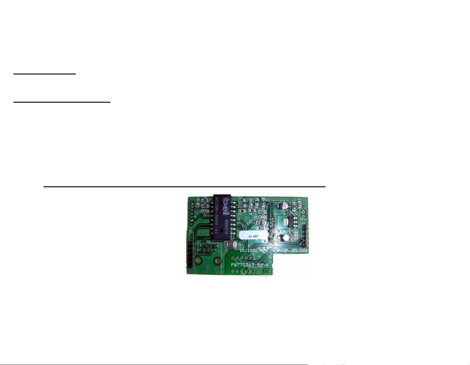
3.3 RS-232/485 internal Card
This card provides an RS-232/485 serial interface.
15
Page 18
-
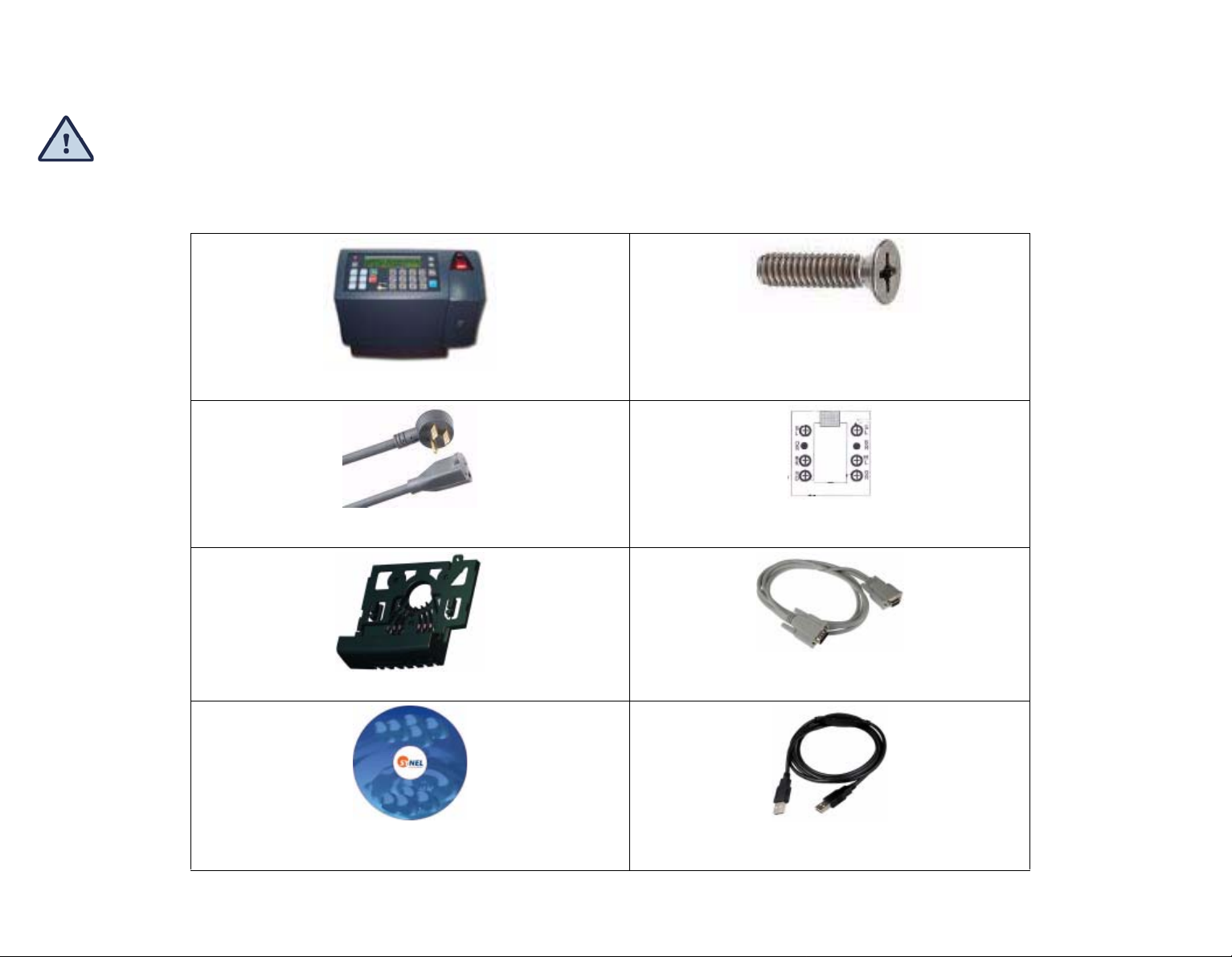
Unpacking
Check the box and contents for signs of damage that may have occurred during shipment.
Don’t throw away the box or any of the packing materials.Contents
The terminal package contains:
Phillips flat head 4x50 mm screws & anchors
(3 x brick/cement 3 x plaster walls)
Terminal
Detachable power cable
Mounting and connectors' cover panel
User guide on CD
connecting/splitter box (included only when network
communication is not available)
Short RS-232/485 communication cable (included only when
network communication is not available)
Short TCP/IP communication bridge cable (included only
when network communication is available)
16
Page 19

-
Installation
1 Selecting the Terminal Location
(Bluetooth and Wi-FI)
When selecting a place to install a terminal with wireless network
communication (Bluetooth and Wi-FI) you need to consider environmental
factors that effect the connection. The optimal location is where:
When selecting a place to install a terminal with wireless network communication (Bluetooth and WiFI) you need to consider environmental factors that effect the connection. The optimal location is
where:
• The connection to the terminal is not blocked by walls or metal obstacles. This can be done by
standing at the location where the terminal is to be installed and viewing the area where the
terminal is to have a connection with and make sure that it is clear.
• The antennas should are positioned so that they are parallel to one another. If there are obstacles
between the terminals. the antennas should be positioned for the best clear connection between
them. For example, at floor level below the obstacle or at ceiling level abo ve the obstacle, especially
with metal obstacles.
• For Bluetooth, use the terminal Quality option to check the connection quality. See “Setting up the
Terminal (Technician Mode)” on page 22.
• Do not install the terminal in a location where people gather and linger since they, too, block the
connection and also as to not expose them to radiation.
17
Page 20

-
2 Mounting the terminal on a wall
Make sure the unit is not plugged into a power source. If you have already connected
your terminal to a PC, disconnect it. You can reconnect it after you have completed
mounting the unit.
The terminal contains computer components. It should not be mounted where it will be exposed to extreme h eat or cold, water, steam,
violent vibrations, high electromagnetic
radiation including high voltage power lines and electrical equipment.
Step 1:Select a location for the terminal. The following guidelines will help you find the best place for the terminal:
•The terminal should be placed by an easily accessible power outlet.
•Make sure that there is enough space around the terminal for the communication cabling.
•Do not place the communication cable near a source of electromagnetic radiation or r adio interference such as
power lines,
large machinery, etc.
•If the communication cable is to be wired through the wall, make sure that it is safe to drill a hole at the
desired location.
•For best usability the terminal should be mounted at employee eye-he ight. The recommended height is 140cm
(4’7”).
18
Page 21
-
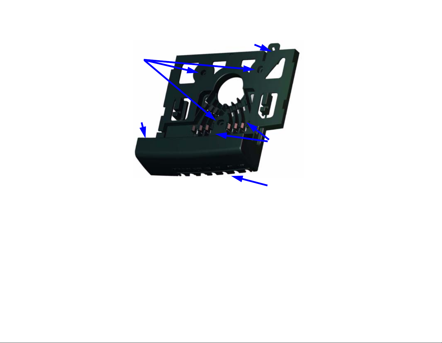
Step 2:Remove the back mounting panel by sliding it to the side and pulling it out.
E
A
B
F
C
D
A - Screw holes - for screwing the mounting panel in place.
B - Entrance for cables wired from the wall.
C -Clasps for holding cables in place.
D -For cable entering terminal from below.
E - security fastener.
F - Electric socket.
Step 3:Prepare the wall for mounting by placing the panel on the wall as a template and mark the place for drilling the
19
Page 22

-
holes (A).
Step 4:Drill holes using a 6 mm. (1/4”) drill bit.
Live wires in the vicinity may contain 115V or 220V.
Make sure not to drill into any live electric wires. Overlooking this warning may result in harmful contact with an electrical
current.
Step 5:The cables can be wired through the wall and positioned in the clasps (C) to the bottom of the terminal where
that are connected, or be wired directly from the bottom of the terminal (D).
Step 6:Position the panel so that all of the wires are in place and screw the panel to the wall.
Step 7:Wire all of the cables through the mounting panel and position the electric socket in it’s place in the mounting
panel (F).
Step 8:Connect the communication cables to the terminal.
Plug one end of the communication cable into the communication socket of the terminal. If an internal modem has
been added and the modem is used, plug the RJ-45 connector of a standard telephone cable into the telephone line.
Do not use the communication cable.
Step 9:Slide the terminal into place.
Step 10:Screw the security fastener into place (E).
20
Page 23

-
3 Communication connections
Step 1:Select a location for the connection box.
The box must be positioned where both the communication line and the terminal can be connected to it. The
terminal should be placed near the connection box, and must be within the reach of the short RJ45 cable.
Step 2:Plug the communication cable from the terminal into the connection box.
Step 3:Wire an additional connection for Ethernet.
21
Page 24

-
Setting up the Terminal (Technician Mode)
The terminal is setup in Technician mode that is described in this chapter.
To enter Technician mode you can either swipe an authorized badge or press the up/down
keys simultaneously six times.
Use the Enter key to scroll between screens, and the line UP/DOWN keys for moving between
options within the selected screen.
To return to the previous screen use the key. To exit technician mode double-click the Enter key.
Follow the steps in this chapter to set the terminal to your preferences.
C
22
Page 25

-
1 Entering Technician Mode
Swipe an authorized badge or press the UP/DOWN keys simultaneously 6 times.
The display screen flashes and then displays the version then changes to display the TECHNICIAN
MODE and the time and date alternately, (time&date are adjusted from a PC).
2 Entering SETUP mode
When you enter Technician mode you can either EXIT or SET. Choose SET.
Adjusting the Real time clock - RTC (N/Y)
This adjustment option is for internal clock calibration purposes.
Setting the date and time
The date is in DD.MM.YYYY format
Note: Setting date and time is enabled only when defining the system parameter in the SYncomm
software: Edit Program--> System--> Badge type choose S (System Administrator
Adjust host baud rate
Available baud rates: 9600, 19200, 38400, 57600, and 115200.
Adjust fingerprint unit baud rate
Available baud rates: 9600, 19200, 38400, 57600, and 115200.
Adjust printer baud rate
The available baud rates are: 9600, 19200, 38400, 57600, and 115200.
Adjust station ID
)!
23
Page 26
-
The Station (terminal) ID is the terminal’s address on a communication line. It enables multi-terminal
communication. Any number from 0 to 31 may be used as the terminal ID. Again, scroll to the
required Station ID number.
Modem rings
Choose either the number of rings or N for no rings.
Network connection
Programming the network connection requires addressing several sub-topics. The main screen enables three modes:
N for no connection,
-
- B for 10/100Base
- D for Bluetooth card Class 1
- F 10/100Base for answering when the terminal has been addressed
E for WIFI
-
Setting up Network Connection B or F = 10/100Base card:
Polling Y/N
For polling the user will be asked to choose between Y and N. Then, the terminal will send data to the server
as per the Polling sec. definition.
Polling Sec
Determines the frequency of data transmission to the SY-Server software. If your terminals are not in online
(query) mode, define the polling time as approximately 10-20 sec. Otherwise, raise polling time to avoid net-
24
Page 27

-
work collisions. Use the numeric keys to define your required polling time.
MAC SEND (Y/N)
If you want to confirm sending your terminal’s network MAC address to the host. Then after exiting technician
mode the terminal will send the host a “Hardware configuration network” message informing it of its MAC
address, IP etc.
My MAC Address
Displays your MAC address on your terminal’s prompt. here your terminal’s MAC address will be displayed.
My IP Address
Press line up/down to view the TCP/IP address of the terminal. Use the numeric keys to enter the IP Address.
Gateway Address
Press line up/down and key-in the required gateway address.
Remote Address
Press line up/down to view the TCP/IP address of the personal computer on which the SY-Server runs. Use the
numeric keys.
Subnet Mask
The subnet mask is the network address plus the bits reserved for identifying the subnetwork. Use the
numeric keys to determine the terminal’s subnet mask affiliation within your local net.
My Port
TCP/IP enables connecting multiple applications via the same address. The port number selected here is the
application identification number used by the computer when communicating with the terminal. Synel applications use the default port number = 3734 (a designated Synel port). However, you may change this according
to your specific needs.
Host Port
Synel applications use the default port number=3734. However, you may change this according to your specific needs. Use the numeric keys to change the port number.
Disconct Sec
Disconnect seconds defines the number of waiting seconds before reverting to offline mode. Click 03 to enable
a fast disconnection.
DHCP (Y/N)
To automatically assign a dynamic IP address to your terminal choose Y.
Note: If no IP address was defined under My IP Address, then you must use DHCP, so the only option is Y.
25
Page 28
-
Network connection D = Bluetooth card Class 1:
The range of the card is up to 100m. It requires installation of the relevant drivers in your PC.
Set/Link Y/N:
Device name: SYNEL-xxxx, you must fill-in a unique number for this terminal
PIN code (Y/N): choose Y.
PIN code length (1-12): PIN CODE + Length of PIN CODE
PIN code: enter the pin code.
Discoverable: choose Y
Link:
Enables checking the communication between the terminal and the PC.
1. You must establish a connection via SYNCOMM
2. Than in your terminal under Link | Read Link Parm choose Y.
3. Quality of transmission will be displayed on your prompt as a
progress bar. As per the scale status you can relocate/readjust your terminals location.
26
Page 29
-
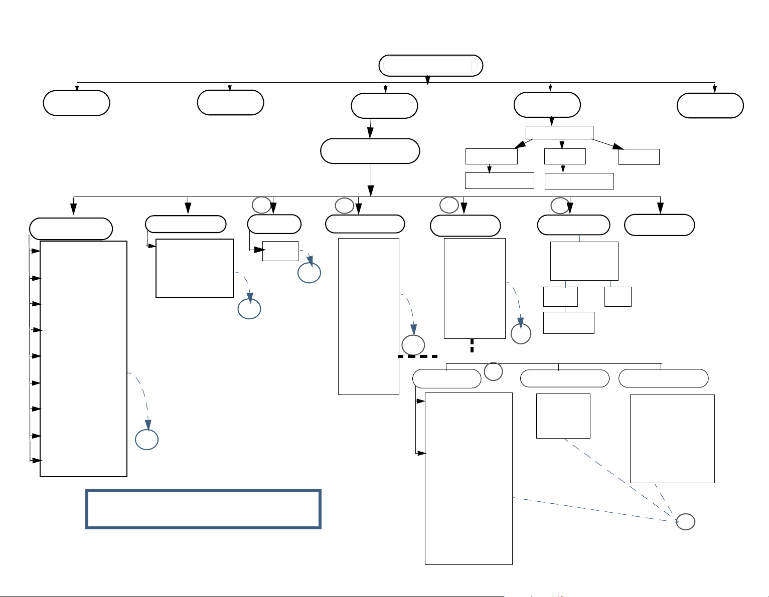
Network connection E = WI - FI card:
The following diagram in the next maps out the flow through Technician mode setup for WIFI.
After setting Authentication and Encryption you get content sensitive settings based on your previous
settings.
You can click the diagram nodes to jump to their explanation below.
27
Page 30
-
Main Settings
Polling
TCP/IP Settings
My MAC
My IP Address
Gateway Address
Remote Address
Subnet Mask
My Port
Host Port
Disconct Sec
DHCP
• Click on the nodes to jump to
MAC
A
Keyboard type
Input Keyboard
- Alphanumric
- Hexidecimal
B
SSID
SSID
B
A
their explanation below.
Network settings
C
Authentication
C
Set NIC
Open
Shared Key
WEP Auth
WPA PSK
WPA Auth
LEAP
Encryption
D
Context sensitive to Authentication and Encryption settings
WEP-Keys
WEP Security
- NO
- 64
- 128
WEP Key
- Key1
- OK
- Key2
- OK
-...
(up to key 4)
Press Enter key to
exit
Password
Enter Password
D
Open
WEP
CCMP
TKIP
E
Default
Reset
Enter Password
Reset
PleaseWait...
F
Save & Exit
S a v e c h a n ges?
Yes
Password
E
Pre-shared (PSK)
PSK
Apha
Hex
Exit
Exit
Exit no save
Y/N
No
User/Password
User:
<new user name>
-OK
Pswd:
<new password>
-OK
F
28
Page 31

MAC
Back to WIFI diagram
MAC (Y/N) - If you want to confirm sending your terminal’s network MAC address to the host. Then after exiting technician mode the terminal will send the host a “Hardware configuration network” message informing it
of its MAC address, IP etc.
Polling
Back to WIFI diagram
Polling (Y/N) -For polling the user will be asked to choose between Y and N. Then, the terminal will send data
to the server as per the Polling sec. definition.
Set NIC
Sets the content sensitive Network settings for WIFI.
TCP/IP Settings
Specifies the TCP/IP settings. Set by drilling down and selecting the parameters:
My MAC
Back to WIFI diagram
Confirms sending the terminal network MAC address to the host. After exiting technician mode the terminal sends the host a “Hardware configuration network” message informing it of its MAC address, IP etc.
My IP Address
Back to WIFI diagram
Press line up/down to view the TCP/IP address of the terminal. Use the numeric keys to enter the IP Address.
Gateway Address
Back to WIFI diagram
Press line up/down and key-in the required gateway address.
Remote Address
Back to WIFI diagram
Press line up/down to view the TCP/IP address of the personal computer on which the SY-Server runs. Use the numeric keys.
Subnet Mask
Back to WIFI diagram
The subnet mask is the network address plus the bits reserved for identifying the subnetwork. Use the numeric keys to determine the
terminal’s subnet mask affiliation within your local net.
My Port
Back to WIFI diagram
enables connecting multiple applications via the same address. The port number selected here is the application identification number
used by the computer when communicating with the terminal. Synel applications use the default port number = 3734 (a designated
Synel port). However, you may change this according to your specific needs.
Page 32

-
Host Port
Back to WIFI diagram
Synel applications use the default port number=3734. However, you may change this according to your specific needs. Use the
numeric keys to change the port number.
Disconct Sec
Back to WIFI diagram
Disconnect seconds defines the number of waiting seconds before reverting to offline mode. Click 03 to enable a fast disconnection.
DHCP
Back to WIFI diagram
To automatically assign a dynamic IP address to your terminal choose Y.
Note: If no IP address is defined under My IP Address, you must use DHCP.
Keyboard type
Specifies if the input keyboard is an Alphanumeric or Hexidecimal keyboard.
SSID
Back to WIFI diagram
(Service Set Identifier) - Entered in HEX form. Up to 26 characters.
The sequence of characters identifying the wireless local area network, allowing the stations to connect to a
specific network when multiple independent networks operate in the same physical area.
Authentication
Back to WIFI diagram
Specifies the method of authentication. Set by drilling down and selecting the parameters:
Open
Open (Entered in HEX form.)
WiFi WEP
None
64 bit
128 bit
Shared Key
Back to WIFI diagram
Set by drilling down and selecting the parameters entered in HEX form.
Open
When chosen the following is later
WEP Security
choose:
30
Page 33

-
None
64 bit (total allowed characters: in Hex 10 in Ascii 5)
128 bit (total allowed characters: Hex 26 in Ascii 13)
WEP Key
Specify the number of the key in the sequence of 4 keys.
WEP Auth
Back to WIFI diagram
WEP 802.1x authorization is set by drilling down and selecting the parameters.
Entered in HEX form.
WEP
Up to 26 characters.
User Name
User Password
WPA PSK
Back to WIFI diagram
Set by drilling down and selecting the parameters.
Entered in HEX form. Up to 26 characters.
WEP
WEP PSK Password - enter password
TKIP
WEP PSK Password - enter password
CCMP
WEP PSK Password - enter password
WPA Auth
Back to WIFI diagram
WPA 802.1x authorization is set by drilling down and selecting the parameters.
Entered in HEX form.
LEAP
Back to WIFI diagram
Cisco LEAP is set by drilling down and selecting the parameters.
Entered in HEX form.
WEP
Up to 26 characters.
User Name
User Password
Encryption
Back to WIFI diagram
Specifies the method of encryption. Set by drilling down and selecting the parameters:
Open
Open (Entered in HEX form.)
31
Page 34

-
Wi Fi WEP - choose:
None
WEP
(Up to 26 characters)
User Name
User Password
CCMP
(Up to 26 characters)
User Name
User Password
TKIP
(Up to 26 characters)
User Name
User Password
Reset
Enter Password
Back to WIFI diagram
Used to change the password.
Password
Enter the current password. The default password is 0.
Enter Password
Enter the new password
Reset
Returns settings to the factory default You may need to wait a few seconds while this happens. A “Please wait...” message appears.
User Field
Specify 4 digits which characterize the terminal. This data can also be sent to the terminal via a system table.
This value is sent to the host when the Status command is used.
FPU - Setting the fingerprint unit mode
Select the FPU Type of V- verify, I - identify U-universal S- FPU-S for version 35xx.
Specify the number of fingerprint templates.
Terminal mode
Specify whether the terminal works in master or slave mode.
32
Page 35

-
Global threshold
Specify the global threshold level as: '0' -Very Low, '1' - Low, '2' - Medium, '3' - High, '4' - Very High.
Enrollment mode
Set the enroll mode as follows:
0 – One Time - supported by all units
1 – Two Times FPU-S units only
A – Two Templates FPU-S units only
Where:
One time – Enrolls a scanned fingerprint to a fingerprint template.
Two times – Scans the fingerprint twice. The two images are compared to each other and verified. If the fingerprint images do not match
the user is rejected. If they match the better quality fingerprint is enrolled in the template.
Two templates – Scans the user finger twice and saves the each fingerprint scan as a template. The user has two templates stored. Then,
each time the user is verified, the module can decide whether to replace the existing template with a new one. This update reflects the
dynamic changes in the skin of the user's finger.
One time Two times Two templates
Scan
Save template
Modification
1 2 2
1 1 2
- - +
Exit
Back to WIFI diagram
After setting the previous parameters you get the following options:
Save Param - Saves your specified setting.
Exit - Exits Technician mode.
Set - Returns to the beginning of the Technician mode parameters enabling you to change or reset parameters.
Additional - Displays additional parameters according to the parameters selected before, such as Network parameters if TCP or UDP, or Network mode
of Server or Client.
On exiting Technician mode, all of the settings are saved into the terminals Flash protected memory. In case of memory crash the terminal reloads the
settings from the flash memory (does not revert to the factory default), which enables quick communication after formatting the memory.
Once the technician mode settings are entered into the system and the user exits the Technician menu, the settings are automatically saved to the terminals Flash memory. If a “Mem Crash” occurs, the terminal loads the parameters saved in the Flash memory.
33
Page 36

-
3 Resetting the Wi-Fi card
To restart the card:
1. Press and hold the reset button.
2. Disconnect the power source.
3. Reconnect the power source.
4. Press the reset button for 20 seconds.
Note: Note: This restart process may need to be repeated more than once. When the card restarts it returns to the manufacturers default.
34
Page 37

-
4 Hex table
In the terminal HEX alphabetic values are entered using the F keys. In the following table, characters
which have alphabetic values are listed with the F keys that are used to enter them in the terminal.
Char
! 21 1 31 A 41 Q 51 a 61 q 71
“ 22 2 32 B 42 R 52 b 62 r 72
# 23 3 33 C 43 S 53 c 63 s 73
$ 24 4 34 D 44 T 54 d 64 t 74
% 25 5 35 E 45 U 55 e 65 u 75
& 26 6 36 F 46 V 56 f 66 v 76
‘ 27 7 37 G 47 W 57 g 67 w 77
( 28 8 38 H 48 X 58 h 68 x 78
) 29 9 39 I 49 Y 59 i 69 y 79
* 2 F1 : 3 F1 J 4 F1 Z 5 F1 j 6 F1 z 7 F1
+ 2 F2 ; 3 F2 K 4 F2 [ 5 F2 k 6 F2 { 7 F2
, 2 F3 < 3 F3 L 4 F3 \ 5 F3 l 6 F3 | 7 F3
- 2 F4 = 3 F4 M 4 F4 ] 5 F4 m 6 F4 } 7 F4
. 2 F5 > 3 F5 N 4 F5 ^ 5 F5 n 6 F5 ~ 7 F5
/ 2 F6 ? 3 F6 O 4 F6 _ 5 F6 o 6 F6 7 F6
HEX Char HEX Char HEX Char HEX Char HEX Char HEX
0 30 @ 40 P 50 ` 60 p 70
35
Page 38

-
Host Computer Interfacing
There are a number of different standard communication channels.
The data collection terminal can be connected to the host computer using either an RS-232
or an RS-485 connection with an asynchronous serial port.
RS-232 is used for a single device with a point to point connection, for distances up to 50
meters (160 ft).
RS-232 is the communication standard used by nearly all PCs and modems. The cabling
distance is limited to 50 meters (160 ft) and only one terminal may be connected to the same
COM port.
The RS-485 standard extends the potential cabling distance to 1,000 meters (3,280 feet).
Using 9600 baud enables multi-COM port connections. It uses only two communication
wires. The SY-65 communication adapter converts RS-232 to RS-485.
Most computers use DTE type connectors on their RS-232 ports. The terminal is
equipped with an RJ45 (telephone jack) connector. Therefore, you will need a connection
box intermediating the terminal and the host.
36
Page 39

-
DIRECT (RS-232)/MULTI-DROP (RS-485) CONNECTION
37
Page 40

-
1 Installing communication cables
Follow these guidelines when installing the communications cables:
1. The cable should not be installed near an EMI sources, such as:
• Motors, generators, alternators, and transformers
• Air conditioners, elevators
• Radio/television transmitters, signal generators and internal communication networks
2. Cables should not be within 30 cm. (1 foot) range from less than 5 KVA power lines.
3. Cables should not be within 60 cm. (2 feet) range from 5-10 KVA power lines.
4. Cables should not be within 1.5 meters (5 feet) range of power lines of exceeding 10 KVA.
5. Cables should not run parallel to power lines for more than 15 meters (49 feet).
6. It is best to use a single continuous cable for the communication line. If this is not possible, the cable should have only one
connection, indoors, as follows:
• Using two connectors with appropriate shielding and cover.
• Using a connection box.
7. For aerial installation, use N.Y.Y shielded cables.
38
Page 41

-
2 Connecting your PC to the SY-65
The SY-65 must be set to one of the RS-485 modes, i.e. 4,5,6 and 7. For more information, refer to
the manual for the SY-65 communication adapter. The diagrams below describe the pin outs for the
cable used to connect your PC to the SY-65 communication adapter. If your PC contains a 9-pin
connector refer to the first diagram, if it contains a 25-pin connector, refer to the second diagram.
39
Page 42

-
3 Connecting the SY-65 to a connection box
A 24 gauge, shielded two wire twisted pair cable should be used to connect the SY-65 to a connection
box.
• Open the connection box.
• Connect the -TRX wire to the connection marked OR.
• Connect the +TRX wire to the connection marked BK.
• Connect the shield wire to the connection marked RD.
• Close the connection box.
3.1 If communication problems occur
1. Lower the baud rate.
2. Use cables with a heavier gauge conducting wire.
3. Connect 100 ohm resistors between the MRxD and PRxD, and also between MTxD and PTxD that are at the ends of the wire
of the following two connectors:
a. The connector on the computer.
b. The connector on the last terminal of the multi-drop line.
4. EMI protection is integrated into the terminal, but it is best to use an external protector for lightning problems.
40
Page 43

-
4 Making a multi-drop connection
Most computers use DTE type connectors on their RS-232 ports. The terminal is
equipped with an RJ45 (telephone jack) connector. Therefore, you will need a connection
box intermediating the terminal and the host.
All terminals and their connection boxes are connected in exactly the same way, regardless of their
terminal IDs. The multi-drop line may be created in one of two ways: creating a chain of connection
boxes, using a junction box.
Method 1 Method 2
The SY-65 is connected to a
connection box which in turn connects to another connection box,
thereby forming a chain.
The SY-65 is connected to a junction box. A separate cable is connected from each connection box to
the junction box.
41
Page 44

-
4.1 Cable from the terminal to the connection box
This is a standard 6 wire telephone cable with an RJ45 connector cable which is supplied with the
terminal. The pin locations are illustrated below to allow you to prepare such a cable. The length of
the cable should not exceed 30 meters (98feet).
Male
RJ45
1
2
3
4
5
6
7
8
(-Tx, Rx)
(+Tx, Rx)
(Gnd)
(TxD)
(RxD
(-Tx, Rx)
(+Tx, Rx)
(Gnd)
(TxD)
(RxD
Male
RJ45
1
2
3
4
5
6
7
8
The RJ45 connector on the terminal’s side must be a short (12.35mm) RJ45 connector to enable the
terminal connector case that hides the connectors to close.
42
Page 45

-
5 terminal to RS-232 port direct connection
• Open the connection box.
• Connect the TXD wire to the connection marked GR.
• Connect the RXD wire to the connection marked YL. Connect the ground wire to the connection marked RD.
P1
RJ45
RxD
GND
TxD
43
Page 46

-
Maintenance
This section gives instructions for maintaining good working order for the
terminal. The issues described are:
• Physical Maintenance
• Calibrating the Real Time Clock (RTC)
• How to cause the memory to crash
• Formatting the memory if a crash occurs
• Fingerprint sensor cleaning and care
1 Physical Maintenance
1.1 General
Once every six months:
• Check and tighten the screws in the terminal such as the screws holding the
power cable to the CPU card.
• Verify that all components connected to the sockets are well adjusted.
44
Page 47

-
1.2 Badge Readers
Once a month:
• Magnetic badge readers:
Once a month - use a special cleaning badge made of plastic with a polishing
paper (made of Al2O3, with a grain size of approximately 16 microns) attached
to the part of the badge where it contacts the magnetic head. Swipe the badge
once or twice. Excessive polishing will result in wearing out of the magnetic
reader head.
• Clean the reader with a cleaning solution (such as pure alcohol).
• Barcode badge readers:
Once a month - use an air gun to remove dirt/dust or a special optical cleaner
(e.i.: one used for eye glasses).
• Use a blower to clean dust off of the head of the reader.
Alcohol based cleaning solutions must never be used to clean barcode readers
45
Page 48

-
1.3 Fingerprint sensor cleaning and care
A sensor is designed to provide years of trouble- free service. Although
maintenance and handling requirements are few in number, observance of a
few basic maintenance procedures help ensure a high level of performance over
time.
Several types of sensors exist, and each type of sensor requires a different
cleaning method. Make sure to use the proper cleaning method for the sensor
type you use.
1.3.1 Cleaning for Fingerprint Sensors
Oily deposits from your finger accumulate on the surface of the fingerprint sensor after repeated use.
These can inhibit the functionality of the sensor.
Scheduled cleaning:
It is recommended to clean the sensor at least once a week, and also whenever an oily residue is
visible on its surface.
46
Page 49

-
For Capacitive Sensors
Use Isopropyl alcohol (rubbing alcohol) and a clean cotton cloth or tissue paper to remove oily
deposits.
Do not use a soiled cloth or tissue paper.
A clean cotton cloth or tissue paper will absorb the deposits, but a soiled cloth will
smear the deposits over the sensor’s surface.
Alcohol is the preferred cleaning material because it dissolves oily residue and evaporates quickly.
The use of nylon brushes or scouring pads, abrasive cleaning fluids or powders, or steel wool is not
recommended.
For Optic Sensors
Use a clean cotton cloth or tissue paper dampened by water or window cleaning solution to remove
oily deposits.
47
Page 50

-
1.3.2 Caring for the Fingerprint Sensor.
• Do not place the fingerprint sensor close to a heat source, such as a radiator or hot plate.
• Do not subject the fingerprint sensor to heavy shocks/vibrations.
• Do not allow the sensor to come in contact with metallic objects.
Conditions.
The sensor can be stored in temperatures ranging from –65
temperatures ranging from 0
Sensors should not be exposed to rain or excessive humidity. A sensor can operate within a
range of 5% to 95% humidity (non-condensed).
Other than for cleaning, as instructed above in Cleaning for Fingerprint Sensors, do not
bring the sensor in contact with and liquids.
Authentec Sensors
Authentec sensors can be damaged by a discharge of static electricity from a human body.
However, the fingerprint sensor is typically encircled by conductive plastic, which is
connected, to a ground plane. You should always touch the conductive plastic before
touching the sensor in order to safely discharge any static electricity that may be present on
your skin or clothing.
Electric system
0
C to + 600C.
0
C to +1500C, and can operate in
• Check the voltage of the UPS battery. If it has less than 7 volts, the batteries need to be changed.
48
Page 51

-
• Visually check the battery for leakage.
Clean all of the electrical contacts inside the terminal with a contact cleaner.
Checking Backup battery:
Making sure that the backup battery is in good condition, according to the following steps:
1. Collect and clear all the data stored in the terminal.
2. Open the terminal.
3. Remove jumper JP7.
4. Check the voltage of the memory back-up battery and make sure it is between 2.8V and 3.1V.
5. Replace jumper JP7.
49
Page 52

-
2 Calibr ating the Real Time Clock (RTC)
This operation must be performed by qualified and authorized personnel only!
When working with an open unit, make sure to unplug the unit wherever the instructions call
for it. Take extreme care during the stages where the terminal is plugged into a power
source. Failure to heed this warning may result in harmful contact with electrical current.
If your terminal gains or loses time, you will need to calibrate it using a Time Counter unit, which has
at least 5 places to the right of the decimal point (100,000ths of a millisecond).
1. Unplug the terminal and make sure that it is OFF. The backup battery automatically supplies
power for approximately 15 seconds.
2. Unscrew and remove the front panel.
3. Remove the JP12 jumper. This disables the Watchdog utility.
4. Plug the terminal into a power source and enter the technician mode.
5. Make sure that the Time Counter is unplugged.
6. Connect the ground of the Time Counter unit to the ground pin at TP2 of the terminal’s CPU
board.
7. Reposition JP13 to 2-3 (calibration).
8. Connect the input of the Time Counter unit to the pin in JP13 marked jumper 2.
9. Plug the Time Counter unit into a power source.
10. Set the Time Counter unit to test the period.
11. Press once on Enter; the message "Adjust RTC N/Y" appears.
50
Page 53

-
12. Press once on Enter, for N (no). Use line up/down to scroll when selecting the Y (yes) option.
13. Calibrate the RTC of the terminal to 3.90625 milliseconds +
0.00003 by turning the screw on the
variable capacitor at C18.
14. Disconnect Jumper 2 pin at JP13.
15. Replace the JP13 jumper to 1-2 position.
16. Disconnect the connector from TP2 of the terminal’s CPU board.
17. Return the JP12 jumper to re-enable the Watchdog utility.
18. Unplug the terminal.
19. Replace the front panel.
20. Unplug the Time Counter.
51
Page 54

-
3 How to cause the memory to crash
This operation must be performed by qualified and authorized personnel only!
When working with an open unit, make sure to unplug the unit wherever the instructions call
for it. Take extreme care during the stages where the terminal is plugged into a power
source. Failure to heed this warning may result in harmful contact with electrical current.
3.1 Location of jumpers
1. Unplug the terminal and make sure that it is off.
The back-up battery automatically supplies power for approx. 15 seconds.
2. Unscrew and remove the front panel.
3. Remove the JP4 jumper from the 1-2 position to 2-3 position.
4. Reposition JP4 to (1-2).
5. Plug the terminal back into a power source and make sure that
display.
MEM CRASH
reappears in the terminal
52
Page 55

-
4 Formatting the memory if a crash occurs
If the memory crashes a CRASH message will appear. You will need to clear the terminal’s memory
and return the terminal to the NO PROGRAMMING state according to the procedure below.
1. Press 6 times on the 0 key. An asterisk appears for each time that this key is pressed.
2. Press on the Enter key once.
3. Press 3 times on the line up key.
4. Press twice on the line down key.
5. Press 3 times on the line up key.
The message CLEAR MEMORY? will appear on the display.
6. Press once on the line down key.
7. The message MEMORY CLEARED will appear on the display.
53
Page 56

-
8. You receive a NO PROG display.
The terminal then will be in the Technician mode.
The message on the display will alternate between
TECHNICIAN MODE
and the date and time in the following
format: DD/DW hh:mm:ss where DW represents the day of the week.
If you make an error during steps 3 through 6, the terminal will revert to the state just prior to step
3. If you are unable to complete this operation, exit the technician mode by pressing twice the Enter
key. Then begin again.
On exiting Technician mode, all of the settings are saved into the terminals Flash protected memory.
In case of memory crash the terminal reloads the settings from the flash memory (does not revert to
the factory default), which enables quick communication after formatting the memory.
You can refer to Setting up the Terminal (Technician Mode) for more information about the
Technician mode
54
Page 57

-
COMPONENT SIDE (PCB NO. 770888-01-D)
55
Page 58

-
PRINTED SIDE (PCB NO. 770888-01-D)
56
Page 59

-
DISPLAY CARD
57
Page 60

-
Appendix A External Connectors
HOST RJ-45 (8 pin)
Communication with Host computer
Pin Signal Value Remarks
1 NC
2 RS-485 (-TRX) 0-5
Volt
3 RS-485 (+TRX) 0-5
Volt
4 GND
5 RS – 232 (TXD) -/
+15Vdc
6 RS – 232 (RXD) -/
+15Vdc
7/8 NC
Standard RS-232 levels
Standard RS-232 levels
58
Page 61

-
Ser I - RJ- 11 (6 Pin)
Secondary serial channel for printer, scales or external PRintX
Pin Signal Value Remarks
1 RS-232 TxD
Transmit data
2 GND 0
3 RS-232
RxDReceive data
4 RS - 232 TXD Printer
5 RS – 232 RXD Printer
6 VCC 5Volt
When connecting an external PRintX there avoid connecting an internal PRintX!
NET RJ-45 (Ethernet/Modem)
Pin Signal Value Remarks
1 Transmit data TX +
2 Transmit data TX-
TX Finger print
RX Finger print/Printer busy
3 Receive data RX +
4 NC/Vin/Shield OP- 100Base-T/Modem
5 NC/Vin/Shield OP+ Modem
6 Receive data RX 7/8 NC/GND/Shield 10Base-T/Power over LAN/
100Base-T
59
Page 62

-
I2C Bus – RJ 11 (6 Pin) (.NA)
Pin Signal Value Remarks
1 Serial Clock SCL
2 NC
3 NC
4 INT I2C Interrupt input
5 GND
6 Serial data SDA
P11 - External Reader 2(Magnetic/Bar code) RJ-45 (10 pin)
Magnetic reader
Pin Signal Value Remarks
1 Data - For RS-422 signal only
2 Led 1
Bar code reader
3 Led 2
4 VCC
5 GND
6 Led 3
7 Clock Clock +, For RS-422
8 DATA Data +, For RS-422
9 VS 9v
10 Clock - For RS-422 signal only
Pin Signal Value Remarks
1 Data(-) For RS-422
2 Led 1
3 Led 2
4 VCC
60
Page 63

-
Wiegand
5 GND
6 Led 3
7
8 DATA Data +, For RS – 422
9 VS 9v
10
Pin Signal Value Remarks
1 Data (6) - For RS-422
2 Led 1
3 Led 2
4 VCC
5 GND
6 Led 3
7 DATA1 Clock+, for RS-422
8 DATA0 + DATA+, for RS-422
9 VS 9v
10 Data (-) Data (-) for RS-422
Change JP18/19 accordingly.
61
Page 64

-
Appendix B Internal connectors
Relays + sensors
PIN
number
TB1-1 Sensor 1 Input
TB1-2 GND
TB2-1 Sensor 2 Input
TB2-2 GND
TB3-1 Relay 1 Normally closed
TB3-2 Relay 1 Common
TB3-3 Relay 1 Normally open
TB4-1 Relay 2 Normally closed
TB4-2 Relay 2 Common
TB4-3 Relay 2 Normally open
Communication card sockets
Socket P14
PIN
number
Signal Description
Signal Description
P14-1 VCC
P14-2 Busy Printer busy RS-232
P14-3 Host-TX TTL
P14-4 RX2 TTL
P14-5 DIR COM’ direction (TTL)
62
Page 65

-
Socket - P15
P14-6 RX1 TTL
P14-7 NC
P14-8 GND
Net Card Sockets
Socket P3
PIN
Signal Description
number
P15-1 NC
P15-2 -TRX1 RS-485
P15-3 +TRX1 RS-485
P15-4 RXD1 RS-232
P15-5 TXD1 RS-232
P15-6 PR-Busy TTL
PIN
Signal Description
number
P3-1 VCC
P3-2 GND
P3-3 RX3 TTL
Socket P101
P3-4 Host-Tx TTL
P3-5 Dir Com. direction (TTL)
PIN
Signal Description
number
P2-1 TX+
P2-2 TX-
63
Page 66

-
P2-3 RX+/OPP2-4 RXP2-5 POE
option
P2-6 OP+
P2-7 POE
Fingerprint
Connector P12 (Power)
PIN
number
P12-1 VCC
P12-2 GND
Connector P13
PIN
number
P13-1 T1 Out RS-232
P13-2 GND
P13-3 R1 Input RS-232
Connector P20
PIN
- Should be mounted for POE option.
option
- J104 - needs to be ON.
Signal Description
Signal Description
Signal Description
number
P20-1 CTSB/
#INT-
S2MI
CTSB- Clear To Send (TTL) for ISO-Modem
#INT-S2MI - Optional for SY-795 for
managing graphic LCD board
The option to use is selected in JP107.
64
Page 67

-
P20-2 #DSR-
Connector P4
PIN
number
P4-1 BAT+ Rechargeable BAT (+)
P4-2 BAT- Rechargeable BAT (-)
Connector PL1
PIN
number
PL1-1 9v Power supply
PL1-2 GND
Connector P6 (LCD)
PIN
number
P6-1 VCC
Optional for WIFI. When using this option
WIFI
JP125 needs to be ON.
Signal Description
Signal Description
Signal Description
P6-2 GND
P6-3: P6-10KD0-
Databus for LCD + keyboard matrix
KD7
P6-11 R/W LCD read/write
P6-12 RSD LCD register select
P6-13 E Enable/Disable LCD
P6-14 leds
P6-15 LIGHT Back light enable
P6-16 #RES RESET
P6-17/18 CL0/
for reader (0)
RD0
65
Page 68

-
P6-19 ON ON-SWITCH
P6-20 Vs 9v
66
Page 69

-
Connector P9 (PSD - JTAG PORT)
PIN
Signal Description
number
P9-1 JEN
P9-2 TRST
P9-3 GND
P9-4 CNTL
P9-5 TDI
P9-6 TSTAT
P9-7 VCC
P9-8 RST
P9-9 TMS
P9-10 GND
P9-11 TCK
P9-12 GND
P9-13 TDO
P9-14 TERR
Connector P16 (CPLD JTAG PORT)
PIN
Signal Description
number
P16-1 VCC
P16-2 X-TDI
P16-3 X-TMS
P16-4 X-TDO
P16-5 X-TCK
P16-6 GND
67
Page 70

-
Connector P100 (optional for Lithium Battery)
PIN
Signal Description
number
P100-1 Lithium
BAT(+)
P100-2 Lithium
BAT(-)
68
Page 71

-
Appendix C - Jumpers
PSD Programming
No. Jumper Description Value Default/Note
Miscellaneous
5 JP6 Jtag
programming
No. JumperDescription Value Default/Note
6 JP12 Watch Dog in OPEN WDI Disable
7 JP13 RTC 1-2 Normal work
8 JP7 Battery OPEN Battery OFF
9 JP18 Reader 1 type Wiegand - CLOSED
OPEN - Normal
work
CLOSED Programming
CLOSED - Normal
WORK
2-3 Calibration
CLOSED Battery ON
Other readers OPEN
OPEN
CLOSED
Normal work
CLOSED
JP30 must be in (1-
2) & JP31 must be
CLOSED
10 JP19 Reader 2 type Wiegand - CLOSED
Other readers OPEN
11 JP30/
JP31
Reader
selection
JP30 [1-2]
JP31 [CLOSED]
JP30 must be in (1-
2) & JP31 must be
CLOSED
69
Page 72

-
12 JP5 Tamper switch [1-2] - Enabled
[2-3] - Disabled
13 JP21 Connect (R2
Input) to the
[1-2] - External FPU
[2-3] - Printer busy
printer busy or
to the external
FPU
14 JP11 VCC CLOSED - VCC ON
OPEN - VCC OFF
15 JP10 Testing current
charging
CLOSED - Normal
work
OPEN - Test current
16 JP14/
15/16/
17
VART selection (1) (1-2)/(1-2)/(2-
3)/(2-3)
u.CPU--> Host
u.URT -->
Printer
(2) (2-3)/(2-3)/(1-
2)/(1-2)
Default = value 1
u.CPU-->
Printer
u.URT --> Host
17 JP104 POE CLOSED when the
POE option is used
18 JP105 WIFI CLOSED when the
WIFI option is used
Default OPEN
Default OPEN
70
Page 73

-
19 JP107 SY-795/
Modem
(1-2) managing the
SY-795 graphic LCD
Default OPEN
board.
(2-3) CTSB for
modem
20 JP106 Rechargable
for future use Default OPEN
battery
21 JP108 V
22 J100 Buzzer ON - enable buzzer
Ino
/ V
In
for future use (2-3)
(ON)
OFF - disable buzzer
23 J101 for future use (2-3)
24 J102 for future use (OFF)
25 J103 for future use (OFF)
71
Page 74

-
Appendix D Biometric concepts
Biometric Definitions
Enrollment is the operation of scanning a fingerprint, determining the
quality of the fingerprint scan, and storing a good template together with
associated data in the FPU memory.
The following enrollment methods are available.
One time – Enrolls a scanned fingerprint to a fingerprint template. Supported by all FPU units.
Two times – Scans the fingerprint twice. The two images are compared to each other and verified. If the
fingerprint images do not match the user is rejected. If they match the better quality fingerprint is enrolled
in the template. Supported by FPU- S units only.
T wo templates – Scans the user finger twice and saves the each fingerprint scan as a template. The user has
two templates stored. Then, each time the user is verified, the module can decide whether to replace the
existing template with a new one. This update reflects the dynamic changes in the skin of the user's finger.
Supported by FPU- S units only.
One time Two times Two templates
Scan 1 2 2
Save
template
Modification - - +
11 2
72
Page 75

-
Scanning an Image
When the FPU properly reads a fingerprint, it looks for image quality and fingerprint content. When a
raw image is collected from the sensor during enrollment, for verification or identification, the FPU
searches for the fingerprint core.
Content scores are based on the amount of unambiguous data in the region of the core. The higher
the content, the greater the degree of useful information.
See Using Content and Quality for Enrollments for a thorough description of content.
Quality scores are based on how well the ridge pattern is defined within the image. For best image
quality, be sure that the sensor window is clean of residue, or other material that can block the FPU
from the best fingerprint view. Once the image is scanned, the FPU creates and stores the resulting
fingerprint template.
Verification is the operation of entering a PIN #, requesting the user to place their finger on the
FPU, scanning the finger, comparing the current scan against stored fingerprint templates for that
user, and then notification of a successful validation or a failure.
Identification is the operation of requesting the user to place their finger on the FPU, scanning the
finger, comparing the current scan against all stored fingerprint templates (regardless of user). If the
user is in the database, identifying the user. Identification is only available on a searching FPU units.
Fingerprint Template is the data stored on the FPU that mathematically represents the pattern of
an enrolled fingerprint. This data is not the raw image of the fingerprint, but the result of processing
the raw image through a unique algorithmic process, preparing the data for later comparisons, and
compressing the data for maximum storage. An image of the uncompressed template data does
73
Page 76

-
resemble the raw image, but whereas a raw image is 90K bytes, the compressed template is only
around 400 bytes.
Fingerprint Core is the term used to describe distinguishing print characteristics usually found in the
area of the print where the topography shows the tightest curvature. Although the entire fingerprint
has significant data, the “core” is the most data- intensive area and therefore very important.
Proper Finger Placement
The basics for successful operation of the FPU are important.
System performance improves dramatically with consistent finger placement. It is important to
make sure that the position of the finger allows the FPU to record the unique features of the print.
Follow the steps below for trouble-free fingerprint recognition.
With the fingertip raised, position the finger so
that the Ridge- Lock rests comfortably. Then,
lower the finger onto the sensor and apply
moderate pressure. The figure at right illustrates
proper finger placement and the resulting image
FPU operation - Instructions and regulations:
• In view of our experience, we strongly recommend that each employee practices finger positioning
on the sensor prior to actual enrolment!
• Avoid using thumb and pinky fingers since they are typically awkward to position consistently on
the sensor.
• Place the higher joint of your finger on the ridge lock and lower your finger onto the sensor surface
(make sure all other fingers are held straight to av oid creating an angle between the enrolled finger
and the sensor surface - incorrect positioning).
• When using an Authentec sensor sensitive to static electricity, touch the sensor's plastic casing
(black) to discharge static electricity. Keep your finger steady.
• Press your finger gently onto the panel, avoid excessive pressure as it will blur the print.
74
Page 77

-
• When using an Authentec sensor, make sure your finger is touching the sensor’s drive ring.
• It is recommended that quality be 50% and content 90% at least.
• Make sure you use the
enrolled finger for verification!
• If your finger is extremely dry, touch your forehead or the side of your nose before placing it on the
sensor.
• Do not use a wet/moist finger for scanning.
Caution:
For user’s convenience mount the terminal at a height of 1.4 meters (55.2”) (measured from the top end of the terminal to the floor) and at a distance of 15 cm
(5.9”) from the right-side wall (closer to the sensor side).
Caution:
If it is impossible to sample an employee’s fingerprint, you can disable finger verification and revert to card or code mode instead.
Common mistakes
Correct finger placement is a significant component for reliable fingerprint imaging. The following
figures illustrate some common mistakes to avoid.
• Sliding the fingertip into place instead of lowering it onto the sensor will cause
distortion of the fingerprint and will degrade image quality. Keep the fingertip
• Rotating the finger into position will also cause distortion of the fingerprint,
• Placing your finger as if punching a button will not provide adequate information
and will degrade system performance. Proper sensor height and angle along
• Positioning the finger to one side and leaving a portion of the sensor exposed
will degrade image quality. This figure demonstrates how poor finger placement
degrades the image of the fingerprint. Notice how the core is well off - centre and
• Placing the finger at an angle, as shown here, is another common mistake. Not
placing the finger in an upright position will result in an unreadable image of the
fingerprint.
75
Page 78

-
• Not using the Ridge- Lock may cause placing the finger in an incorrect position.
This figure illustrates the user neglecting the Ridge- Lock and resulting
fingerprint image. Notice how the core is well below centre and the sensor is not
76
Page 79

-
Reasons for Low Scores
Some reasons for poor sampling results are listed below:
Possible Reason Correction
Finger movement while sampling Instruct the user to remain still while Veriprint is sampling.
Finger not positioned properly With the fingertip raised, position the finger so that the Ridge-
Lock rests comfortably within the first indentation of the finger.
Next, lower the finger onto the sensor and apply very moderate
pressure.
User might be pressing too hard Too much pressure on the sensor will blur the fingerprint
ridges. Allow the user to apply gentle pressure while sampling.
User might not be pressing hard
enough
Y ou must apply gentle pressure when enrolling. The fingerprint
should lay flat upon the sensor surface.
Finger too moist or wet If the user washed their hands, but failed to completely dry the
finger that is sampled, excessive moisture may cause the
sample to be more difficult to obtain. Dry wet or moist fingers
before sampling.
Finger too dry Depending upon the geographical area, the season, and the
skin type of the user, their fingerprint might be excessively
rough or dry. Excessively dry skin may affect the sample
quality. Try applying skin moisturizer a few minutes before
enrolling to improve image quality.
77
Page 80

-
Appendix E Setting the terminal for Using
POE (Power over Ethernet)
PEO (Power over Ethernet) is a standard IEEE 802.3af. The standard provides
the capability to deliver both power and data over standard Ethernet cabling.
The standard provides 48 volts DC over two pairs of a four-pair cable at a
maximum current of 350 mA for a maximum load power of 15.4 watts,
although, after counting losses, only about 13 watts are available. 802.3af (PSEs) –”Power Source Equipments” can deliver their power on two ways, the
first is over the spare lines and the second is over the data lines. The power will
be connected to the (PDs) – “Powered Devices” just after an authentication
process against the PSEs passed and the maximum power consumption of the
PDs that can be connected to these PSEs must be less than ~12.9 - ~13Watt.
For more details you refer to the following site:
http://standards.ieee.org/getieee802/download/802.3af-2003.pdf
78
Page 81

-
6Using POE
When using POE on the terminal you will need to make the following changes:
CPU Board REV-D:
JP104 should be shorted / P101 should have 7 PINs.
Network cars type B:
V2 should be compatible with POE.
C6/R7/8/9/10 should be removed
P2 Should be 7 PIN
JP13 should be on (1-2)
Net Card Type F:
R1/R2 should be removed / P11 should be mounted /
P2 should have 7 PINs / JP13 should be on (1-2).
For more details please refer to the BOM & scheme file of these two boards.
When using POE use the additional POE-DC2DC board using the Ag90120-S DC2DC module. The
maximum output power is 9Watt, this means that the over-all power consumption of the POEterminal with this module is less than 9Watt. Other modules can be used if you need more power.
79
Page 82

-
Appendix F Programming via SYncomm
Introduction
The SY-780A terminals can be programmed by a SAL program to meet any requirements in the field
of access control. However programming via Syncomm is much easier, but has some limitations. The
SYComm program is written to accept parameters that are grouped into designated tables.
SAL programming provides high flexibility: the terminal database structure can be modified and
programming is performed according to tailor-made specifications. This elite assembler program
know-how requires invested training hours as it is an intricate program to master. This document will
not specify SAL programming method for detailed information, refer to SAL programming user
manual.
Syncomm programming is a user-friendly tool for building routine access control applications. Synel
provides a set of parameters that are logically arranged, stored and were built-in to the program to
facilitate Syncomm programming. The global parameters service the entire program and the rest of
the parameters are designated to build a corresponding application. These parameters are called by
using a special SAL program defined by Synel and are incorporated in Syncomm. The parameters are
basically divided into three levels:
• System tables: Firmware oriented parameters.
• Programming tables: Enable planning the activities performed by the terminal as per user
functioning requirements.
• Data tables: Contain the authorization for employees, time zones etc.
Table quantity limitation is 31 as each table is a file within the terminal.
80
Page 83

-
Terminal Programming
Programming Flow Chart
System tables
Firm ware
SAL Programs
(JPL)
JAL Parameters
(JPR)
Scheduler
(FTS)
System
(SY S )
Program t ables
Weekly Message
Gen Gen
Fun Fun
Input
Gen Gen Gen
Test
Data tables
Valid Emp Non Valid
There is an inter-dependency between the different *.jpr tables built by the SAL program which are
the body of the application.
SYncomm builds the tables as per SAL requirements. On the next page please find a brief outline of
the role of these tables.
81
Page 84

-
The correct and logical order for building a project is to begin from the bottom of the flow chart as
follows:
Mandatory
• Input
•Test
• Transaction (Test + Input)
• General (Transaction to Function Key)
• Weekly (General to day of week)
Optional
• Employee, Valid, Non valid - optional
•Messages
• Time Zone (to be linked to an employee)
• Printer notes (i.e.: for meal labels)
•Day Light Saving Time
•System
• Scheduler- for relay/modem activated function keys
• Project info - general information which is not transmitted to the terminal
Messages
Fixed system messages. These messages can be edited or re-written.
82
Page 85

-
Input
Enables defining up to 4 Input sources that typify a reader/sensor. Input sources are as follows:
Magnetic track 1
Requires swiping of an employee card
(ANSI)
Magnetic track 2
Requires swiping of an employee card
(ANSI)
Proximity Requires placing the card upto a
distance of 6-8 cm from the reader
Touch memory
Bar code 3/9
Bar code 2/5
Bar code 128
A laser read identification code.
Codabar
Keyboard Using the terminals interface key-in
card number.
Sensor 1
Sensor 2
A sensor can activate either a buzzer or
a LED.
Date Validation of date format (input mask)
Time Validation of hour format (input mask)
Scroll in list A list to be displayed on the clock
prompt from which the user can choose
the relevant data (without card) and
scroll using the arrow key.
Printer ready Printer signalling input.
FPU Auto-
identification
Enables defining fingerprint
identification only (no card fixed 10
char.).
83
Page 86

-
Valid
An list of IDs of authorized cards. See screen in the page below:
Please note that the IDs indicated in the Employee (see “Employees” on page 86) table and the valid
table must be identical!
The Valid screen is used for defining and determining access levels for each employee:
84
Page 87

-
Step 1:Fill-in the Valid table header row:
Header
Table
name
ID
Record
size
Type
These constitute the header
(structure) of the valid table.
The data will be filled-in on the
right.
Key
length
Step 2:On the right fill-in all authorized employee numbers.
Step 3:On the bottom the user can allocate permitted terminals to each employee.
The Valid
table ID SHOULD NOT be identical to the Employee table ID.
Not Valid
Parameters identical to those of the valid table but used for denying access to specified employee
cards.
85
Page 88

-
Employees
Here you can assign an employee list/employee to a terminal. More than one authorized employee
table can be imported from an external database
Unlike the Valid table, this table includes various employee details as you can learn from the table
below:
1
3
2
4
5
6
1
2
Employee table header (name). It is possible to import various employee
tables from an external text file.
The updated terminal list into which updated employee files will be sent.
86
Page 89

-
3
4
Employee authorized list layout. Here, employees can also be added manually!
A list of the terminals to which authorized employees can be assigned and thus
allowed access.
5
Additional features that can be used or disregarded:
Create message table/Create scheduler table/Create total hours tablethese are employee specific messages to be displayed for the eyes of that
employee only!
Add employee name/Assign Terminals/Security group - these fields that
can optionally be used in this screen.
6
A series of editing buttons and a few functional buttons as follows:
Fingerprint - Enables fingerprint management: enrolling a fingerprint,
determining the threshold etc. For further information refer to “Biometric
concepts” on page 72.
Time Zone Groups - Defines a time-frame in which access is permitted. Time
Zones are defined day types for a period of one year.
The Employees screen enables performing the following procedures:
• Assign an employee to the specified terminals.
• Sending the requested template to a terminal.
• Use host computer to perform enrolment per employee.
• Determine employee’s fingerprint security threshold.
Selecting employee permission per terminal/group
Step 1:Specify a table name from the Table name field.
Step 2:Employee records are displayed in a table format.
Step 3:You can either mark the Assign Terminals check box to assign employees manually to a ter-
87
Page 90

-
minal/s, or the Security Group check box to assign employees according to a security group.
Step 4:If you use the Assign Terminals option, you must now add a terminal to the Permitted
terminals for a specified employee. Mark one or more terminal/s on the Terminals list and use
arrow to move it to the permitted terminals list.
Step 5:Employee access through that terminal will be permitted/denied.
Select All Select all terminals from list, a check sign marks the
selected terminal.
Clear All Clear all terminals, a circle marks the unselected
terminal.
Properties ON/OFF option defines communication software
properties.
FPU management
Enables enrolling employee fingerprint (using PRintX/H which is a device connected to your PC’s
COMM port) and setting-up fingerprint security threshold per template. For further information refer
to “Biometric concepts” on page 72.
88
Page 91

-
Printer Notes
This feature is used for printing labels (For example.: meals). First you must go to Set-up | Program
Configuration | Printer and define the printer type you are using in your organization. There are
several predefined default printer definitions. If none match your specific printer brand, you should
define printer parameters.
89
Page 92

-
Test
This is a mini set-up table for activities and terms to be performed on the transactions. It is possible
to perform one activity or a sequence of several activities. Some of the relatively simple activities
are: saving transactions, employee access/other validation, displaying specific timed messages.
Some of the more complex activities are: calculation activities (sum, subtract, multiply, compare
etc.), variable to variable, inter-buffer activities.
The Test table is divided into 2 parts:
90
Page 93

-
1
2
1. The header is the test name, it is recommended that the given name will portray the purpose of
the test, see above screen. A new header can be created by either clicking the New button or the
key.
2. The base part is where actual definitions are set, when double clicking a row the following screen
appear
91
Page 94

-
:
Step 1:Fill-in a test name and number.
Step 2:The templates are comprised of different activities:
Most templates are divided into 3 parts:
Operation- A check to be performed, different from template to template.
OK- Further to the operation how to confirm or what other activities will follow. Similar for most tem-
plates.
Fail- Further to the operation how to indicate that the operation has failed. Similar for most tem-
92
Page 95

-
plates.
The OK/Fail sections screens are displayed below:
Display message Enables choosing a constant message from the
system messages list.
Display end Enables displaying variables of input data.
Relay Enables activating a relay.
Buzzer alert Enables activating an alert buzzer.
Buzzer OK Enables activating an OK buzzer.
Buzzer error Enables activating an error buzzer.
Wait Waiting time between transactions.
Write last transaction Transmits data that was stored in a designated
directory, to be displayed a later stage.
Store transaction Determine what data will be stored.
93
Page 96

-
Write transaction Transmits data that was stored to the terminal’s
memory. Cannot be displayed.
Go to module Enables a cyclic flow to the same transaction.
End The terminal reverts to the defined default
function.
94
Page 97

-
Buffers: What data will be displayed on the terminal’s prompt:
N - None No check will be performed.
I - Input data The last value that was received by the terminal.
L - Input length The Number of designated spaces for counting
total value length.
P - Input
source
From which source the last input has arrived,
upto four spaces:
1st=type, 2nd+3rd=reader number, 4th=status.
F - File buffer The results of a table search (either employee or
valid)= the last record (approx. 30 spaces).
S - File status The status after performing the last command.
R - Transaction Before storing the transaction it can be
compared.
C - Constant Free text to be filled in Constant field below.
95
Page 98

-
Below find an outline of defining Operation for templates:
Length
check
Defines the input length limitation (KB, card number,
identification ID etc.) and the offset of that input
Check
value
number.
Enables comparing field variables.
96
Page 99

-
Operate Enables performing various calculations between
buffers.
i.e.: This feature is useful when printing, for placing
variables in the printer buffer:
AD= summary , SU= subtract, MV= Mo ve, AN=Pairing
bytes logically, OR= alternating 2 bytes logically,
XR=Exclusive XOR
operator, NU=numeric check
97
Page 100

-
Source
check
Enables checking:
Primary source is the input source: what reader is
operated. According to this the software will apply
accordingly.
The reader number is a secondary source.
Reader Status code is unique for each output type as
follows:
Readers
Keypad
- E= read error, D=data read OK
- N=numeric or Enter key (If only Enter then
IL=0)
Sensors
Printer
- A= Active, P= Passive Note: IL=0
- A= Active, P= Passive
File check Enables validating an authorized list with one of the
tables on the Locate section. Under File choose the
specific file.
Query A query is sent to the software that is performing an
online scan - using SYServer.
Write last
transaction
Enables saving the last transaction setup in a
temporary file for later display as t he employee’ s last
transaction.
98
 Loading...