

Page 1
SY-7000 SDK
Manual
SYnel Industries LTD.
Page 2

Manual 6/21/07. Document no. SY-7000SDK-222-01 Catalogue no. 650770
This model is compatible with Processor firmware version:
Main Processor firmware version: V9.00x0
LCDg Processor firmware version: G22V001
All rights reserved. to Synel Industries Ltd. Reproduction or use, without express permission of
editorial or pictorial content, in any manner is prohibited. No patent liability is assumed with respect to the
use of the information contained herein. While every precaution has been taken in the preparation of this
manual, Synel Industries Ltd. assumes no responsibility for errors or omissions. Neither is any liability
assumed for damages resulting from the use of the information contained herein. Pictures in this manual
are for illustration purposes only. SY-7000 is a trademark of Synel Industries Ltd. All trade names
referenced herein are either trademarks or registered trademarks of their respective companies.
Page 3

SY-7000 SDK Manual
Table of Contents
Chapter 1 - Introduction..................................................................................... 5
1.1SY-7000 Capabilities ...................................................................................................... 5
1.1.1TA 7100, 7200 & 7500 Family Specification.......................................................... 5
1.1.1.1Memory............................................................................................................ 5
1.1.1.2Communications .............................................................................................. 5
1.1.1.3LCDs ................................................................................................................ 6
1.1.1.4Readers............................................................................................................. 6
1.1.1.5Rubber Keypad................................................................................................. 7
1.1.1.6 Power Requirements ...................................................................................... 7
1.1.2The Software Development Kit ............................................................................... 8
1.1.2.1Components ..................................................................................................... 8
1.1.3Developer Minimum Skill Set ................................................................................. 8
1.1.3.1Technical Specifications .................................................................................. 9
1.1.3.2Bottom connector panel ................................................................................. 10
Chapter 2 -Terminal Configuration Instructions........................................... 11
2.0.1Configuration Menu............................................................................................... 11
2.0.2Dates ..................................................................................................................... 12
2.0.2.1Set Date and Time ......................................................................................... 12
2.0.2.2Daylight Savings ........................................................................................... 12
2.0.3Communication ..................................................................................................... 12
2.0.3.1Wired ............................................................................................................. 12
2.0.3.2Wireless ......................................................................................................... 13
2.0.4Set Readers ........................................................................................................... 13
2.0.5Accessory Test ...................................................................................................... 13
2.0.6Clock Reset ........................................................................................................... 14
2.0.6.1Reset Clock ................................................................................................... 14
2.0.7Clock Info ............................................................................................................. 14
2.0.7.1Version .......................................................................................................... 14
2.0.7.2Wired Settings ............................................................................................... 14
2.0.8Configure Access .................................................................................................. 15
2.0.9Utilities .................................................................................................................. 15
2.0.9.1Telnet Utilities ............................................................................................... 15
Chapter 3 -Application Development Instructions ........................................16
3.1Toolchain Development Tools ...................................................................................... 16
3.1.1CygWin.................................................................................................................. 16
3.1.2Cross Compiler ...................................................................................................... 16
3.1.3FTP or TFTP Server .............................................................................................. 16
3.2Communication Between the Host and Terminal.......................................................... 16
3.2.1Setting up Communication by a Serial Port........................................................... 16
3.2.2Setting up Communication via Telnet ................................................................... 17
3
Page 4

SY-7000 SDK Manual - DRAFT
Chapter 4 - Writing the SDK Application...................................................... 18
CLASS EVENTMANAGER .................................................................................. 19
virtual ~EventManager(); ....................................................................................19
void RegisterForEvent(Event eventId, EventCallback callback , void* userdata ); 19
void UnRegisterForEvent(Event eventId, EventCallback callback); ................... 20
int InstallNetworkServer ( const unsigned int port , const char* ifc = "eth0" ); ..21
int createLowResTimer (long timeoutSeconds); ................................................. 21
void killTimer (int timerId); ................................................................................21
static EventManager * GetInstance(); .................................................................. 21
CLASS LCDDISPLAY ...........................................................................................22
LCDDisplay (); ..................................................................................................... 22
virtual ~LCDDisplay (); ........................................................................................ 22
virtual void Write (int row, int col, const char * str); .......................................... 22
virtual void Clear (); .............................................................................................23
virtual void DisplayContrast (int contrast); ......................................................... 23
virtual void SetCursorState (CursorState state); ................................................... 23
CLASS SOUND .......................................................................................................24
void Sound (); .......................................................................................................24
virtual ~Sound(); ................................................................................................... 24
void Beep(int milliseconds, int toneHz); .............................................................. 24
CLASS LED .............................................................................................................25
void LED (); .......................................................................................................... 25
virtual ~LED(); .....................................................................................................25
void TurnOn(Light light); ..................................................................................... 25
CLASS RELAY .......................................................................................................26
void Relay (); ........................................................................................................ 26
virtual ~ Relay (); .................................................................................................. 26
void Set(int index, int state); ................................................................................. 26
4.1Demo Application.......................................................................................................... 27
Chapter 5 - Creating and Loading the Application File to the Terminal .... 34
5.1Creating a Binary File of the Application...................................................................... 34
5.2Loading the Application Binary file to the Terminal..................................................... 35
5.3Running The Application on Terminal Startup ............................................................. 36
Appendix A - Setting Up the PIK Environment ............................................ 38
Appendix B - Model Matrix............................................................................. 53
4
Page 5

SY-7000 SDK Manual Introduction
Chapter 1 - Introduction
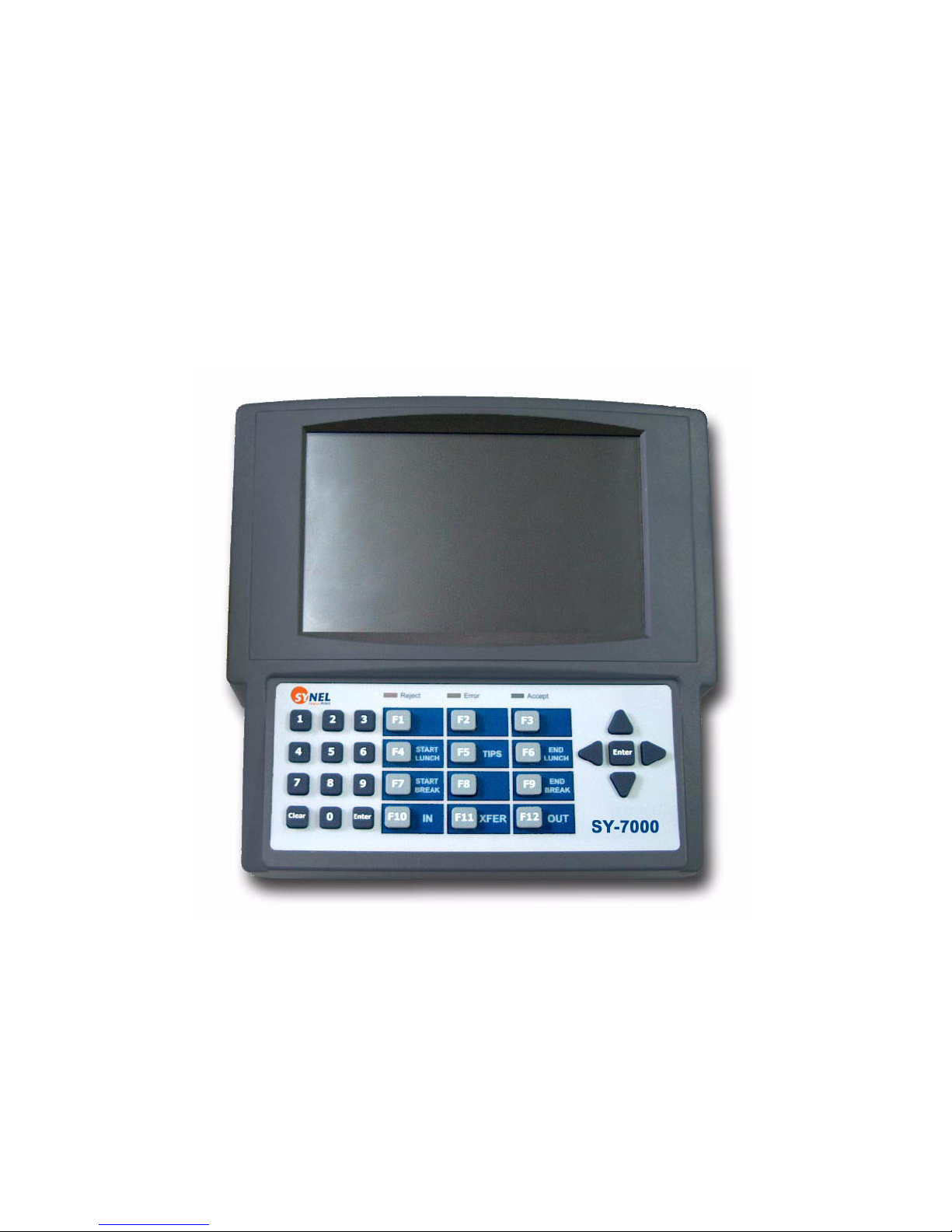
The SY-7000 series data collection terminal is introduced by Synel as a top of the line hardware terminal.
The terminal has almost unlimited capabilities when partnered with Synel’s additional time and attendance
software and hardware products. By using one or more of several different input methods, the SY-7000
series terminal records the time, date, employee number, and other collected data to be processed by a host
computer. The SY-7000 series data terminal has the capability to accommodate auxiliary inputs and
outputs used to control a wide variety of systems ranging from door access control to bells and alarms.
Each SY-7000 series terminal model type includes slightly different features. This guide is a compatible
and reliable installation guide for each type of terminal, regardless of the model type.
SY-7000 is an Open architecture terminal which enables the user to create their own settings and uses for
the terminal. The unit user defined capabilities are user-created using the Linux open source platform.
This SDK manual provides you with the information needed to create your own user defined system to
collect and manage Time and Attendance data.
1.1 SY-7000 Capabilities
In an effort to broaden availability and functionality of customer use, Synel offers several different model
types of the SY-7000 series data terminals. Each model type (7100, 7200, and 7500) differs slightly in
features ranging from wireless communications capabilities to LCD interactive touch screen menus. Please
refer to the Model matrix at the end of the book and the sales spec sheet for individual attributes.
1.1.1 TA 7100, 7200 & 7500 Family Specification
1.1.1.1Memory
TA 7100 & 7200
•8 MB SDRAM
• 16 MB Flash
TA 7500
•64 MB SDRAM
• 16 MB Flash
1.1.1.2Communications
•Ethernet
•Standard
• Support for 10/100 Mb networks
• Poe - Power for the unit enters from the same cable as your Ethernet
• Wireless
•RS-232
•RS-485
•Modem
• 1200 Kb – 28.8 Kb
5
Page 6

IntroductionSY-7000 SDK Manual
•2 USB ports
• –Host and Device
• –Bar-code wands
• –Printers
• –Keyboards
• 2 PCMICA Slots
• –Additional memory
•–Wireless
•802.11b
–WEP
–eap-leap wireless security
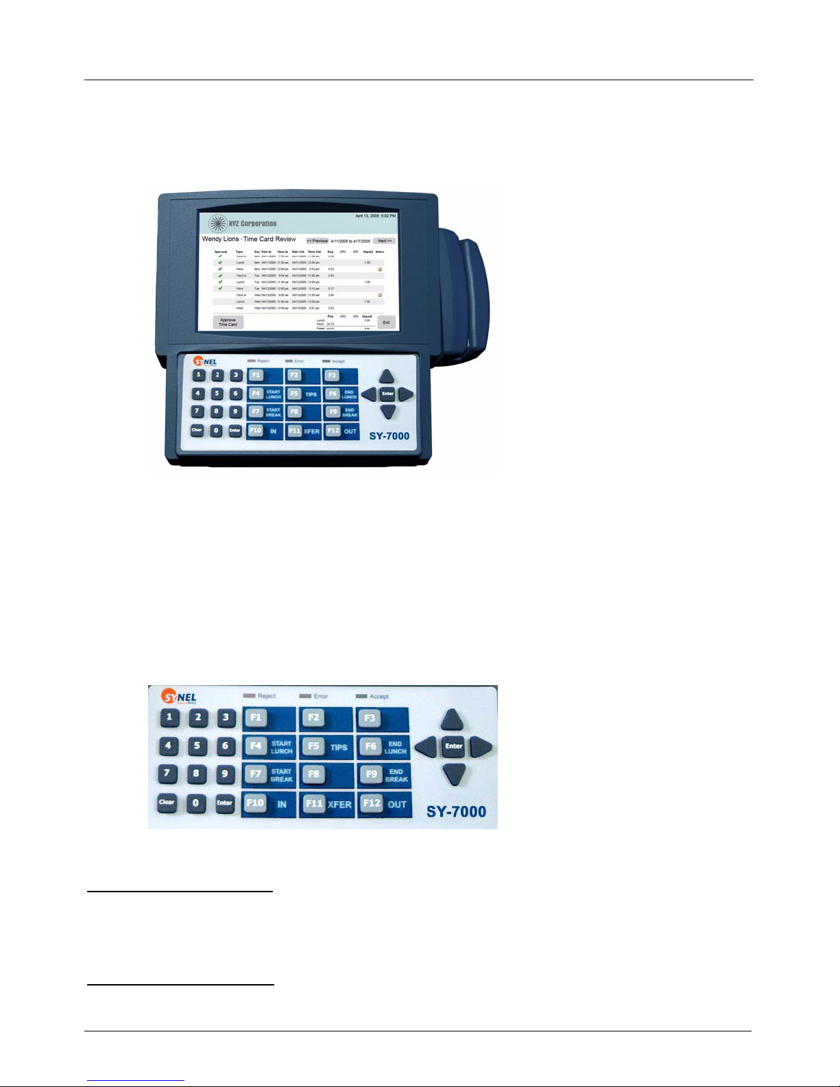
1.1.1.3LCDs
TA 7100 & TA 7200
• Large Character 4x20 backlit text display (6.5”)
TA 7500
• 8.0” Graphical color LCD touch screen
1.1.1.4Readers
• FPU- Finger Print Unit
• FPU-S (Capacitance) sensor
• Template size 384 Bytes (reducible to 256 bytes)
• Template capacity 9,000 at 4MB flash
• Encryption 256 bit AES (fingerprint data protection)
• Resolution 500 (dpi)
• Image size 280 x 320 (pixel)
• Bar Code and Key Entry
• Can have both bar code and magnetic on one reader
6
Page 7
SY-7000 SDK Manual Introduction
• Supports the following bar code formats: Code 39, Code 128, Interleaved 2 of 5, Industrial 2 of 5,
Codabar, UPC-A, UPC-E, EAN-13, EAN-8, UPC/EAN 2 & 5 digit AddOn, Code 11, Code 93, MSI/
Plessey, Code 4, Code 5 and BC412
• Internal Proximity Reader
The Proximity reader receives input via a two wire Wiegand type logic level interface consisting of a
pair of data lines Data0 and Data1. Data input via this interface is typically a small stream of from 26 to
36 bits representing a binary ID number that is broken into two or more fields in the software. Some
custom adaptations of this interface use longer bit streams of up to 60 plus bits.
1.1.1.5Rubber Keypad
• Numeric + 12 function keys + directional arrows
• Customizable overlay
1.1.1.6 Power Requirements
DC Power Input (@ J15):
15 VDC nominal; -1% - +7% (1)
0.25 - 1.5 A @ 15 VDC (2)
3.75 - 22.5 Watts (2)
AC Power Module(3) Input:
7
Page 8

IntroductionSY-7000 SDK Manual
90 - 264 VAC
47 - 63 Hz, single phase
0.5 A max. @ 90 VAC
5 - 23 Watts (2)
Power-over-Ethernet Input (via J4):
IEEE 802.3af compliant power sources only (4)
4 - 12.5 Watts (2)
• A wider DC input range is permissible depending on model and options configured; consult the factory
for details.
• Actual input power and current vary depending on model and options configured.
• Based on use of either of the following approved external AC to DC power modules:
Ault PW118RA1503F01
Sunny SYS1089-1515-W3
• Recommended stand-alone PoE power injector module:
Ault PW130RB4800F01
Note: PW130RA modules are not 802.3af compliant.
You can view the SY-7000 series matrix in “Model Matrix” on page 44.
1.1.2 The Software Development Kit
1.1.2.1Components
The following components are included in the SY-7000 SDK kit.
• The SY-7000 Terminal
(contains standard application named SY-7000)
• SY-7000 SDK disk (includes readme.txt file)
• Cross Compiler – GCC Version 3.3.3
•Cables
• Crossover Cable
• DB9 Cable (In Cables)
• SDK manual
• Terminal installation manual
1.1.3 Developer Minimum Skill Set
In order to assure the most efficient use of time and resources during while building the project, it is
important for developers to be proficient in at least the following minimum skill sets:
•C or C++
• Familiar with Linux
• Familiar with embedded systems
8
Page 9

SY-7000 SDK Manual Introduction
1.1.3.1Technical Specifications
The heart of the Terminal is based on a MPC885 from Freescale Semiconductor.
It is specifically designed to enable working with for several communication types and is powerful enough
to meet several future demands.
Operating System - standard open source embedded Linux Version 2.4.26.
9
Page 10
IntroductionSY-7000 SDK Manual
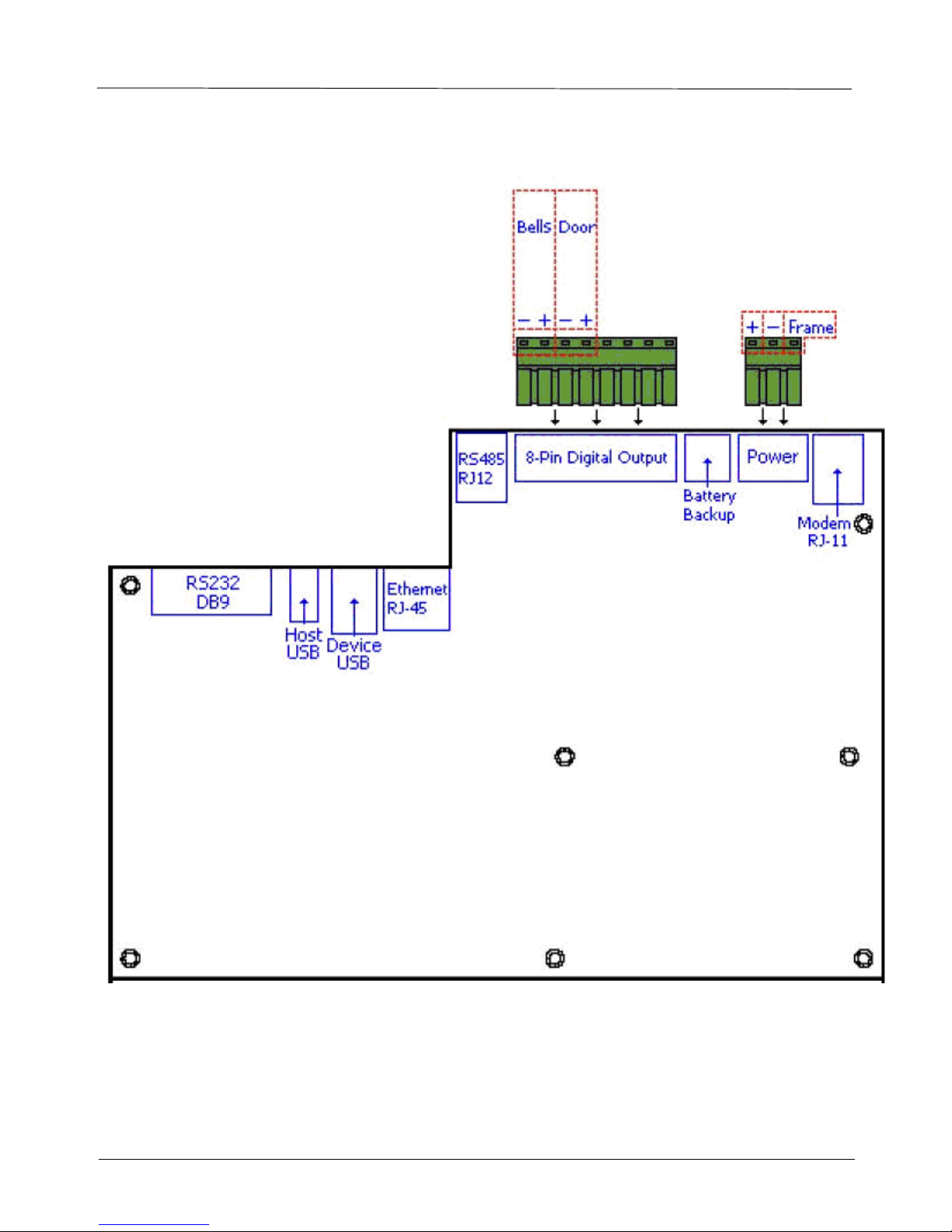
1.1.3.2Bottom connector panel
10
Page 11

SY-7000 SDK Manual Terminal Configuration Instructions
Chapter 2 -Terminal Configuration Instructions
The following section describes the way in which to initially configure the terminal, using the standard
configuration of the factory default SY-7000 application.
Most of the configuration can be done using the standard Linux system commands via Telnet or Serial
port, as explained in Communication Between the Host and Terminal on page 16.
2.0.1 Configuration Menu
The terminal is configured using the configuration menu.The configuration menu contains a variety of sub
menus, all of which have their own distinct functions. The default keypad code for accessing the
configuration menu is “00000”.
Below is a sitemap of the configuration menu (ver1.5 as of 03/06/2006):
Configuration
Dates
Set Date and Time
Daylight Savings
Communication
Wired
DHCP
Manually Config
TCP\IP Address
Gateway Address
Subnet Mask
Terminal ID
Wireless
SSID
Security
IP Settings
DHCP
Manually Config
TCP\IP Address
Gateway Address
Subnet Mask
Terminal ID
Set Readers
N/A
Accessory Test
Wireless Security
WEP
64 Bit
128 Bit
N/A
Clock Reset
Reset Clock
Clock Info
11
Page 12

Terminal Configuration InstructionsSY-7000 SDK Manual
Version
Application Version
Release Version
Root FS Version
Kernal Version
Wired Settings
Wireless Settings
Config Access
Keypad
Utilities
Telnet
2.0.2 Dates
The date configuration menu allow the programming of the terminal date and time, as well as configuring
the use of daylight savings.
2.0.2.1Set Date and Time
Once this option has been selected, the terminal will prompt for a date input. The date format is always
(MMDDYYYY). Once the date has been entered, the terminal will prompt for time entry. The time format
is always military time (HH:MM).
2.0.2.2Daylight Savings
When daylight savings is selected, the terminal will prompt for the use of daylight savings. The dates set
for daylight savings are standard and can be changed.
2.0.3 Communication
The communication menu is where the terminal is configured for the different types of communication:
Wired and Wireless.
2.0.3.1Wired
Wired communication indicates the presence of physical wires connecting the terminal to a computer.
Currently the terminal only defaults to TCP/IP communication across a network. There are two options
when selecting TCP/IP communication:
2.0.3.1.1DHCP (dynamic host configuration protocol)
Selecting DHCP will prompt the terminal to automatically select and configure its own network settings.
These settings can later be verified under the Clock Info menu.
2.0.3.1.2Manually Config
The manual configuration menu allows users to configure the network settings according to their own
specifications.
TCP/IP Address / Gateway Address / Subnet Mask
Using standard network format of 000.000.000.000, input an IP address. The arrow keys can be used to
scroll between the numbers.
12
Page 13

SY-7000 SDK Manual Terminal Configuration Instructions
Terminal ID
The terminal ID is set to identify the terminal in a LAN environment. The default is set to 1.
2.0.3.2Wireless
Wireless communication is done with a single or dual channel antenna pointed to a wireless access point.
The wireless network must be configured with an IP address, gateway, subnet, and WEP key (if available).
There are currently more additional menus when configuring the wireless.
2.0.3.2.1SSID (service set identifier)
After selecting SSID from the menu, the terminal will prompt for SSID entry. The SSID can be up to 20
characters long.
2.0.3.2.2Security
The SY-7000 series terminals come with the option of configuring security via WEP key solutions.
None
This will disable any wireless security.
WEP (wired equivalent privacy)
Selecting WEP for security will prompt for the entry of either a 64 bit, or 128 bit WEP key. After selecting
the WEP key type, the terminal will prompt for entry.
2.0.3.2.3IP Settings
The IP settings menu leads to the configuration of the network settings for the wireless card.
2.0.3.2.4DHCP (dynamic host configuration protocol)
Selecting DHCP will prompt the terminal to automatically select and configure its own network settings.
These settings can later be verified under the Clock Info menu.
2.0.3.2.5Manually Config
The manual configuration menu allows users to configure the network settings according to their own
specifications.
TCP/IP Address / Gateway Address / Subnet Mask
Using standard network format of 000.000.000.000, input an IP address. The arrow keys can be used to
scroll between the numbers.
Terminal ID
The terminal ID is set to identify the terminal in a LAN environment. The default is set to 1.
2.0.4 Set Readers
This feature is reserved for future application.
2.0.5 Accessory Test
This feature is reserved for future application.
13
Page 14

Terminal Configuration InstructionsSY-7000 SDK Manual
2.0.6 Clock Reset
Accessing the clock reset menu gives the option of resetting the terminal.
Warning! Resetting the terminal will erase all memory from the clock
defaults. This includes both the clock configuration, as well as the transactions.
, and restore it to the factory
2.0.6.1Reset Clock
The terminal will ask yes or no on the confirmation of being reset. After being reset, the terminal will
reboot and will display the default idle prompt.
2.0.7 Clock Info
The clock information menu can be accessed to display additional information about the terminal.
2.0.7.1Version
This menu displays the current version of the terminal.
Application Version (1.5 as of 03/06/2006)
Release Version (FlashFS: 2.1.5 as of 02/02/2006)
Root FS Version (RootFS: 2.0.3 as of 02/02/2006)
Kernel Version (Linux version 2.4.26-NE7200, Gcc version 3.3.3)
2.0.7.2Wired Settings
The wired settings menu re-displays the information that was configured when setting up the
communication. If DHCP was selected, this menu shows what settings the terminal automatically
obtained.
2.0.7.2.1IP Settings
This menu displays the IP address settings in the current format:
IP=000.000.000.000
NM=000.000.000.000
Gateway=000.000.000
2.0.7.2.2Network Status
The network status displays the live network status of transmitting data, which includes errors. The arrow
keys can be used to browse horizontally, should the information be scrolled off of the screen. The format
is:
RX bytes: (byte value) Errors: (byte value)
TX bytes: (byte value) Errors: (byte value)
2.0.7.2.3Mac Address
The TCP/IP MAC address which applies to the Ethernet wired network, displayed in the following format:
00:00:00:00:00:00
2.0.7.2.4Wireless Settings
The wireless settings menu re-displays the information that was configured when setting up the
communication. If DHCP was selected during the set up process, that information will be displayed here.
14
Page 15

SY-7000 SDK Manual Terminal Configuration Instructions
2.0.7.2.5IP Settings
This menu displays the wireless IP address settings in the current format: IP=000.000.000.000
NM=000.000.000.000 Gateway=000.000.000.000
2.0.7.2.6Wireless Status
The wireless status menu displays a live network of transmitting data, including errors over the wireless
network in the following format:
RX bytes: (bytes) Errors: (bytes)
TX bytes: (bytes) Errors: (bytes)
Link=% Signal=(Xlnt) Noise=-0dBm
(These options display the link and signal strength, as well as wireless noise. The signal is displayed as
“Xlnt” as it approaches closer to zero, which becomes a better connection.)
2.0.7.2.7Wireless Mac Address
The wireless MAC address which applies to the wireless device network, displayed in the following
format:
00:00:00:00:00:00
2.0.8 Configure Access
The access configuration menu allows the terminal to be configured for what acceptable methods are
available for accessing the clock configuration menu. Note that if the badge length changes, so must the
access configuration. The default for entering the configuration menu is “00000”. If the badge length is
changed, the configuration code will change by either adding or removing a subsequent character.
Warning! If the access code is changed and later forgotten,
nal will need to be sent back to the factory for repair, and have the original programming
restored. When selecting an access code, select something and write it down to prevent being
locked out from the terminal.
Example:
Default code is “00000”
Code is changed to “12345”
Badge length is changed to 6 (in software)
By default, code is changed to “123450”
there is no way to retrieve it. The termi-
2.0.9 Utilities
This menu displays a variety of utilities available with the TA7000 series terminals.
2.0.9.1Telnet Utilities
The Telnet utilities are used for enabling or disabling Telnet.
2.0.9.1.1Enable Telnet
Enables the Telnet utility.
2.0.9.1.2Disable Telnet
Disables the Telnet utility.
15
Page 16

Application Development InstructionsSY-7000 SDK Manual
Chapter 3 -Application Development Instructions
You can add almost unlimited capabilities to the SY-7000 terminal by writing your own terminal
applications. The following section describes the way in which to develop your own customized
application for the SY-7000 terminal.
3.1 Toolchain Development Tools
This sections lists the tools needed to compile and link the application used for developing an application
for SY-7000.
3.1.1 CygWin
CygWin is a collection of free software tools which allow various versions of Mcrosoft Windows to act
similarly to a Unix system. This aims mainly at porting software that runs on POSIX systems (such as
Linux, BSD, and Unix systems) to run on Windows. For information about how to download and use
Cygwin see Setting Up the PIK Environment on page 38.
3.1.2 Cross Compiler
Cross Compiler is provided in the SY-7000 SDK kit in a tar file called tools.2006-12-15.tar.gz).
Step 1. Extract the cross compiler by opening the CygWin window and typing “cd /” and a command
such as the one below, for a file residing in the C:/CrossCompiler directory.
tar –xzf /cygdrive/c/CrosCompiler/ tools.2006-12-15.tar.gz
Note: If your TAR file resides in a location different than C:/CrossCompiler edit the command to
match the file location.
Step 2. After extracting the Cross Compiler, add the path C:\cygwin\tools\bin to the Path variable
environment.
3.1.3 FTP or TFTP Server
An FTP or TFTP server is needed to upload the application from the host to the terminal. The FTP or
TFTP server must be available in the host and must indicate the directory where the application exists.
3.2 Communication Between the Host and Terminal
Communication between host and terminal can be done either by Serial port or via Telnet. The
communication in both ways is described below.
3.2.1 Setting up Communication by a Serial Port
Step 3. Physically connect between the host and the terminal with a Serial port cable.
Step 4. Open a communication program such as HyperTerminal (in Windows XP open via Start/
Programs/ Accessories/ HyperTerminal)
Step 5. Enter the following details to set the connection:
Bits per second = 38400 (baud rate)
Data bits = 8
Parity = None
16
Page 17

Application Development InstructionsSY-7000 SDK Manual
Stop bits = 1
Flow control = None.
Step 6. When the communication is defined, select File/ Open.
The terminal comes up and the terminal data is displayed.
The last line which appears should resemble: “192.168.108.2 login:” (the IP may vary according
to what is entered in the UBoot)
Step 7. After this last line appears type “root” and press ENTER.
Step 8. When a # symbol appears on the command line type the command “cd /” to go to the file system
root directory.
From the root directory you can drill down to the Terminal directory (under Home/Terminal)
where you can upload your application to the terminal.
3.2.2 Setting up Communication via Telnet
PREREQUISIT - Before connecting to the terminal via Telnet you need to set a legal IP in the local
network. See Chapter 2 - Terminal Configuration Instructions for information on how to set an IP for the
terminal.
The recommended IP for the terminal is: 10.0.0.2
Step 1. Physically connect between the host and the terminal to a network connection cable.
Step 2. Open the Command prompt in the host (by opening Start/ Run, typing “cmd” and press
ENTER).
Step 3. Type the command: “telnet 10.0.0.2” and press ENTER.
The terminal comes up and the terminal data is displayed.
The last line which appears should resemble: “192.168.108.2 login:” (the IP may vary according
to what is entered in the UBoot)
Step 4. After this last line appears type “root” and press ENTER.
Step 5. When a # symbol appears on the command line type the command “cd /” to go to the file system
root directory.
From the root directory you can drill down to the Terminal directory (under Home/Terminal)
where you can upload your application to the terminal.
17
Page 18

SY-7000 SDK Manual Writing the SDK Application
Chapter 4 - Writing the SDK Application
The SY7000 SDK runs give the user the ability to develop an C++/C application which accesses and
control the S Y7000 functionality terminal like (Keyboard, LEDs, card readers, Buzzer, Relay).
The SDK is based on the following libraries that are supplied in the CD:
GLibC – GNU C Library
The C language provides build-in facilities for performing such common operations as input/output,
memory management, string manipulation and the like. The GNU C library core is an ANSI/ISO standard
C library. GNU C also includes extension compatibility with Posix, BSD, SUID, and XPG.
Interface Library
Simple and easy to use, the interface library is event driven and multi-threaded. The user application can
be a single threaded program. The simplicity of the interface library removes the complexity of file and
event I/O and also removes the need for low level hardware interfacing.
LibNE7000Pik – is the high level library, written in C++. The purpose of this library is to extend the low
level library and give it the ability to manage and control events, and terminal functionality using a simple
API.
The classes of this library are described below.
LibNE – is the low level library written in C. This library is closer to the hardware and the user rarely
needs to access the functions of this library because it is extended by the high level functionality of
LibNE7000Pik.
18
Page 19

Writing the SDK ApplicationSY-7000 SDK Manual
CLASS EVENTMANAGER
This class is responsible to handling all events in the system the Event Manager related to 8 events.
Every event has a call back function that presents the handle function. When one event occurs the call
back function for this event is called and in this way you can configure the functionality of every event.
The events are:
• Keyboard
• Magnetic card track 1
• Magnetic card track 2
• Magnetic card track 3
• Barcode card
• Proximity card
• Timer
• Proximity
Public methods:
• virtual ~EventManager();
• void RegisterForEvent(Event eventId, EventCallback callback, void* userdata);
• void UnRegisterForEvent(Event eventId, EventCallback callback);
• int InstallNetworkServer (const unsigned int port , const char* ifc = "eth0" );
• int createLowResTimer (long timeoutSeconds);
• void killTimer (int timerId);
• int EventLoop ();
• static EventManager * GetInstance();
Methods description:
virtual ~EventManager();
This is the destructor for EventManager
void RegisterForEvent(Event eventId, EventCallback callback , void* userdata );
This is used to register a callback for an event
Arguments:
Event eventId
event we are registering for. The available events include:
• EVENT_KEYBOARD,
• EVENT_BARCODE,
• EVENT_MAGCARD1,
19
Page 20

SY-7000 SDK Manual Writing the SDK Application
• EVENT_MAGCARD2,
• EVENT_MAGCARD3,
• EVENT_PROXCARD,
• EVENT_TIMER,
• EVENT_SOCKET
EventCallback callback
function to be called when the event occurs
void* userdata
pointer to structure passed when the event triggers callback
The callback function used must be in the following the form:
void _callback_keys (Event event
const char * data_p
const unsigned int size
,
,
void * userdata_p)
where the values passed are as follows:
event
registration event, as defined above
data_p
specific data for each callback as follows:
keyboard
value of key pressed
card (all cards)
card value
timer
timer_id, as returned by createLowResTimer (see below)
socket
socket data
userdata_p
,
value passed to RegisterForEvent
void UnRegisterForEvent(Event eventId, EventCallback callback);
Unregister the event:
Event eventId
event being unregistered from (card, keyboard, timer, etc.)
EventCallback callback
function to be called when event occurs
20
Page 21

Writing the SDK ApplicationSY-7000 SDK Manual
int InstallNetworkServer ( const unsigned int port , const char* ifc = "eth0" );
Installs a network server. InstallNetworkServer should not be called more than once!
Arguments:
port
port for session
ifc
interface (default "eth0")
int createLowResTimer (long timeoutSeconds);
Creates a timer
Arguments:
// create a timer
resolution in seconds
Returns:
Timerid
id of timer created
void killTimer (int timerId);
// kill a timer
Arguments:
timerid
as returned by createlowrestimer
int EventLoop ();
// main event loop
wait here for events till “done” flag raised
static EventManager * GetInstance();
Get the instance of the event manager. If none exists, create one.
21
Page 22

SY-7000 SDK Manual Writing the SDK Application
CLASS LCDDISPLAY
The LCDDisplay class is responsible for handling the LCD display (4 rows x 20 columns).
Public methods:
• LCDDisplay ();
• virtual ~LCDDisplay ();
• virtual void Write (int row, int col, const char * str);
• virtual void Clear ();
• virtual void DisplayContrast(int contrast);
• virtual void SetCursorState (CursorState state);
Methods description:
LCDDisplay ();
This is the constructor for the LCDDisplay class responsible for initializing the display. It should be
called only once per application.
virtual ~LCDDisplay ();
This is the destructor for the LCDDisplay class.
virtual void Write (int row, int col, const char * str);
Write the supplied string to the LCD display. Printable ASCII characters are displayed; certain control
characters cause their normal display actions (see Notes below).
Arguments:
row
position of the specified row before writing (starting from 1);
0
use current row setting.
col
position of the specified column before writing (starting from 1);
0
use current column setting.
Str
string to write to display (see notes).
Notes:
The LCD Write command optionally positions the cursor and then writes data to successive display
positions. The data consists of a pair of cursor position bytes followed, optionally, by data to write to
22
Page 23

Writing the SDK ApplicationSY-7000 SDK Manual
the display. The first position byte specifies the LCD character row while the second position byte
specifies the LCD character column. The rows and columns are numbered starting with 1.
A row or column position of 0 indicates the respective value does not change, instead the current cursor
row and/or column is used.
Any bytes following the two positioning bytes are written to the display as ASCII data starting at the
present cursor position as defined by the positioning bytes. If encountered, any of the 32 character
codes in the range 00h to 1Fh are not sent to the display. Some of the values in this range perform their
standard ASCII functions as follows:
• NewLine '\n' [0Ah] Position to column 1 of the next row.
• Carriage Return '\r' [0Dh] Position to column 1 of the current row.
• Form Feed '\f' [0Ch] Position to row 1, column 1.
Non-ASCII character codes in the range of 80h to FFh are sent to the display without further processing
and are assumed to be displayable characters. The resulting display is hardware dependent and left to
the Master Controller developer and driver for its specifics.
virtual void Clear ();
Clears the LCD display and sets the cursor at row 1, column 1
virtual void DisplayContrast (int contrast);
Sets the contrast of the display. The value of contrast varies between 0 (maximal contrast) and 0xffff
(minimal contrast).
virtual void SetCursorState (CursorState state);
Sets the cursor state to one of the options defined in CursorState.
CursorState can have one of the following values:
• CURSOR_OFF = 0, - no cursor
• CURSOR_UNDER, - cursor underneath the current position (displays a horizontal line)
• CURSOR_BLINK, - cursor blinking at current position
• CURSOR_BOTH - cursor has both line under and blinking
23
Page 24

SY-7000 SDK Manual Writing the SDK Application
CLASS SOUND
This class is responsible for creating sounds in the system.
Public methods:
• Sound();
• virtual ~Sound();
• void Beep(int milliseconds, int toneHz);
Methods description:
void Sound ();
Creator for the Sound class
virtual ~Sound();
This is the destructor for Sound class
void Beep(int milliseconds, int toneHz);
This method is used to create a sound
Arguments:
int milliseconds
duration of the sound, in milliseconds
int toneHz – tone of the sound, in Hertz
24
Page 25

Writing the SDK ApplicationSY-7000 SDK Manual
CLASS LED
This class is responsible for operating the LED in the system.
Public methods:
• LED();
• virtual ~LED();
• void TurnOn(Light light);
• void TurnOff(Light light);
Methods description:
void LED ();
Creator for the LED class
virtual ~LED();
This is the destructor for LED class
void TurnOn(Light light);
This method is used to turn the light on
Arguments:
Light light
color of light
The LED can emit one of the following colors:
LIGHT_RED = 1
LIGHT_YELLOW = 2
LIGHT_GREEN = 3
25
Page 26

SY-7000 SDK Manual Writing the SDK Application
CLASS RELAY
This class is responsible to set output relay.
Public methods:
• Relay ();
• virtual ~ Relay ();
• void Set(int index, int state);
Methods description:
void Relay ();
Creator for the Relay class
virtual ~ Relay ();
This is the destructor for Relay class
void Set(int index, int state);
This method is used to set the state of the relay.
Arguments:
int index
index of the relay (value of 1-4)
int state – new state of the relay (0 – off, 1 – on)
26
Page 27

Writing the SDK ApplicationSY-7000 SDK Manual
4.1 Demo Application
The SY-7000 demo gives simple examples of how the various APIs can be used. The application first
initializes the system. This includes the following functionalities:
• Defining the IP address for TCP based applications (such as FTP).
• Registering callbacks for cards (barcode, magnetic or proximity).
• Registering callbacks for keys.
• Registering callbacks for timer events.
• Defining two different timers (one every second, the other every two minutes)
The application then waits in a busy loop for user interactions. The demo has the following modes:
• Initial mode - In this mode the initial screen is shown, and the user can choose to enter one of the
following modes:
• Simple op mode
• Offline mode
• Online mode.
In order to change the system state, the user should press the “Clear” button, in order to return to the
previous state, unless stated otherwise (i.e. if we have chosen Barcode mode, and want to change to the
Keyboard input mode, press Clear first).
Demo Program file types
The following files are used by the Demo program:
Employees.txt - Lists the information per employee, in the following format:
Card_ID Last_Name First_Name
A space is used as a delimiter between fields.
The Card_ID is a 6 character string.
Department.txt - Lists the department ID and name, in the following format:
Department_ID Department_Name
A space is used as a delimiter between fields.
Transactions.txt - Lists the transactions performed by employees (IN, OUT, etc.), in chronological
order, in the following format:
Transaction_ID Employee_ID Time
A space is used as a delimiter between fields.
The time format is as defined by the ctime function with 28 characters. (Wed Jan 02 02:03:55
1980\n\0).
These files are stored in the directory defined for the user in the FTP server (currently ftproot).
Following is a list of the options for each mode:
27
Page 28

SY-7000 SDK Manual Writing the SDK Application
4.1.0.0.1 Simple operations application
• Magnetic card reader
• Barcode wand
• Proximity reader
• Keyboard Input & Navigation
• Fingerprint reader operation
• FTP communication
• Play buzzer/sounder
• Relay outputs
• Display contrast adjust
F1 – Magnetic card reader
• Displays – “Swipe a magnetic card”
• Waits for magnetic card input (other inputs will be ignored)
• Displays Magnetic card number
F2 – Barcode card reader
• Displays – “Swipe a barcode card”
• Waits for Barcode input (other inputs will be ignored)
• Displays Barcode number
F3 – Proximity card reader
• Displays – “Swipe a proximity card”
• Wait for proximity card input (other inputs will be ignored)
• Displays proximity number
F4 – Keyboard input
• Displays – “Key in # using 0123456789"
• Waits for data from KB
• Displays the keyboard input until Clear is entered.
F5 – Navigation keys
• Displays – “Use the scroll keys to move the *”
• Set the * at the middle of the screen
• Waits for navigation keys
• Moves the * according the key.
28
Page 29

Writing the SDK ApplicationSY-7000 SDK Manual
F6 – Finger print reader
• Display – “Finger print “
• Display – “1- Enrol 2- Verify 3 – Identify”
• Wait for Input from KB
Enroll
• Display “Key in your ID”
• Wait for ID
• Display “Put your finger on sensor”
• Wait for score
• Display score
Verify
• Display “Key in your ID”
• Wait for ID
• Display “Put your finger on sensor”
• Wait for result
• Display score
Identify
• Display “Put your finger on sensor”
• Wait for result
• Display score & ID
iF7 – Date & Time buffer
• Displays “Current date and time”
• The date and time are updated every second
Note: In this mode a one second resolution timer is created and used to display the updated time, and
the timer killed when we exit date and time mode. This is used in order to show how a timer can
be created during the application and not only during installation (another option would be to
use the one second timer already existing in the system).
F8 – Activate buzzer
• Displays “Buzzer operation”
• Uses F1-F12 to play 12 notes of scale.
• Uses Clear key to end.
Each note is played for a second duration.
F9 – Activate relay
• Displays “Relay Operation”
• Uses F1,F4,F7,F10 to turn ON outputs 1-4 respectively.
29
Page 30

SY-7000 SDK Manual Writing the SDK Application
• Uses F2,F5,F8,F11 to turn OFF outputs 1-4 respectively.
• Uses F3,F6,F9,F12 to alternate output 1-4 every 1 second for 10 seconds.
• Uses Clear to exit.
F10 – Put a file via FTP
• Displays – host File name
• Puts the file, display each operation
• Displays number of bytes transferred, if transfer successful, or error message otherwise
Note: An FTP server must be active in the host computer (as defined by the IP address given during
initialisation.
F11 – Get a file via FTP
• Display – host File name
• Get the file, display each operation
• Display number of bytes transferred, if transfer successful, or error message otherwise
Note: An FTP server must be active in the host computer (as defined by the IP address given during
initialization.
F12 – Adjust Display Contrast
• Displays “Use up & down Arrows to adjust contrast.”
• Adjusts the screen contrast in 16 steps.
• If “Enter” is pressed this saves the new contrast setting to boot loader environment settings for use on
reboot. If “Clear” is pressed the new setting is kept, but not stored in the boot loader.
4.1.0.0.2 Typical OFF Line application
• Magnetic card reader
• Employees file - Valid card numbers + Name
• Departments file – Department ID + Name
Communication with host
• Uses FTP once a day to update employees and department file from a host
• Uses FTP every 2 minutes to transfer the transactions.
F1 – IN
• Displays–“IN – Swipe your card”
• Waist for card
• Displays Employee name – or error message if name is not found
• Saves a record to a file (“Transact.txt”)
• The name will be removed after “Clear” is pressed – or after 5 seconds.
30
Page 31

Writing the SDK ApplicationSY-7000 SDK Manual
F2 – Out
• Display – “OUT – Swipe your card”
• Wait for card
• Display Employee name – or error message if name is not found
• Saves a record to a file (“Transact.txt”)
• The name will be removed after “Clear” is pressed – or after 5 seconds.
F-2 – In on Duty
• Display – “IN on Duty – Swipe your card”
• Wait for card
• Display Employee name – or error message if name is not found
• Saves a record to a file (“Transact.txt”)
• The name will be removed after “Clear” is pressed – or after 5 seconds.
F-3 – Out on Duty
• Display – “Out on Duty – Swipe your card”
• Wait for card
• Display Employee name – or error message if name is not found
• Saves a record to a file (“Transact.txt”)
• The name will be removed after “Clear” is pressed – or after 5 seconds.
F-5 – Department transfer
• Display – “Department transfer – Swipe your card”
• Wait for card
• Display Employee name second row – or error message if name is not found
• Display first department on third row
• Use scroll keys to choose the department (as defined in file “Department.txt”).
• Saves a record to a file (“Transact.txt”)
• The name will be removed after “Clear” is pressed – or after 5 seconds.
F-6 – Start a Job
• Display – “Start Job – Swipe your card”
• Wait for card
• Display Employee name on second row – or error message if name is not found
• Display “Key Job number”
• Wait for input from KB until “Enter” pressed
• Saves a record to a file (“Transact.txt”) – if “Enter” pressed
31
Page 32

SY-7000 SDK Manual Writing the SDK Application
• The name will be removed after “Clear” is pressed – or after 5 seconds.
4.1.0.0.3Typical ON Line application
• Barcode reader
F1 – ON line query
• Display – “IN – Swipe your card”
• Wait for card
• Send the card to host over TCP
• Display Result to Employee – or error message if name is not found, or communication fails
• Saves a record
32
Page 33

Writing the SDK ApplicationSY-7000 SDK Manual
33
Page 34

SY-7000 SDK Manual Creating and Loading the Application File to the Terminal
Chapter 5 - Creating and Loading the Application File
to the Terminal
This chapter describes the way in which to create a binary file of the application you have written for the
terminal and the way in which to load the application to the terminal.
5.1 Creating a Binary File of the Application
In order to run your application on the terminal you need to make it into a binary file.
To create a binary file of the application, that can be run in the terminal use the GNU Compiler Collection
(GCC) of the Power PC Core that is provided in the SDK CD.
Step 1. Open the GNU Compiler Collection (GCC) that is provided in the SDK CD.
Step 2. Enter a command as in the example below to create the binary file:
powerpc-88x-linux-gnu-gcc application_name –o binary_file_name
For example:
powerpc-88x-linux-gnu-gcc NE7200.c –o NE7200
Step 3. In the terminal run the command by typing: ./binary_file_name
For example: ./NE7200
For help of how to use the Power PC GCC type: powerpc-88x-linux-gnu-gcc –help
For a demo application example containing a make file, for viewing additional options of using the
Power PC GCC see the make file in the demo application.
All of the commands for the Power PC GCC can be found in the directory c:/cygwin/tools/bin.
Add this path to the Windows Environment variables for viewing.
34
Page 35

Creating and Loading the Application File to the TerminalSY-7000 SDK Manual
5.2 Loading the Application Binary file to the Terminal
Writing to the terminal file system is only allowed in the Home directory and Terminal subdirectory, all
other directories of the terminal file system are read only.
The “chmod” command used here gives the terminal the permission to execute the application.
Following are the commands used to upload files to the terminal. These are provided in TPTP and FTP.
By TFTP:
cd /home/terminal/bin
tftp –g –r local_file –l remote_file remote_host
chmod +x remote_file
For example:
cd /home/terminal/bin
tftp –g –r NE7200 –l NE7200 10.0.0.2)
chmod +x NE7200
For help for using TFTP commands enter “tftp --help”.
By FTP:
cd /home/terminal/bin
ftpget remote_host remote_file local_file
chmod +x remote_file
For example:
cd /home/terminal/bin
ftpget 10.0.0.2 NE7200 NE7200
chmod +x NE7200
For help for using ftpget commands enter “ftpget --help”.
35
Page 36

SY-7000 SDK Manual Creating and Loading the Application File to the Terminal
5.3 Running The Application on Terminal Startup
You can set the terminal to run the application on startup.
To do this you need to edit the “applstart.sh” script in the /Home/Terminal directory.
The following commands are used to edit the script:
Step 1. Enter vi applstart.sh to begin editing the script.
Step 2. To begin editing press the “i” key on the keyboard.
Step 3. Move between the rows to edit, using the keyboard arrows.
Step 1. When you are finished editing press “Esc” to exit editing mode.
Step 2. Type “ZZ” to save and exit.
Edit the script to run the application at startup as follows:
APPL_DIR=application_path
APPL_NAME=application_name
APPL_ARGS=arguments
For example:
APPL_DIR=/home/terminal/bin
APPL_NAME=NE7200
APPL_ARGS=
36
Page 37

Creating and Loading the Application File to the TerminalSY-7000 SDK Manual
37
Page 38

SY-7000 SDK Manual
Appendix A - Setting Up the PIK Environment
This appendix describes the way in which to set up cygwin to set you Microsoft Windows platform to act
similarly to a Unix system. See “CygWin” on page 16 for additional information.
Step 1. Download Setup.exe from
http://www.cygwin.com
38
Page 39

SY-7000 SDK Manual
Step 2. Download the file and run the installation.
Step 3. When the download is complete, click Run.
The Cygwin setup opens.
Step 4. Click Next until you reach the screen displayed below.
Step 5. Select “Install from Internet” and click Next.
39
Page 40

SY-7000 SDK Manual
Step 6. Use the default settings on this screen and click Next.
40
Page 41

SY-7000 SDK Manual
Step 7. Specify the location to store the installation files and click Next.
41
Page 42

SY-7000 SDK Manual
Step 8. Select Direct Connection and click Next.
42
Page 43

SY-7000 SDK Manual
Step 9. Pick a mirror to download Cygwin from.
It is recommended to select a site that is local to your geographic area and click Next.
43
Page 44
SY-7000 SDK Manual
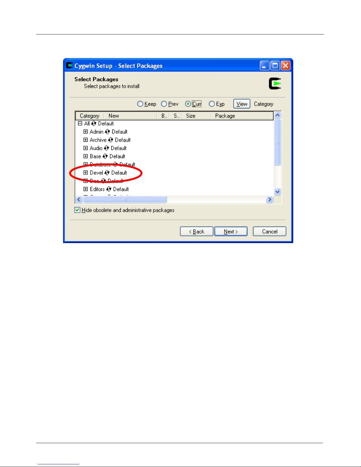
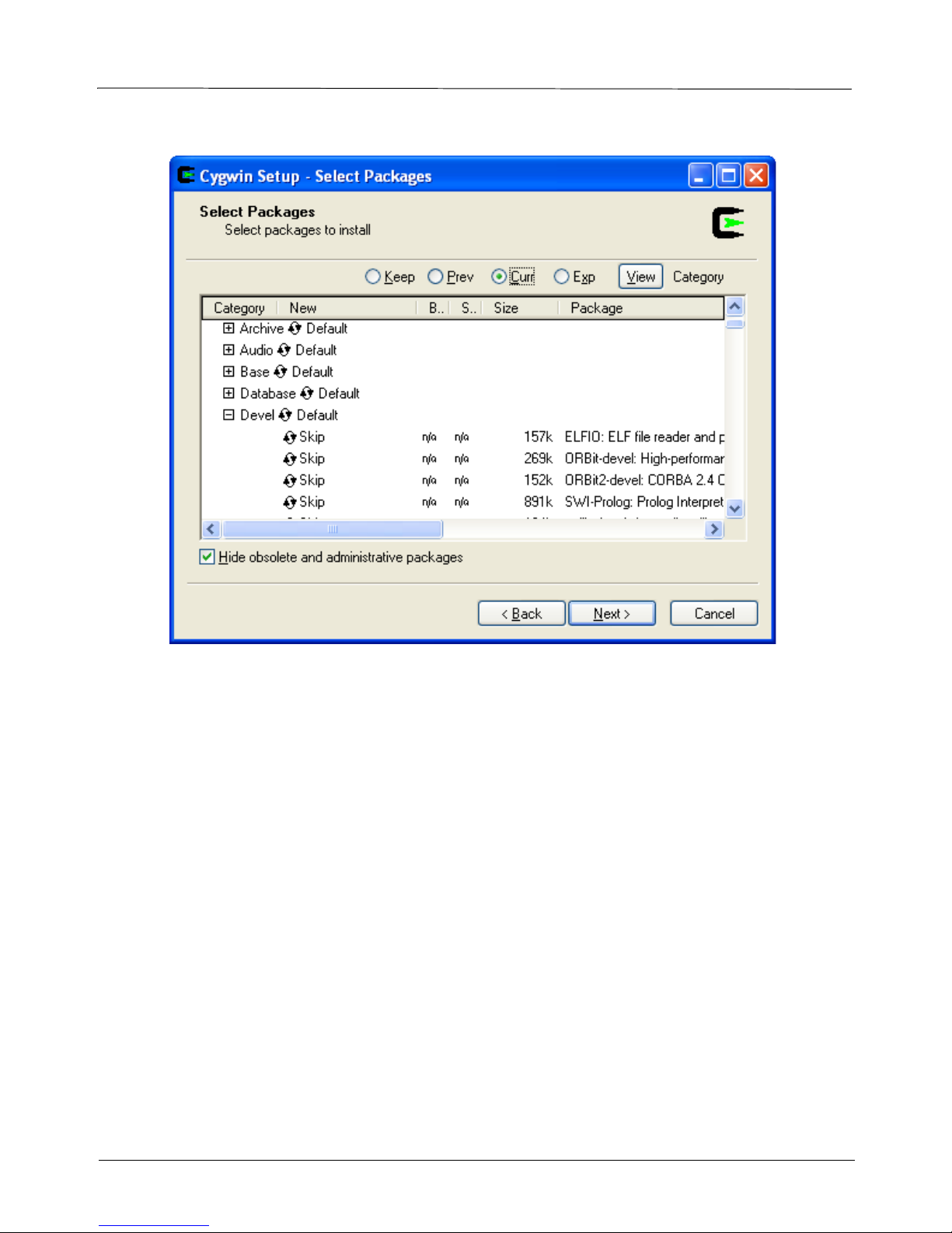
Step 10. Click the + sign next to Devel to expand it.
44
Page 45
SY-7000 SDK Manual
Step 11. Under Devel, scroll down to gcc.
45
Page 46
SY-7000 SDK Manual
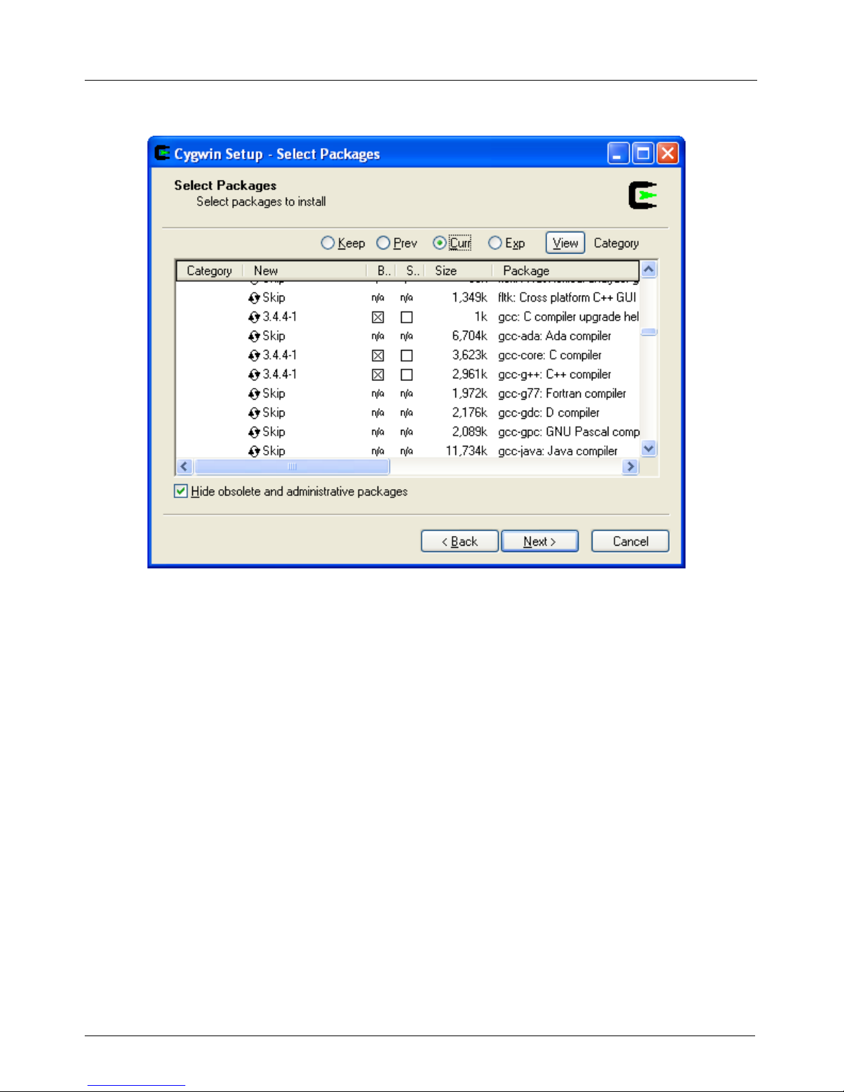
Step 12. Select gcc by clicking on the word Skip once.
46
Page 47

SY-7000 SDK Manual
Step 13. Scroll down and select the make and any other packages you want included and click Next.
47
Page 48

SY-7000 SDK Manual
Cygwin will now download and install the packages that you selected.
48
Page 49
SY-7000 SDK Manual
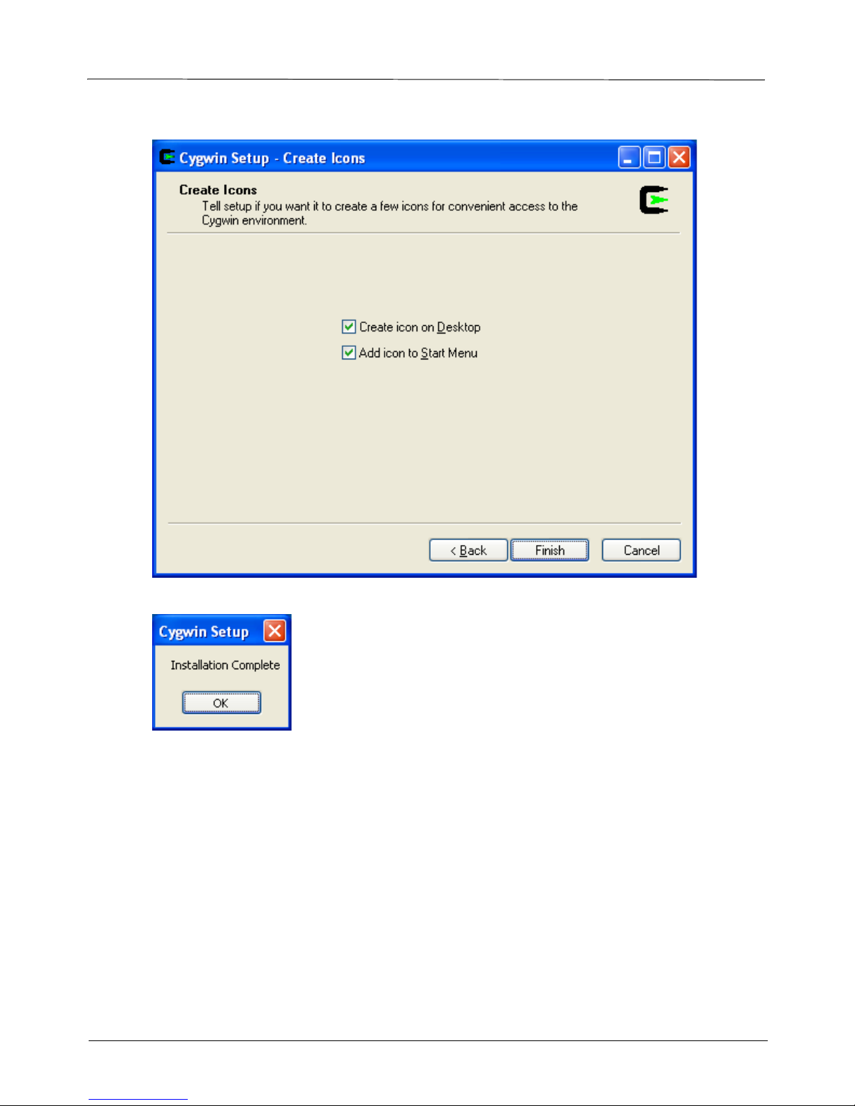
Step 14. Leave the options checked and click Finish.
49
Page 50

SY-7000 SDK Manual
Step 15. Copy file that was now created to the Cygwin root directory (you will need WinZip or similar
application installed for this).
Step 16. Run Cygwin.bat.
Step 17. Type in cd / and press ENTER.
You can now use Cygwin.
50
Page 51

SY-7000 SDK Manual
51
Page 52

SY-7000 SDK Manual
52
Page 53

SY-7000 SDK Manual
Appendix B - Model Matrix
Model TA7100 TA7200 TA7500 TA7700
Processor
Flash
SDRAM
10/100 Base-T
Wireless (802.11x) option
RS-232
RS-485
Modem option
USB
PCMCIA option
Mag. Card
Bar Code option
Wiegand option
Digital Out
Power over Ethernet option
Graphical LCD
External LCD
Proximity card
Add additional memory
External bar code wand option
External keyboard option
External printer option
Plug and Punch
Customizable overlay
MPC885 MPC885 MPC885 MPC885
16 MB 16 MB 64 MB 64 MB
8 MB 8 MB 16 MB 16 MB
44
Page 54

SY-7000 SDK Manual
45
 Loading...