

Page 1
SY-1001/01 SY-1001/01 SY-1001/01
General
Introduction
SY-10/xR is a magnetic, bar-code or proximity card reader
with a keyboard, and a transmitter. It pertains to the SY10
magnetic/barcode reader emulation series.
The SY-10/xR decodes the card and transmits the signal serially in RS-232 protocol (ASCII) in a range of up to 30m. The
data is transmitted only once.
When operated the unit immediately waits for host instructions
and is ready to decode a magnetic/barcode/proximity card as
per the installed reader.
This protocol enables improved management of reader, keyboard, leds - using a PC. It is based on Synel standard data collection protocol. To simplify the use of fields, instead of
calculating CRC fields, they can be replaced with “@”. The
commands to be implemented are:
Get DATA-The last data to be received will be sent.
Clear DATA-The buffer housing the data will be cleared.
Activate device-Operate one of the indicators (led, buzzer,
relay).
This command is used also for managing the card reader and
the keyboard.
The keyboard is managed internally. It can be used for inserting the pin code or for the identification number. Each keyedin character is automatically transmitted to the controller as per
reader type:
• In SY-10/MR - Magnetic track II ANSI standard
• In SY-10/PR - Magnetic track I ANSI standard
These are transmitted between two “:” characters to enable the
controller to close the data source.
• In SY-10/BR - Barcode, COD39.
• In SY-10/PRX/R -Proximity 125 KHz.
It is transmitted between two‘A’ characters.
The unit consists of a bi-color LED controlled internally.
Format of commands and replies
These commands enable the host to receive the last transmitt ed
transaction and activate the various devices (LED, buzzer,
relay). Command structure for this reader is a subset of SDCP
(Synel Data Collection Protocol) (For further information see
SYNEL protocol manual). Format changes are as follows:
1. CRC communication is not checked (@@@@ or
ignored)
2. Permanent ID = 0
3. The commands are as follows:
Standard SYNEL ACK & NACK commands, and:
W-Opcode setup:
Installation
The unit may be installed in any building. It can also be
mounted adjacent to any other reader of the same series PRX
or PRintX. Then the unit’s slips must be fastened to the neighboring unit’s notches. The back panel of the unit serves as a
handy installation template for installation. Mounting screws
and plugs are also provided. Following these guidelines:
1. The installation location selected should be as far as possible from sources of electrical reference such as power
equipment, computers, motors, pumps, etc.
2. A mounting template designated to describe units
assembly steps is attached for technician convenience.
Mounting base first
1. Open the back of the unit.
2. Press-to-break both mounting holes (See back panel
drawing) and the designated RJ45 hole.
3. Drill as per mounting template instruction.
4. Thread the cable RJ45 connection cable (See back panel
drawing) (option) or use the nock down option-mounting template instructions.
5. Mount the base to the wall using the long screws.
6. Close the cover unit using the designated notches and
the short screws (See front panel drawing).
7. Place stickers A+B as in the front panel drawing.
Command Description Reply
Getdata Retrieves data
(
B-Op code)
(d) = data – will send the last data in the
buffer
(n) = no data
Cleardata Deletes data
(
C Op code)
(Ack) – data will be deleted. If the PC
requests data again, the terminal will reply
“There is no data”. Unless, new data was
just received (via the KB or reader.
ActivateDevice Activate
device
(
W Op code)
This command is currently unavailable.
See structure in the page below!
Field Lgth Value Remarks
1. Op code 1 W
2. Mid 1 0-? @- Disregard this field
3. Operation 1 S- Set device = 1
P- Pulse
R- Reset device= 0
Ignor time fields
Ignor time fields
4. Device ID 2 01- Green led
02- Red led
03- Amber led
04-Card reader
08- Keyboard
10- Buzzer
20- Relay
Available for pulse operation
0 to 255 in 1/10 second
steps
(o to 25.5 seconds)
5. Set time 3 000-255 50 milliseconds
6. Reset time 3 000-255 50 milliseconds
7. Total time 3 000-255 50 milliseconds
8. CRC 4 @@@@- do not verify
9. EOT 1 CR or hex04
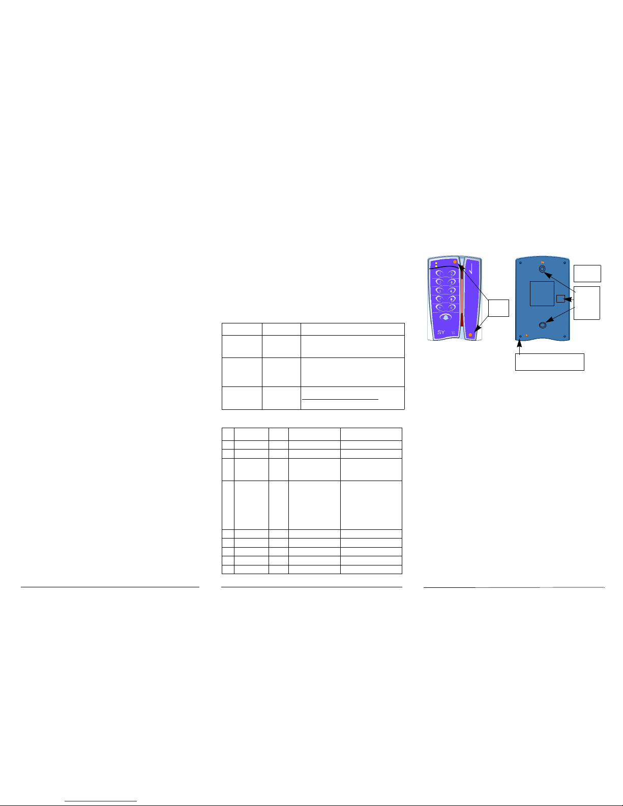
Mounting
holes
Either
RJ45/ or
Terminal
block
Cover
notches
Front panel
B
A
Back panel
Option B: Knock-down
notch communication cable
Page 2
SY-1001/01 SY-1001/01
SYNEL Industries LTD.
Y okn eam Industrial Park, 2 Hamada St.,
POB 142, Yokneam 20692, Israel
Tel: +972-4-959 6777 Fax: +972-4-959 0729
E-mail: info@synel.com
Jumper Setting for SY-10/xR
Connect wires
Below please find a detailed list of the SY-10 wire
connections:
Terminal block = P2
* When JP9 is [1-2] [3-4] ON, SEN1.2=GND
When JP9 is [2-3] ON, SEN1.1=Sensor AC
Terminal block = P3
Note: In this model only the voltage, bell and communi-
cation signals are active.
Specifications
Man Machine interface:
• LED indicators for power ON
• Keypad
• LED Bi-Color
• Bell button
Output signal: negative logic max. 10mA
Power supply: 12Vdc @ 120mA
Magnetic reader (bar-code- optional)
Output in RS232 protocol
Communication:
Baud rate is 9600
Data bits: 8
Parity: None
Mechanical Features
• Dimensions: 9 X 14 X 4.5
• Weight: 200gr
• Operating temperature: +5
0
to +500C
• Relative humidity: 90%, non-condensing
Models
SY-10/MR - Magnetic track II reader, terminal block output
SY-10/PR- Magnetic track I reader, terminal block output
SY-10/BR- Bar-code reader, terminal block output
SY-10/PRX/R- Proximity reader, terminal block output
SY-10/xR
RS-232 Transmission
Reader
Condensed Instructions
Cat no. 650502 (SY10R-222-01)
Jumper Description Pos. 1-2 Pos. 2-3 Default
JP1 Programming/
normal operation
Normal
operation
Programming Normal
operation
JP2 Barcode/magnetic Magnetic Barcode per reader
JP4 Tamper switch ON OFF ON
Wire
no.
Wire
Name
Wire function
P2.1 COM Relay Connection
P2.2 SEN1.1 Door sensor connection
P2.3 NC Relay normally closed
P2.4 SEN1.2 *
P2.5 NO Relay normally open
P2.6 BL2 Bell
Wire
no.
Wire
Name
Wire function
P3.1 BL1 Bell (1)
P3.2 12V
P3.3 Alarm Not available
P3.4 Ground
P3.4 TX Transmit Data (RS-232)
P3.5 RX Receive Data (RS-232)
P3.6 -TXRX RS-485
P3.6 +TXRX RS-485
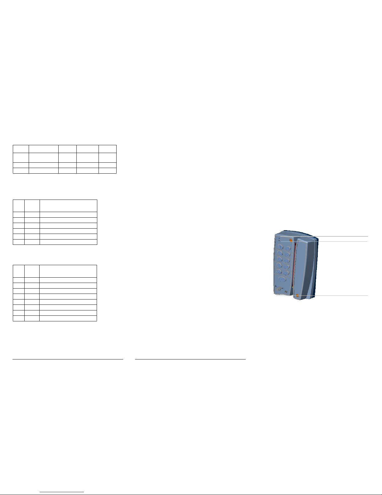
Control LED
Power LED
Communication cable
 Loading...