

Page 1
PRX-40 B
Product Manual
Page 2

PRX-40B
Manual 5/15/08. Catalog no. 652740 Document no. 040B-222-01
All rights reserved. Reproduction or use, without express permission of editorial or pictorial content, in
any manner is prohibited. No patent liability is assumed with respect to the use of the information
contained herein. While every precaution has been taken in the preparation of this manual, Synel Industries
Ltd. assumes no responsibility for errors or omissions. Neither is any liability assumed for damages
resulting from the use of the information contained herein.
DCM and SY are trademarks of Synel Industries Ltd.
All trade names referenced herein are either trademarks or registered trademarks of their respective
companies
2
Page 3

Table of contents
1.Introduction................................................................................................ 4
2.Specifications.............................................................................................. 5
2.1Technical features..................................................................................................... 5
2.2Physical specifications.............................................................................................. 5
2.3General characteristics.............................................................................................. 5
3.Unit Layout................................................................................................. 6
4.Installation.................................................................................................. 7
4.1General...................................................................................................................... 7
4.2Finding the best location for the unit........................................................................ 7
4.3Mounting the unit...................................................................................................... 8
4.4Connecting to a Master controller............................................................................. 10
4.5Jumpers ..................................................................................................................... 11
4.6Dismounting the terminal ......................................................................................... 11
5.Operation.................................................................................................... 12
5.1Set-up mode .............................................................................................................. 12
5.2Access cards configuration (Set-up codes)............................................................... 12
6.Access cards configuration........................................................................ 15
6.1Management of Access Cards (authorized personnel).............................................. 15
6.2Communication......................................................................................................... 17
3
Page 4

PRX-40B
1. Introduction
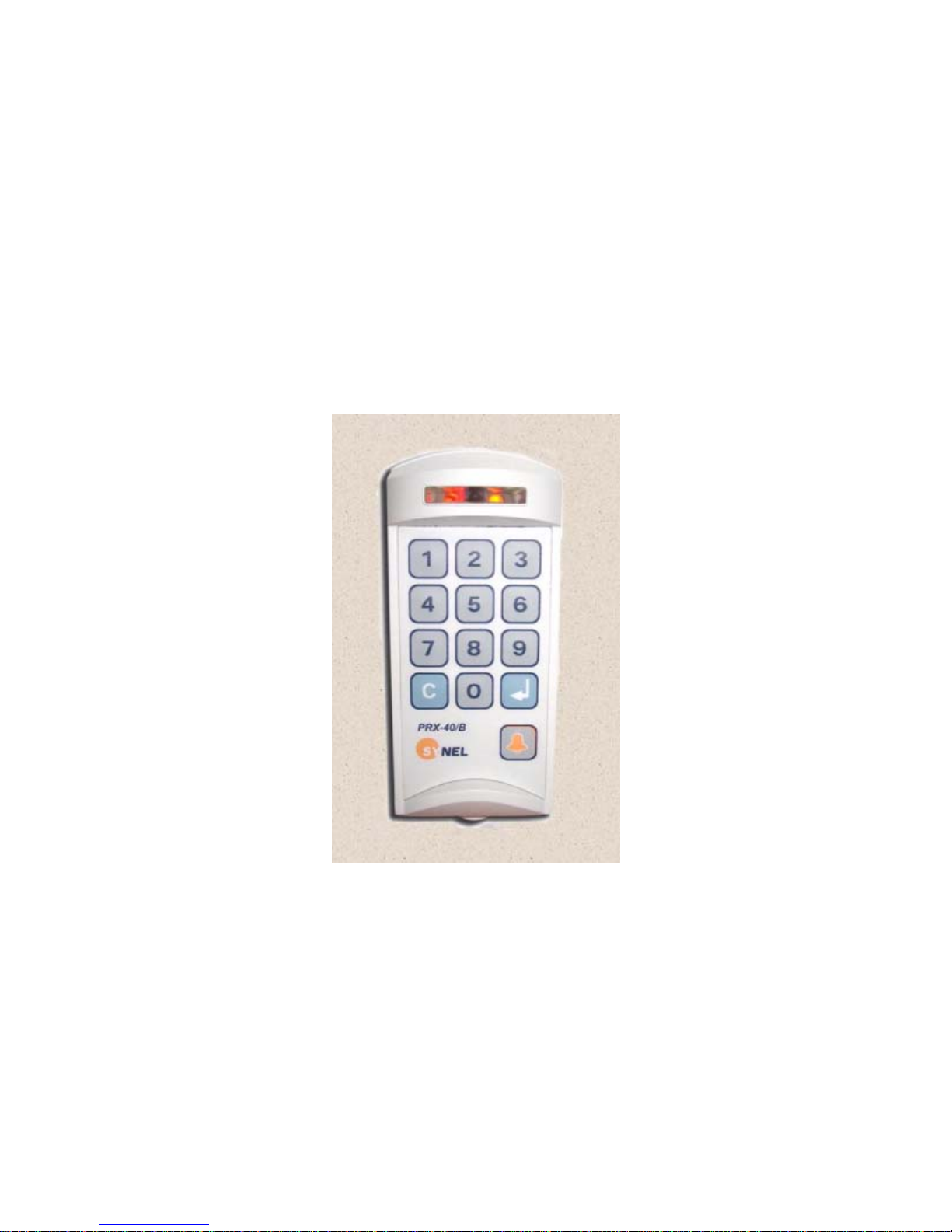
This manual deals with the PRX-40/B Proximity Access controller, one of Synel's series of compact
contactless proximity units.
PRX-40/B is a stand-alone unit developed as a compact easy-to-use proximity terminal, to be installed at
strategic locations in order to grant access to secure zones.
The PRX-40/B operates in various unit settings, according to the specific security level required to access
a specific area.
This aesthetically designed device is made of strong ABS plastic, and can be installed just about anywhere,
as a stand-alone contactless terminal or together with a master controller, connected to up to 16 reader
units. The IP44 enclosure protects the unit from water splashes and makes the PRX-40/B ideal for exposed
environments that can easily damage standard unprotected terminals.
Setting the PRX-40/B for maximum security is simple and is enabled by use of an eight digit code, chosen
by the customer. Additional access controls have been incorporated to greatly improve security.
When working in online mode (as with a Master unit) PRX-40/B uploads data from the from the other
units to it’s internal memory, thus not relaying on an
uninterrupted connection to external units.
Activation of the unit is performed when a card is held a few centimeters from the unit.
PRX-40/B can grant secure access for up to 3800 card holders, stored in an authorized list within the
controller. This list is created and edited directly in the unit's compact keyboard, eliminating the need of
connecting to a computer.
In addition, PRX-40/B can maintain a list of authorized and unauthorized employees
4
Page 5

2. Specifications
2.1 Technical features
• Typical Reading Range: 6 cm.
• Operating Frequency: 125 kHz
• RS-232 or RS-485 (ASCII); 9600 b/s Stand alone / 19000 with Master unit
• Man-machine Interface:
• Indicators for power,
• Indicators for card exception/rejection
• Indicators for keyboard entry
• 12 digit keyboard
• Bell button
• Buzzer for audio confirmation of operations
• Tamper switch enabled/disabled
PRX-40B
• Over voltage and surge protection
• Reverse voltage protection
• On board RS-232 programming of 64 kB flash memory
2.2 Physical specifications
Dimensions: 15.5 x 7 x 6.1 cm
Weight: 350g
Operating temperature: -22 to +50_C
Relative humidity: 95%
2.3 General characteristics
Output relay rating: 24 Vdc @ 3A
Alarm sensor output TTL level max @ 16 mA. , Alarm set at “High”
Sensor Input: 9 -18V @ 10mA (in Non dry contact mode)
Power supply: 12 to 15 Vdc
Door open request button - opens the door.
Door sensor - the sensor indicates that the door was forcefully opened.
Supports card holders: 3800 cards of 6 character card code length
2100 cards of 14 character card code length
5
Page 6
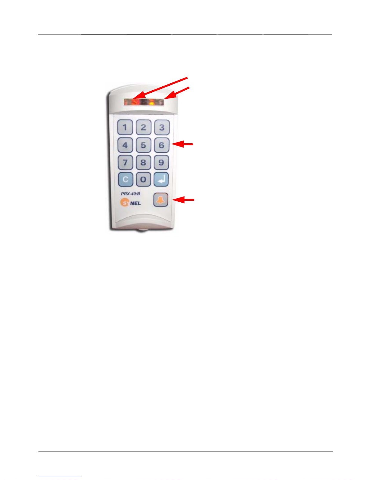
3. Unit Layout
PRX-40B
Power LED - Red
Status LED - Green - OK
Red - Wait
Keyboard
Bell button
The proximity units enclosure is a sealed IP44 enclosure and contains a small loop antenna, a transmitter
and a detector, both connected to a loop antenna.
In addition to operating as an access terminal, PRX-40 B includes additional circuitry for storing cardholder data.
Operating power for the unit comes from a wall adapter, which is be factory conn ected to either the back or
bottom of the unit.
6
Page 7

PRX-40B
4. Installation
4.1 General
The PRX-40 B proximity unit is installed at sensitive locations in order to grant access to secure areas.
The back panel of the unit serves as an installation template, to mark the location of the screws.
Mounting screws and plugs are also provided.
4.2 Finding the best location for the unit
Follow the guidelines below to find the best place to mount the terminal:
• Place the terminal by an easily accessible power outlet.
• Do not place the communication cable near a source of electromagnetic radiation or radio interference
such as power lines, large machinery, etc.
• Do not place terminal where exposed to extreme hat or cold, water, steam, violent vibrations or strong
electromagnetic radiation including high voltage power lines and electrical equipment.
• The installation location selected should be as far as possible from sources of electrical reference such
as power equipment, computers, motors, pumps, etc.
• Maintain at least a one meter distance from computer displays.
• Keep the cable by at least 30 cm away from any other cable.
• Use a power adaptor dedicated to the proximity unit. Make sure the adapter carries a safety recognition
marking such as UL, CSA or CE.
• If you are installing more than one
distance of at least 50 cm from one another (5 times the unit reading limit).
• Use a linear power supplier and not a switching power supplier which generates an electro-magnetic
field that shortens the reading range.
It is advisable to connect an independent power supplier to the reader.
• Make sure there are no metallic materials surrounding the unit.
• When mounting on a drywall (gypsum wall), make sure that there are no rear metallic reinforcements to
the wall.
• Make sure that it is safe to drill into the wall at the desired location.
• The terminal should be mounted at employee eye-height. Consider accessibility of handicap users, if
necessary. The standard recommended height is 140cm (4’7”).
• Place the reader so that the user will be fully facing it when swiping the badge since this is the best
swiping position.
Synel proximity reader, make sure the readers are installed at a
Caution: The terminal contains computer components. Thus should not be mounted where it will be
exposed to extreme heat or cold, water, steam, violent vibrations, high electromagnetic
radiation including high voltage power lines and electrical equipment.
7
Page 8

PRX-40B
4.3 Mounting the unit
1. Select a location for the terminal using the following guidelines for finding the best location:
2. Hold the mounting template to the wall and mark the places to drill holes for the screws and cables.
3. Drill the holes for the connection cable and screws (with 6mm. drill bit).
4. Inset the screw anchors for either plaster or concrete, as needed.
5. Thread the cable through the wall and connect to external components as needed.
See the Connect wires section below for cable connection according wire color coding.
6. Mount the panel to the wall and adjust it so that it is straight and the cable is in place.
7. Slide the unit downward onto to the mounting panel.
The hinges at the side of the panel (1) should slide into the track of the mounting panel (2).
1
2
8. Once the unit is in place you can screw the security screw, connecting between the panel and the
unit, at the top of the unit and panel.
8
Page 9

4.3.1 Connect wires
The wires are connected to external components as listed in the table below.
Connector J5/14
PRX-40B
Wire No. Wire Function Present Color Code
1 Vin Power (VCC) Red
2 Gnd Black
3 - TxRx RS-485 Grey
4 + TxRx RS-485 Purple
5 TxD RS -232 White
6 RxD RS -232 Green
7 Tamper Control Brown
8 Normal Neutral (C) Blue
9 Normally Closed (N.C) Yellow
10 Normally Open (N.O.) Orange
11 Bell (1) Pink
12 Bell (2) Light green
13 (optional) as needed Light blue
14 (optional) as needed Brown + White or Brown + Black
9
Page 10

Wire connection diagram
PRX-40B
4.4 Connecting to a Master controller
10
Page 11

4.5 Jumpers
Jumper Function Default
JP2 (SMD) JP2 closed and JP3 open = Linear decoding
JP3 (SMD)
JP4 (SMD) Cross point decoding (currently NA)
JP7 (SMD) Connect RS-485 termination resisto r Open
JP10 (TH) W.D. Reset for the master CPU- [1-2] Closed
JP11(TH) PSEN (Programming) - must be closed when programming the master
JP12 (SMD) Tamper switch enabled [1-2] closed
JP20 (T.H) Closed- Stand alone
JP21 (T.H) Contacts switching protection in DC- closed
JP22 (SMD) Connecting clock to slave CPU [2-3] closed
JP23 (T.H) Select sensor option:
JP24 (T.H) Reset for the slave/reader CPU- [2-3] closed
JP2 open and JP3 closed = Synel decoding
Programming of the master CPU - [2-3] Closed
CPU.
Tamper switch disabled [2-3] closed
Open- Online with Master
Contacts switching protection in AC- open
[1-2] and [3-4] Closed - dry contact
[2-3] Closed - AC/DC
Programming of the slave/reader CPU [1-2] Closed
Linear
[1-2] closed
Open
[2-3] closed
Closed
(up to version 3.04
later set via Setup)
Closed
[1-2] and [3-4] closed
[2-3] closed
PRX-40B
4.6 Dismounting the terminal
1. Remove the security screw from the top of the unit.
2. Press the clasps at the bottom of the mounting panel and lift the unit upward.
11
Page 12

PRX-40B
5. Operation
5.1 Set-up mode
PRX-40/A programming can be divided to three categories:
1. Access Cards configuration (authorized personnel)
2. General definitions
3. Indicator definitions
All definitions of Management modes are listed in the table below.
The codes in the table below can be used only after completing set-up mode
Step 1: Press 3 times simultaneously on function keys 1 & 2 (each time will be followed by a short beep
and an orange led will be lit).
Input Indicator signalling
1st 1&2 Short beep+2nd red led ON
2nd 1&2 Long beep+2nd red led ON
3rd 1&2 2 long beeps+2nd green led flashes
as follows:
Step 2: Enter the 8 digit master code (the default number is 12345678). Then insert the relevant set-up
code (see next page).
5.2 Access cards configuration (Set-up codes)
Name Code Parameter Comments Default
Work mode
Control Door
Reset alarm 4 When the alarm is in latch (turned ON)
Check ID Address
Door opening time
Card reading/check
parameters
0 1 -
Stand alone
Online
8
0
7
000-255 In 1/10 seconds step (0 to 25.5
10
1,2- Start position (01-37)
11
3,4- Length (01-06)
5,6- To tal Characters
From version 3.04
Until now this was done in
jumper JP20.
Enter Master code and
press 0.
Long buzzer - tens
Short buzzer - unique
sec.)
3 sec.
01
16
00
12
Page 13

PRX-40B
Operation mode 12 0 -
New master code
Communication ID 14 1-32 Defines terminal ID 01
New global code
Insert card using card 20 In Operation Mode 4
Delete card from list using
card
Insert card using keyboard 22 In Operation mode-12 press key no.
Delete card using keyboard
Insert card by Index 24 Card index 4 digits
13
15
21 Card
23 Enter Card number
Card only
Global code only
1 -
Card or code (card no.)
2 -
Card and global code
3 -
Card and pin code
4 -
Card and finger
5-
Code and finger (finger only)
6-
Card and card
700000000-99999999 8 digit code
4 digit new code 9999
1. Swipe card
2. Insert pin code
3. Terminal reverts to 1.
---------------------------Fingerprint- Operation Mode 5
1. Swipe card (2 beeps confirm
swipe).
2. Place finger
3. Terminal reverts to 1.
----------------------Modes 5-6 only with PrintX
-----------------------
Revert to Normal mode by
pressing Enter in terminals
that have this key or press 7&8
simultaneously.
----------------------Mode 5 only with PRintX*
There is a
different
code for
each
employee
To revert to normal mode press
4 to enter mode 4.
1. Key-in card number
2. Enter pin code
Terminal reverts to 1.
----------------------------Fingerprint - In Operation Mode-12
press key no. 6 to enter Mode 6
1. Key-in code (depends on card
length).
2. Place finger
Terminal reverts to 1.
from 0000-0300
7&8 simultaneously or press
the Enter in terminals that
have one
--------------------------------
Mode 6 only with PRintX
Highest possible index depends
on card length (code 11)
Delete card by Index 25 Card inde x 4 digits
Sensor input operation
mode
Sensor type
Door sensor active time
(open door)
30
31
32
0 -
Door open request button
1 -
Door Sensor
0 -
N.O
1 -
N.C
000-255 Define number of seconds
when door is open
0 - Door
open request
button
1 - N.C
15 sec.
13
Page 14

PRX-40B
Toggle relay mode
Toggle relay timeout
Set reject list flag 35 1- set
Set/Reset auto finger
detect
External magnetic reader
or open door button
Door monitor button 38 0 -
Duress code enable/disable
Alarm mode
Alarm pulse activating
time
Define duress code 53 0000-9999 Active in operation mode 123
Open door button 57 1 -
Erase all cards 60 Enter Access code 6
Initialisation of memory 61 Enter Access code 6
Delete all fingerprints
from fingerprint reader
0 - Disable
33
1 - Enable
00-99 In seconds 00- Disabled
34
0- reset
36 1 -
37 0 -
50 01Disable
51
52 0000-9999 Key-in time in a four digit for-
62 Enter Master code Version 2.08 with type S.
set
0 -
reset
Magnetic reader
1 -
Open door push button
no buzzer
1 -
buzzer
Enable
0 -
Latch (LED is on)
1 -
Pulse (LED is off)
send request to master
0 -
open door
Enter Setup code (master code)
Enter Setup code (master code)
In minutes 0- Disable
with card only mode 0
Version 2.08 with type S.
Version 3.04
If door is open too long sound
buzzer.
Version 3.04
Activating alarm and relay out-
put
1 = LED is off depending on
pulse time (code 52)
mat: 10 sec. = 0010
& 124
0 sec.
Note: After swiping all cards, you should wait time-out or press 7&8 simultaneously (press Enter in ter-
minals that consist of such a key) once. Then all data will be saved!
14
Page 15

PRX-40B
6. Access cards configuration
Time Out
After every entry a LED is lit (while waiting for the next entry). After the LED goes out the unit exits the
“Programming Mode” and resets (action must be repeated from the beginning).
6.1 Management of Access Cards (authorized personnel)
Managing access Cards can be performed three ways:
Using Keyboard - Keying-in the keyboard the card number
Using Card - Swiping the card
By Index - Enables deleting an employee without a card
Using the Keyboard
Build list:
After entering set-up mode key-in code 22 (key-in card number to list) (Up to 13 characters in Linear
decoding) and key-in all relevant cards. After each keyed-in card number 2 short beeps will indicate that
the number was registered successfully. After keying-in all card numbers press 7&8 simultaneously (mandatory) (press Enter in terminals that consist of an Enter key) in order to revert to normal mode.
Note: In operation mode 4 - card and pin code, the user must key-in the card number and then key-in the
pin code for each card (4 digit code).
Delete list:
After entering set-up mode key-in code 23 (Delete card by keyboard) and key-in all irrelevant cards. After
each keyed-in card number 2 short beeps will indicate that the number was deleted successfully. After keying-in all card numbers press 7&8 simultaneously (mandatory) (press Enter in terminals that consist of an
Enter key) in order to revert to normal mode.
Using Card
Build list:
After entering set-up mode key-in code 20 (Insert card to list by card) and swipe all relevant cards. After
each swiped card 2 short beeps will indicate that the number was registered successfully. After swiping all
cards press 7&8 simultaneously (mandatory) (press Enter in terminals that consist of an Enter key) in
order to revert to normal mode.
Note: In set-up code 12: operation mode no. 4 - car d and pin code, the user must swipe the card and then
key-in the code (a 4 digit code).
Delete list:
After entering set-up mode key-in code 21 (delete card by card) and swipe all irrelevant cards. After each
swiped card 2 short beeps will indicate that the number was deleted successfully. After swiping all cards
press 7&8 simultaneously (mandatory) (press Enter in terminals that consist of an Enter key) in order to
revert to normal mode.
Note: Whenever a task is completed successfully, a LED flashes and the buzzer beeps.
By index
Insert cards:
After entering set-up mode, key-in code 24 (Insert card by Index) and key-in a 4 digit index, swipe card. 2
short beeps will indicate that the number was registered successfully. After swiping all cards press 7&8
simultaneously (mandatory) (press Enter in terminals that consist of an Enter key) in order to revert to
15
Page 16

PRX-40B
normal mode.
Delete cards:
After entering set-up mode key-in code 25 (delete card by index) and key-in a 4 digit index. 2 short beeps
will indicate that the index was deleted successfully. After swiping all cards press 7&8 simultaneously
(mandatory) (press Enter in terminals that consist of an Enter key) in order to revert to normal mode.
Terminology
Card Only - Control is performed by Card only.
Global Code only - common global code (4 digit code – used by all card-holders).
Card or code - Control is performed by Card or keying-in number of card (the length of the keyed-in num-
ber must be identical to the defined card length).
Card and Global Code - Control is performed by Card and a common global code (four digit code – used
by all card-holders).
Card and PIN Code – Control is performed by Card and a personal four digit code. This mode is the most
secure.(4 digit code – used by each card-holder).
6.1.1 General definitions
Open Door
Access can be given by using a Master Code. After entering “Programming Mode,” enter “0”.
Open Door Time
It is possible to adjust the “window” of accessibility during which a door opens when accessed. To change
the accessibility time, after entering the “Programming Mode,” enter “10” and then four digits. For example if you enter 0015, the accessibility time is 1.5 seconds.
Set Global Code
You can change a Global Code by way of “Instruction Code” – 15. After entering “Programming Mode”
enter “15” and afterward a four digit number that will be the new Global Code.
Set New Master Code
The Master Code can be change by way of “Instruction Code” – 13. After entering “Programming Mode”
enter “13” followed by a eight digit number that will serve as a new master Code.
Note: It is recommended to change master code when setting up.
Erase All
Warning:
! Cards can not be restored after erased!
After entering the “Programming Mode,” enter “6” and then eight digits Master code.
6.1.2 Indicators definitions
After entering setup mode:
Input Operation Mode
Code 30 --> 0 = Door open request button
As a result the door will open and the output = bypass
1 = Door sensor
As a result the output = alarm will be activated (led/buzzer)
Sensor type
Code 31--> 0 = The sensor will function as Normally Open.
16
Page 17

1 = The sensor will function as Normally Closed.
Alarm mode
Code 51--> 0 = Latch. The alarm does not go off unless it is turned off
manually.
1 = Pulse. The alarm goes off after the defined time-out.
Alarm pulse activating time
Note: Relevant when alarm is in pulse mode.
Code 52--> 0000-9999 seconds (always key-in time in 4 digits format)
Sensor door activating time
Code 32--> 000-255 time-out seconds. The alarm will be activated after
the defined time-out.
Duress code enable/disable
Code 50--> 0 = Disable
1 = Enable
In operation modes card and global code or card and pin code
enables activating the alarm and the door simultaneously.
PRX-40B
Define Duress code
Code 53--> 0000-9999
Enables defining what will be the duress code
Card parameters
Refer to how the proximity track will be read:
2 digits Start position (01-37) Card number offset
2 digits Length (01-06) Card number length
2 digits Total characters Number of digits on card (when defining 00 - doesn’t check
card length- accepts all card lengths up to 6)
Reset alarm
In set-up mode, after keying-in code 51, key-in 4 to shut-off the alarm.
6.2 Communication
Interfacing the host is performed via the Master unit. Communication between the master unit and the terminals is performed at 19200 bps.
Downloading card numbers from Master to terminals
As of Master version 3.20 there is an additional option “Send offline list to Access units”. All card numbers that are marked as (see Falcon | Personnel | Card Type | Active - Allowed offline) Active - Allowed
offline will be sent from the Master to the terminals. When communication is stopped the Terminal will
enable access for the cards as mentioned above.
17
Page 18

PRX-40B
6.2.1 Communication cables characteristics
Follow the listed guidelines when installing the communications cables:
The cable should not be installed near EMI factors, such as:
• Motors, generators, alternators, and transformers
• Air conditioners, elevators
• Radio/television transmitters, signal generators and internal communication networks
• Cables: within 30 cm. (1 foot) of power lines of less than 5 KVA.
• Cables should not be within 60 cm. (2 feet) of power lines in the 5-10 KVA range.
Cables should not be within 1.5 meters (5 feet) of power lines of more than 10 KVA. The cables should not
run parallel to power lines for more than 15 meters (49 feet).
It is best to use a single cable for the communication line. If it is not possible to use a continues cable only
one indoors connection is allowed, constructed in one of these options:
1. Using two connectors with appropriate shielding and cover.
2. Using a connection box.
For aerial installation, use N.Y.Y. shielded cables.
18
 Loading...