

Page 1
-
1
Manual 7/12/09. Catalog no. 650460 Document no. FPR-PRX-222-01
PRX-40/B
Terminal
&
PrintX FPR
(FingerPrint
Reader)
STAND-ALONE TERMINALS
Product Manual
Page 2

-
2
All rights reserved. Reproduction or use, without express permission of editorial or pictorial content,
in any manner is prohibited. No patent liability is assumed with respect to the use of the information
contained herein. While every precaution has been taken in the preparation of this manual, Synel
Industries Ltd. assumes no responsibility for errors or omissions. Neither is any liability assumed for
damages resulting from the use of the information contained herein.
DCM and SY are trademarks of Synel Industries Ltd.
All trade names referenced herein are either trademarks or registered trademarks of their respective
companies
Page 3

3
Contents
Introduction .................................................... 5
Apparatus........................................................ 7
Technical Specifications................................ 8
3.1Electrical characteristics 8
3.2Package 9
Installation..................................................... 10
Finding the best location for the units ....... 10
Mounting PRX-40/B and PrintX FPR........... 12
Connecting the Cables ................................ 15
7.1PRX-40/B Connection Wires 17
Jumpers ........................................................ 20
8.1PRX-40/B 20
Setting-up the Standalone unit ................... 21
9.1To use Proximity Card and Fingerprint mode: 21
9.2Setting Proximity Card parameters: 21
9.3Entering Proximity Cards and Fingerprints to the unit:
22
9.4To use Pin number and Fingerprint mode: 22
9.5Entering Pin numbers and Fingerprints to the unit:
22
9.6Specify if using Identify or Verify mode: 23
Operation ...................................................... 24
10.1PrintX-FPR Operation 24
Page 4

4
Communication ............................................ 26
Communication cables characteristics ..... 26
Fingerprint Best use Guidelines................. 27
Troubleshooting ........................................... 28
Appendices:
Detailed instructions for Standalone Set-up 30
1.1Access cards configuration (Set-up codes) 30
1.2Access cards configuration 34
Additional Stand alone unit combination options
39
Page 5

Back to Table of Contents
5
1Introduction
The PRX-40/B reader and PrintX-FPR fingerprint reader Standalone, as a stand alone biometric
solution for access control.
The proximity and biometric units are adjacently installed at sensitive
locations for granting access to secure zones.
Setup, management of authorized, and definitions are all done directly on the
units. Defining parameters in PRX-40/B and PRintX-FPR is simple, and the
templates and an authorized list are created and edited using the keyboard.
P
RX-40/B & PrintX-FPR were developed as compact, easy-to-use terminals,
granting access to secure areas. They work with various unit settings,
according to a predefined security level. These devices are made of strong
ABS plastic.
Defining parameters is simple while maximum security is enabled by using
the set-up 8 digit code (the default number is 12345678) maximizing security.
In stand alone mode these units grant secure access for approximately 285
card holders, stored in an authorized list within the terminal. This list is created and edited on the
unit’s compact keyboard, eliminating the need of connecting to a computer.
These terminals can manage unauthorized (black list) or authorized (white list) employee lists for
access control purposes.
The PRX-40/B and PRintX-FPR Standalone can be used in the following modes:
Identification - In this mode user is only identified by a fingerprint and is not verified by an
additional means of identification.
The finger is placed on the sensor and is either accepted or rejected immediately.
In this mode, the keyboard unit can be installed in a different location such as on the other side of the
door. In this case The user is identified my finger on one side and by card or pin number on the other
side of the door.
Identification mode supports up to 9,000 authorized people.
Page 6

Back to Table of Contents
6
Verification - In this mode user is identified by wither a card or by pin number on the key board, and
then verifies their identity with by fingerprint.
Verification can be done in the following ways:
• Swipe card > Fingerprint
• Pin number > Fingerprint
Access is available for up to 9,000 card holders.
Page 7
Back to Table of Contents
7
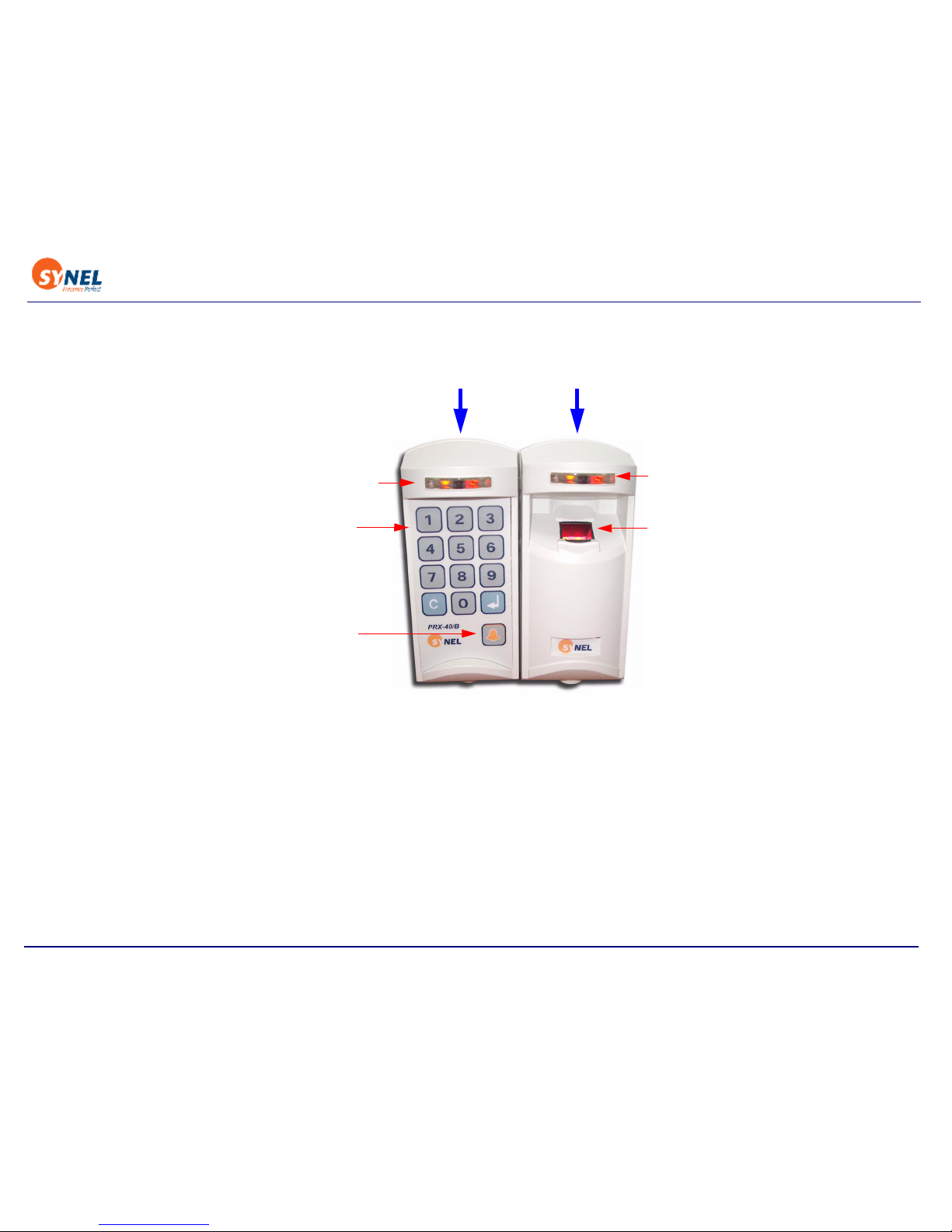
2 Apparatus
In stand-alone mode (when the device functions as a controller) this unit has additional circuitry for
storing card-holder data.
PRX-40/B
Pr
i
ntX FPR
LED Operation
Status Indicator
LED Operation
Status Indicator
Fingerprint sensor
Keyboard
Bell button
Page 8

Back to Table of Contents
8
3 Technical Specifications
PRX 40/B
• Dimensions: 15.5 x 7 x 6.1 cm
• Weight: 350 gr
• Operating temperature: -10 to +50°C
PrintX FPR
• Dimensions: 15.5 x 7 x 6.1 cm
• Weight: 350 gr
• Operating temperature: -10 to +50°C
3.1 Electrical characteristics
• Output relay rating: 24 V @ 3 A
• Tamper sensor output TTL level max @ 16 mA
Page 9
Back to Table of Contents
9
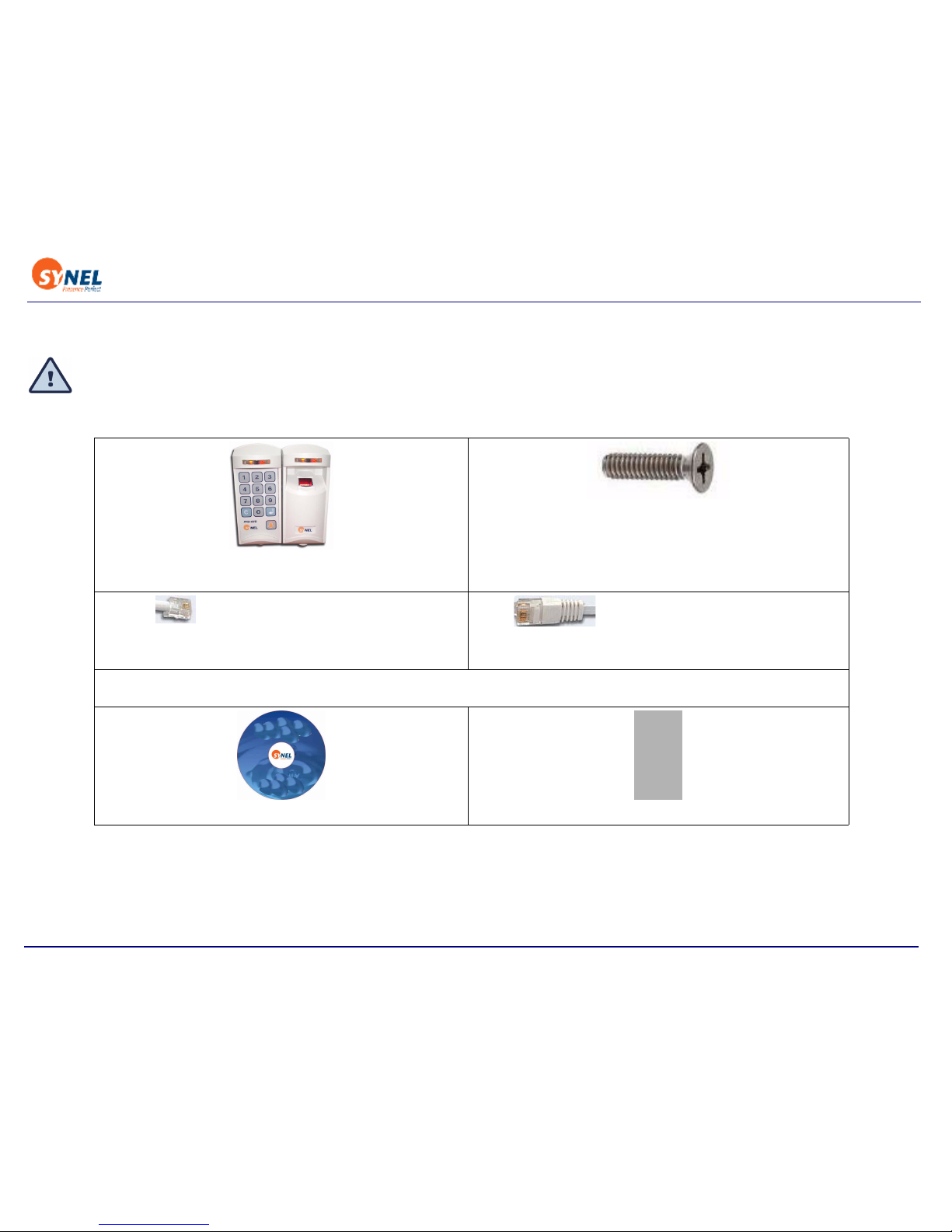
3.2 Package
The terminal package contains:
Check the box and contents for signs of damage that may have occurred during shipment. Don’t throw away
the box or any of the packing materials
1x PRintX FPR unit
1x PRX 40/B unit
A mounting set that includes:
2 screws for mounting the mounting panel
2 screw for securing the unit to mounting panel
Wall anchors:4 Brick + 4 Plaster
1x RJ-11 Connection box with cables for 12V
power connection (for PRX 40/B)
1x RJ-45 Connection box with 5V power input
(PrintX FPR)
PRintX/P power supply adaptor:
5 Volt/1 A stabilized wide range input 100-240 AC input
User guide on CD
2x Mounting pannels
Page 10

Back to Table of Contents
10
4 Installation
5 Finding the best location for the units
Follow the guidelines below to find the best place to mount the terminal:
• Place the units by an easily accessible power outlet.
• Do not place communication cables near a source of electromagnetic radiation or radio interference
such as power lines, large machinery, etc.
• Do not place the units where exposed to extreme hat or cold, water, steam, violent vibrations or
strong electromagnetic radiation including high voltage power lines and electrical equipment.
• The installation location selected should be as far as possible from sources of electrical reference
such as power equipment, computers, motors, pumps, etc.
• Maintain at least a one meter distance from computer displays.
• Keep the cable by at least 30 cm away from any other cable.
• Use a power adaptor dedicated to the proximity unit. Make sure the adapter carries a safety
recognition marking such as UL, CSA or CE.
• If you are installing more than one
Synel proximity reader, make sure the readers are installed at a
distance of at least 50 cm from one another (5 times the unit reading limit).
• Use a linear power supplier and not a switching power supplier which generates an electromagnetic field that shortens the reading range.
It is advisable to connect an independent power supplier to the reader.
• Make sure there are no metallic materials surrounding the unit.
• When mounting on a drywall (gypsum wall), make sure that there are no rear metallic
reinforcements to the wall.
• Make sure that it is safe to drill into the wall at the desired location.
Page 11

Back to Table of Contents
11
• The units should be mounted at employee eye-height. Consider accessibility of handicap users, if
necessary. The standard recommended height is 140cm (4’7”).
• Place the reader so that the user will be fully facing it when swiping the badge since this is the best
swiping position.
Caution:The terminal contains computer components. Thus it should not be mounted where it
will be exposed to extreme heat or cold, water, steam, violent vibrations, high electromagnetic
radiation including high voltage power lines and electrical equipment.
Page 12

Back to Table of Contents
12
6 Mounting PRX-40/B and PrintX FPR
1. Select a location for the terminal using the following guidelines for find-
ing the best location, above.
2. Hold the mounting template to the wall and mark the places to drill holes
for the screws and cables.
3. Drill the holes for the connection cable and screws (with 6mm. drill bit).
4. Inset the screw anchors for either plaster or concrete, as needed.
5. Thread the cable through the wall and connect to external components
as needed.
Mount the panel to the wall and adjust it so that it is straight and the
cable is in place.
Page 13

Back to Table of Contents
13
6. Slide the unit downward onto to the mounting panel.
The hinges at the side of the panel (1) should slide into the track of the mounting panel (2).
1
2
Page 14

Back to Table of Contents
14
7. Once the unit is in place you can screw the security screw, connecting between the panel and the
unit, at the top of the unit and panel.
Page 15

Back to Table of Contents
15
7 Connecting the Cables
PRX-40B Communication Box
Page 16

Back to Table of Contents
16
Print-X-FPR Communication Box
Page 17

Back to Table of Contents
17
Wire connections of Fingerprint connection box
Wire connections of Proximity Card connection box
7.1 PRX-40/B Connection Wires
The wires are connected to external components as listed in the table below.
From Name Color RJ11 Box1
P2/5 +5Vdc Purple 7
P3/5 +5Vdc Brown 7
P2/1 GND Blue/White 3
P2/9 GND Brown/White 3
P2/3 Host Rx Orange 2
P2/2 Host Tx Green 4
From Name Color RJ45 Box2
P1/1 Clock /D1 Green 6
P1/2 Clock /D0 Blue 7
P1/4 +5Vdc Red 3
P1/5 GND Black 4
LED1/2 (+) C.Anode Black 3
LED1/2 (G) Green LED Light Green 5
LED1/2 (R) Red LED Pink 2
Wire No. Wire Function Present Color Code
1 Vin P ower (VCC) Red
2 Gnd Black
3 - TxRx RS-485 Grey
4 + TxRx RS-485 Purple
5 TxD RS -232 White
6 RxD RS -232 Green
7 Tamper Control Brown
8 Normal Neutral (C) Blue
9 Normally Closed (N.C) Yel l ow
10 Normally Open (N.O.) Orange
Page 18

Back to Table of Contents
18
Wire connection diagram
11 Bell (1) Pink
12 Bell (2) Light green
13 (optional) as needed Light blue
14 (optional) as needed Brown + White or Brown + Black
Page 19

Back to Table of Contents
19
PRX-40/B Wire connection diagram
Page 20

Back to Table of Contents
20
8Jumpers
8.1 PRX-40/B
Jumper Function Default
JP2 (SMD) JP2 closed and JP3 open = 13 digits decoding
JP2 open and JP3 closed = 14 digits decoding
13 digits
JP3 (SMD)
JP4 (SMD) Cross point decoding (currently NA)
JP7 (SMD) Connect RS-485 termination resistor Open
JP10 (TH) W.D. Reset for the master CPU- [1-2] Closed
Programming of the master CPU - [2-3] Closed
[1-2] closed
JP11(TH) PSEN (Programming) - must be closed when programming
the master CPU.
Open
JP12 (SMD) Tamper switch enabled [1-2] closed
Tamper switch disabled [2-3] closed
[2-3] closed
JP20 (T.H) Closed- Stand alone
Open- Online with Master
Closed
JP21 (T.H) Contacts switching protection in DC- closed
Contacts switching protection in AC- open
Closed
JP22 (SMD) Connecting clock to slave CPU [2-3] closed
JP23 (T.H) Select sensor option:
[1-2] and [3-4] Closed - dry contact
[2-3] Closed - AC/DC
[1-2] and [3-
4] closed
JP24 (T.H) Reset for the slave/reader CPU- [2-3] closed
Programming of the slave/reader CPU [1-2] Closed
[2-3] closed
Page 21

Back to Table of Contents
21
9 Setting-up the Standalone unit
Once the units are hooked up you can set them.
Following are the steps for basic setup. For additional commands refer to the command list in
“Detailed instructions for Standalone Set-up” on page 30.
The general workflow of setting the unit is as follows:
Step 1.Press 3 times simultaneously on function keys 1 & 2 (each time will be followed by a short
beep and an orange led will be lit).
Step 2.Enter the 8 digit master code (the default number is 12345678). Then insert the relevant set-
up code (see next page).
Follow the task below for specific instruction of the tasks.
9.1 To use Proximity Card and Fingerprint mode:
Step 1.Press 1 key and 2 key 3 times simultaneously.
Step 2.Key in Master code (8 digits).
Step 3.Key in code 12.
Step 4.Key in code 5.
Step 5.Press Enter to save and exit.
9.2 Setting Proximity Card parameters:
Step 1.Press 1 key and 2 key 3 times simultaneously.
Step 2.Key in Master code (8 digits).
Step 3.Key in code 11.
Step 4.Enter a string that is made up 6 digits where:
places 1,2 = the position in the string where the relevant code used
Input Indicator signalling
1st 1&2 Short beep+2nd red led ON
2nd 1&2 Long beep+2nd red led ON
3rd 1&2 2 long beeps+2nd green led flashes
Page 22

Back to Table of Contents
22
places 3,4 = the length of the relevant code used
places 5,6 = the total characters that can be used for the card code. This is used of you need to
restrict use of a certain type of card with a known number of digits in the code. If not relevant use
00.
For example if the card code is 000012345111, and you are only reading 12345, the string will
be 050500 because you are starting to read at position 5 and you are reading only the next 5 digits.
Step 5.Press Enter to save and exit.
9.3 Entering Proximity Cards and Fingerprints to the unit:
Step 1.Press 1 key and 2 key 3 times simultaneously.
Step 2.Key in Master code (8 digits).
Step 3.Key in code 20.
Step 4.Bring card to be read by unit.
Step 5.When the light flashes enroll fingerprint to match card.
Step 6.Press Enter to save and exit.
Step 7.Continue for all users.
9.4 To use Pin number and Fingerprint mode:
Step 1.Press 1 key and 2 key 3 times simultaneously.
Step 2.Key in Master code (8 digits).
Step 3.Key in code 12.
Step 4.Key in code 6.
Step 5.Press Enter to save and exit.
9.5 Entering Pin numbers and Fingerprints to the unit:
Step 1.Press 1 key and 2 key 3 times simultaneously.
Step 2.Key in Master code (8 digits).
Step 3.Key in code 22.
Step 4.Enter pincode to unit.
Page 23

Back to Table of Contents
23
Step 5.When the light flashes enroll fingerprint to match card.
Step 6.Press Enter to save and exit.
Step 7.Continue for all users.
9.6 Specify if using Identify or Verify mode:
In identify mode the user places a finger and if the fingerprint is in the system the user is allowed to
enter. In verify mode the user is let in only of both card or pin code and fingerprint match what is in
the system.
Step 1.Press 1 key and 2 key 3 times simultaneously.
Step 2.Key in Master code (8 digits).
Step 3.Key in code 36.
Step 4.Key in:
0 for verify
1 for identify
Step 5.Press Enter to save and exit.
Page 24

Back to Table of Contents
24
10 Operation
10.1 PrintX-FPR Operation
• Enrol - New fingerprint templates can be enrolled at the unit and stored for future recognition.
• Verification - The verification mode of access control requires a card/code combination. The
template is stored with reference to a card/code. Up to 3800 card/code
combinations and templates are stored. When an employee swipes a card
or keys-in a code, the unit checks whether the card/code number exists,
if it does the unit also checks the template assigned to that number.
• Identification - The identification mode does not require a card/code
combination. Up to 9090 fingerprint templates are stored in the terminal’s
memory. When an employee places a finger on the sensor, the FP (fingerprint) unit polls all existing
templates for a match and confirms or rejects access accordingly.
Erase - deleting one or all stored templates from the memory. This option os only available via
software used to manage this unit. Otherwise all of the templates remain stored in the FPU memory.
Supports card holders:
• 3800 cards of 6 character card code length
• 2100 cards of 14 character card code length
Template quota is as follows:
• Verification - 3800-2400
• Identification - 9000 using PrintX FPR memory only
Page 25

Back to Table of Contents
25
10.1.1PrintX-FPR Operation Status Indicator LED
Card Reader LED
(Left side)
Fingerprint LED
(Left side)
Green Allowed card Successful operation.
Red Flashing x3 -Wrong
card
Unidentified/ Wrong
fingerprint
Orange Non-flashing
Waiting for finger
Flashing x1 per second
Waiting for fingerprint
verification.
Flashing x2 per second
Waiting for fingerprint
identification.
Page 26

Back to Table of Contents
26
11 Communication
Interfacing the host is performed via the Master unit. Communication between the Master unit and
the terminals is performed at 19200 bps.
Downloading card numbers from Master to terminals
Downloading card numbers from Master to terminals is done using the “Send offline list to Access
units” option. All card numbers that are marked as Active - will be sent from the Master to the terminals (see Falcon Manual). When communication stops the Terminal will enable access for the cards as
mentioned above.
12 Communication cables characteristics
Follow the listed guidelines when installing the communications cables:
• The cable should not be installed near EMI factors, such as:Motors, generators, alternators, and
transformers, Air conditioners, elevators, Radio/television transmitters, signal generators and
internal communication networks
• Cables: within 30 cm. (1 foot) of power lines of less than 5 KVA.
• Cables should not be within 60 cm. (2 feet) of power lines in the 5-10 KVA range.
Cables should not be within 1.5 meters (5 feet) of power lines of more than 10 KVA. The cables
should not run parallel to power lines for more than 15 meters (49 feet).
It is best to use a single cable for the communication line. If it is not possible to use a continues cable
only one indoors connection is allowed, constructed in one of these options:
1. Using two connectors with appropriate shielding and cover.
2. Using a connection box.
For aerial installation, use N.Y.Y. shielded cables.
Page 27

Back to Table of Contents
27
13 Fingerprint Best use Guidelines
• You should always touch the conductive plastic before touching the PRintX/P sensor in order to
safely discharge any static electricity on your skin or clothing.
• Place the fingerprint sensor close to a heating source, such as a radiator or hot plate
• Spill any liquids on the sensor with the exception of isopropyl alcohol.
• Subject the fingerprint sensor to heavy shocks or vibrations.
• Allow the sensor to come in contact with metallic objects.
Page 28

Back to Table of Contents
28
14 Troubleshooting
[Question]
If I already have a PRX-40 B and a PrintX-FPR unit can I set them up together as a standalone unit?
[Answer]
Yes, you do not have to use the kit, you can set these units up as standalone if the following
conditions are met:
• You need to have a reader of type FPU-S
• The firmware version of the reader needs to be version 2.08 or higher.
• You can have either an Optic or TC (Capacity) FPU.
If these conditions are met, contact technical support to install Unifinger and change the baudrate.
[Question]
The controller is not enrolling the fingerprints. Is there something I should check?
[Answer]
In PrintX-FPR Programming mode, check that code 36 is chosen as Auto-identify mode.
[Question]
How can I tell if the FPU I have is Optic or TC (Capacity)?
[Answer]
You can see the difference easily according to the following characteristics:
A capacity (TC) reader has hozinontal lines on it’s surface.
An optic reader has a light inside of it.
Page 29

Back to Table of Contents
29
14.0.1Access Control using PrintX-FPR
3. Place the user-finger on the fingerprint sensor.
4. A fingerprint recognized as matching a fingerprint template stored in the unit allows access -
activates door relay.
An un-recognized fingerprint denies access and initiates a buzzer sound - door relay is not
activated.
14.0.2FPU operation - Instructions and Best practices
1. Do not use your thumb to enrol.
2. Place the higher joint of your finger on the ridge lock and lower your finger onto the sensor
surface (make sure all other fingers are held straight to avoid creating an angle between the
enrolled finger and the sensor surface - incorrect positioning).
3. Touch the sensor's plastic casing (black) in order to discharge static electricity. Keep your finger
steady!
4. Press your finger gently onto the panel, avoid excessive pressure as it will blur the print.
5. Make sure your finger is touching the sensor’s drive ring.
6. Use the same finger for enrolment
as well as for verification.
7. If your finger is extremely dry, touch your forehead or the side of your nose before placing it on
the sensor.
Page 30

Back to Table of Contents
30
Appendix 1 -Detailed instructions for Standalone Set-up
The following section includes all of the configuration codes that can be used to set-up the standalone
unit. For detailed instructions about the basic settings for the unit, refer to “Setting-up the
Standalone unit” on page 21.
1.1 Access cards configuration (Set-up codes)
Name Code Parameter Comments Default
Work mode 80 -
1 -
Stand alone
Online
From version 3.04
Until now this was
done in jumper
JP20.
Control Door 0 Enter Master code
and
press 0.
Reset alarm 4 When the alarm is in latch
(turned ON)
Check ID
Address
7 Long buzzer - tens
Short buzzer unique
Door opening
time
10 000-255 In 1/10 seconds
step (0 to 25.5 sec.)
3 sec.
Card
reading/
check
parameters
11 1,2- Start position (01-37)
3,4- Length (01-06)
5,6- Total Characters
01
16
00
Page 31

Back to Table of Contents
31
Operation
mode
12 0 -
1 2 3 4 56-
7-
Card only
Global code only
Card or code (card no.)
Card and global code
Card and pin code
Card and finger
Code and finger (finger
only)
Card and card
----------------------
Modes 5-6 only with
PrintX
----------------------
-
There is
a
different
code for
each
employe
e
New master
code
13 00000000-99999999 8 digit code
Communicati
on ID
14 1-32 Defines terminal ID 01
New global
code
15 4 digit new code 9999
Insert card
using card
20 In Operation Mode 4
1. Swipe card
2. Insert pin code
3. Terminal reverts to 1.
---------------------------Fingerprint- Operation Mode 5
1. Swipe card (2 beeps confirm
swipe).
2. Place finger
3. Terminal reverts to 1.
Revert to Normal
mode by pressing
Enter in terminals
tha t hav e thi s key o r
press 7&8
simultaneously.
----------------------
Mode 5 only with
PRintX*
Delete card
from list
using card
21 Card
Page 32

Back to Table of Contents
32
Insert card
using
keyboard
22 In Operation mode-12 press key
no. 4 to enter mode 4.
1. Key-in card number
2. Enter pin code
Terminal reverts to 1.
----------------------------Fingerprint - In Operation Mode-12
press key no. 6 to enter Mode 6
1. Key-in code (depends on card
length).
2. Place finger
Terminal reverts to 1.
To revert to normal
mode press 7&8
simultaneously or
press the Enter in
terminals that have
one
----------------------
----------
Mode 6 only with
PRintX
Delete card
using
keyboard
23 Enter Card number
Insert card
by Index
24 Card index 4 digits
from 0000-0300
Highest possible
index depends on
card length (code
11)
Delete card
by Index
25 Card index 4 digits
Sensor input
operation
mode
30 0 -
1 -
Door open request button
Door Sensor
0 - Door
open
request
button
Sensor type 31 0 -
1 -
N.O
N.C
1 - N.C
Door sensor
active time
(open door)
32 000-255 Define number of
seconds when door
is open
15 sec.
Toggle relay
mode
33 0 - Disable
1 - Enable
In minutes 0-
Disable
Toggle relay
timeout
34 00-99 In seconds 00-
Disabled
Page 33

Back to Table of Contents
33
Set reject list
flag
35 1- set
0- reset
with card only mode 0
Set/Reset
auto finger
detect
36 1 -
0 -
set
reset
Version 2.08 with
type S.
External
magnetic
reader or
open door
button
37 0 -
1 -
Magnetic reader
Open door push button
Version 3.04
Door monitor
button
38 0 -
1 -
no buzzer
buzzer
If door is open too
long sound buzzer.
Version 3.04
Duress code
enable/
disable
50 0
1
Disable
Enable
Activating alarm and
relay output
Alarm mode 51 0 -
1 -
Latch (LED is on)
Pulse (LED is off)
1 = LED is off
depending on pulse
time (code 52)
Alarm pulse
activating
time
52 0000-9999 Key-in time in a four
digit format: 10 sec.
= 0010
0 sec.
Define
duress code
53 0000-9999 Active in operation
mode 123 & 124
Open door
button
57 1 -
0 -
send request to master
open door
Erase all
cards
60 Enter Access code 6
Enter Setup code (master code)
Initialisation
of memory
61 Enter Access code 6
Enter Setup code (master code)
Page 34

Back to Table of Contents
34
Note: After swiping all cards, you should wait time-out or press 7&8 simultaneously (press Enter in terminals that consist of such a key) once. Then all data
will be saved!
1.2 Access cards configuration
Time Out
After every entry a LED is lit (while waiting for the next entry). After the LED goes out the unit exits
the “Programming Mode” and resets (action must be repeated from the beginning).
1.2.1 Management of Access Cards (authorized personnel)
Managing access Cards can be performed three ways:
Using Keyboard - Keying-in the keyboard the card number
Using Card - Swiping the card
By Index - Enables deleting an employee without a card
1.2.2 Using the Keyboard
Build list:
After entering set-up mode key-in code 22 (key-in card number to list) (Up to 13 characters in Linear
decoding) and key-in all relevant cards. After each keyed-in card number 2 short beeps will indicate
that the number was registered successfully. After keying-in all card numbers press 7&8 simultaneously (mandatory) (press Enter in terminals that consist of an Enter key) in order to revert to normal mode.
Note: In operation mode 4 - card and pin code, the user must key-in the card number and then key-in the pin code for each card (4 digit code).
Delete all
fingerprints
from
fingerprint
reader
62 Enter Master code Version 2.08 with
type S.
Page 35

Back to Table of Contents
35
Delete list:
After entering set-up mode key-in code 23 (Delete card by keyboard) and key-in all irrelevant cards.
After each keyed-in card number 2 short beeps will indicate that the number was deleted successfully.
After keying-in all card numbers press 7&8 simultaneously (mandatory) (press Enter in terminals
that consist of an Enter key) in order to revert to normal mode.
1.2.3 Using Card
Build list:
After entering set-up mode key-in code 20 (Insert card to list by card) and swipe all relevant cards.
After each swiped card 2 short beeps will indicate that the number was registered successfully. After
swiping all cards press 7&8 simultaneously (mandatory) (press Enter in terminals that consist of an
Enter key) in order to revert to normal mode.
Note: In set-up code 12: operation mode no. 4 - card and pin code, the user must swipe the card and then key-in the code (a 4 digit code).
Delete list:
After entering set-up mode key-in code 21 (delete card by card) and swipe all irrelevant cards. After
each swiped card 2 short beeps will indicate that the number was deleted successfully. After swiping
all cards press 7&8 simultaneously (mandatory) (press Enter in terminals that consist of an Enter
key) in order to revert to normal mode.
Note: Whenever a task is completed successfully, a LED flashes and the buzzer beeps.
1.2.4 By index
Insert cards:
After entering set-up mode, key-in code 24 (Insert card by Index) and key-in a 4 digit index, swipe
card. 2 short beeps will indicate that the number was registered successfully. After swiping all cards
press 7&8 simultaneously (mandatory) (press Enter in terminals that consist of an Enter key) in
order to revert to normal mode.
Delete cards:
After entering set-up mode key-in code 25 (delete card by index) and key-in a 4 digit index. 2 short
Page 36

Back to Table of Contents
36
beeps will indicate that the index was deleted successfully. After swiping all cards press 7&8 simultaneously (mandatory) (press Enter in terminals that consist of an Enter key) in order to revert to normal mode.
1.2.5 Terminology
Card Only - Control is performed by Card only.
Global Code only - common global code (4 digit code – used by all card-holders).
Card or code - Control is performed by Card or keying-in number of card (the length of the keyed-in
number must be identical to the defined card length).
Card and Global Code - Control is performed by Card and a common global code (four digit code –
used by all card-holders).
Card and PIN Code – Control is performed by Card and a personal four digit code. This mode is the
most secure.(4 digit code – used by each card-holder).
1.2.6 General definitions
Open Door
Access can be given by using a Master Code. After entering “Programming Mode,” enter “0”.
Open Door Time
It is possible to adjust the “window” of accessibility during which a door opens when accessed. To
change the accessibility time, after entering the “Programming Mode,” enter “10” and then four digits.
For example if you enter 0015, the accessibility time is 1.5 seconds.
Set Global Code
You can change a Global Code by way of “Instruction Code” – 15. After entering “Programming Mode”
enter “15” and afterward a four digit number that will be the new Global Code.
Set New Master Code
The Master Code can be change by way of “Instruction Code” – 13. After entering “Programming
Page 37

Back to Table of Contents
37
Mode” enter “13” followed by a eight digit number that will serve as a new master Code.
Note: It is recommended to change master code when setting up.
Erase All
After entering the “Programming Mode,” enter “6” and then eight digits Master code.
Warning
! Cards can not be restored after they are erased!
1.2.7 Indicators definitions
After entering setup mode:
Input Operation Mode
Code 30 -->0 = Door open request button
As a result the door will open and the output = bypass
1 = Door sensor
As a result the output = alarm will be activated (led/buzzer)
Sensor type
Code 31-->0 = The sensor will function as Normally Open.
1 = The sensor will function as Normally Closed.
Alarm mode
Code 51--> 0 = Latch. The alarm does not go off unless it is turned off
manually.
1 = Pulse. The alarm goes off after the defined time-out.
Alarm pulse activating time
Note: Relevant when alarm is in pulse mode.
Code 52--> 0000-9999 seconds (always key-in time in 4 digits format)
Sensor door activating time
Page 38

Back to Table of Contents
38
Code 32--> 000-255 time-out seconds. The alarm will be activated after
the defined time-out.
Duress code enable/disable
Code 50--> 0 = Disable
1 = Enable
In operation modes card and global code or card and pin code
enables activating the alarm and the door simultaneously.
Define Duress code
Code 53--> 0000-9999
Enables defining what will be the duress code
Card parameters
Refer to how the proximity track will be read:
Reset alarm
In set-up mode, after keying-in code 51, key-in 4 to shut-off the alarm.
2 digits Start position
(01-37)
Card number offset
2 digits Length (01-06) Card number length
2 digits Total characters Number of digits on card (when defining 00 - doesn’t
check card length- accepts all card lengths up to 6)
Page 39

Back to Table of Contents
39
Appendix 2 - Additional Stand alone unit combination options
In addition of this kit which combines the PRX-40/B and PrintX-FPR units to one standalone.The
following are the combinations that can be used.
Please ask your Synel contact for additional information about these options.
• PRX-40/B and External magnetic reader
•PRX-40/B and Push button (Sensor)
• PRX-40/B and FPR-PRX (Fingerprint and Magnetic card reader or Magnetic reader-ABBA Track only)
• PRX-40/B and PrintX FPR - DOOR - Push button (Sensor)
• PrintX FPR (Fingerprint only)
• FPR-PRX (Fingerprint and external magnetic reader)
 Loading...