


HF 3D Gate SR-RH-G3D
User’s Manual V1.6

HF 3D Gate SR-RH-G3D User’s Manual V1.6
Contents
1 Introduction .............................................................................................. 1
2 Function Introductions ............................................................................. 1
2.1 System function .............................................................................. 2
2.2 Tag Operation .................................................................................. 2
2.3 Security surveillance ....................................................................... 3
2.4 People Counting .............................................................................. 3
2.5 Sound/light alarm function ............................................................. 4
2.6 Communication function ................................................................ 5
3 Installation Guide ..................................................................................... 5
3.1 Device appearance .......................................................................... 6
3.2 Installation regulation ..................................................................... 6
3.3 Cable Connection ............................................................................ 7
3.4 Relay Connection .......................................................................... 13
4 Operation Instructions ........................................................................... 14
4.1 Operation Description ................................................................... 14
4.2 Operation Procedure ..................................................................... 16
5 Technical Parameter ............................................................................... 21
6 Troubleshooting ..................................................................................... 21
7 Remarks ................................................................................................. 23

HF 3D Gate SR-RH-G3D User’s Manual V1.6
1
1 Introduction
SR-RH-G3D is a high performance ISO/IEC15693 protocol HF tag gate device.
Designed upon fully self-intellectual property, it supports fast tag anti-collision
operation with high identification rate, 2 line infrared motion sensor with intelligent
people movement direction determination and counting, EAS/AFI security
surveillance, multiple channel synchronization, RS232/485 and TCPIP interface,
remote configuration and management. It is an ideal choice for various HF RFID
application systems such as library anti-theft, open access control, conference
attendance and logistics etc.
Terms and Definitions
3D Gate, Omni-directional Gate, Channel Device
Refer to the same gate device which supports full dimensional tag operation.
Panel
One single piece of a channel. Two panels comprise a one-channel-gate.
Channel
One passageway of the gate. The most widely used gate is one-channel gate and two-channel-gate.
Channel Device
Another name of gate device
FEATURES
Self-intellectual property;
Support mainstream ISO15693 protocol tag (TI, PHILIPS, ST, INFINEON,
FUJITSU, EM…) omni-directional operation;
Channel width up to 98cm*;
Low power dissipation design with RF output power up to 8W (adjustable);
2 line infrared motion sensor with intelligent movement direction
determination and people counting;
Support EAS/AFI security surveillance;
Support single channel standalone or multiple channels synchronized work
mode;
Support RS232/RS485 interface;
Support remote configuration and management;
Support further development and customization with on-the-site firmware
upgrade.
*Effective channel width depends on tag and working environment.
2 Function Introductions
SR-RH-G3D omni-directional gate device has 6 functions: System function, tag

HF 3D Gate SR-RH-G3D User’s Manual V1.6
2
operation function, security surveillance function, people counting function,
sound/light alarm function and communication function.
2.1 System function
2.1.1 Basic parameter query and modification
◆Device system information query
◆Infrared controller firmware version query
◆Device ID number query and modification
◆Master/Slave panel synchronization parameter query and modification
◆Baud rate query and modify
◆Main controller unit work mode setting (security surveillance/answer mode)
◆Alarm setting
2.1.2 Security Surveillance mode setting
◆AFI detect mode
◆EAS detect mode
◆EAS+AFI detect mode
2.2 Tag Operation
◆Get the tag UID
◆Select or Stay-quiet the tag
◆Read data content of defined tag data block
◆Write data to defined tag data block

HF 3D Gate SR-RH-G3D User’s Manual V1.6
3
◆Get detailed information of a tag such as maximum block numbers, bytes of
each block etc.
◆lock tag data block;
◆Read/write tag AFI;
◆Read/write tag DSFID;
◆Enable, Disable and lock tag EAS bit
The tag operation functions are only available when the gate device is in answer
mode.
2.3 Security surveillance
◆Support AFI anti-theft operation
◆Support EAS anti-theft operation
◆Support AFI+EAS mixed anti-theft operation
2.4 People Counting
SR-RH-G3D uses embedded 2 line infrared sensors to determine the movement
direction and do people counting. The 8 digit LED display on each panel will show
the forward passing/reversely passing people counting result, device ID and
master/slave panel setting with the following format:
◆A-XXXXXX: forward passing people counting
◆E-XXXXXX reversely passing people counting
◆H·XXXXX-E: Master panel, Device ID and EAS security surveillance mode
◆C·XXXXX- A: Slave panel, Device ID and AFI security surveillance mode

HF 3D Gate SR-RH-G3D User’s Manual V1.6
4
For example:
A-000160 means 160 people forward passed;
E-000160 means 160 people reversely passed;
H-0006-E: this panel is a master panel and its device ID is 6. This panel is
working in EAS security surveillance mode;
C·00009-A: this panel is a slave panel and its device ID is 9. This panel is
working in AFI security surveillance mode;
The host could also get the infrared sensor and alarm statistical information
through RS232 or RS485 interface.
2.5 Sound/light alarm function
In security surveillance mode, the panel will buzz and flash when alarm triggered.
The buzzing and flashing mode can be defined and the embedded relay can be
activated as configured. The alarming sound volume is adjustable using button
placed under the LED display as the following Pic.1 depicted.
Pic. 1 Alarming sound volume adjustment button

HF 3D Gate SR-RH-G3D User’s Manual V1.6
5
The volume can be adjusted for 7 levels. The volume goes up when pressing
VOL+ and goes down when pressing VOL-. The volume level (0~7) is also
displayed on the LED. Volume 7 is for loudest sound and volume 0 for silence. The
light flash is also active even the sound level is set to volume 0.
Button CLEAR is used to clear the people counting to 0.
2.6 Communication function
◆Each panel supports RS232 interface with the host for device configuration
and control
◆Each panel supports RS485 interface and multiple panels could be linked as a
group to facilitate the host’s remote management.
3 Installation Guide
The packing list of the device includes:
1、one panel SR-RH-G3D device
2、one AC power cable
3、one RS232 cable。
6
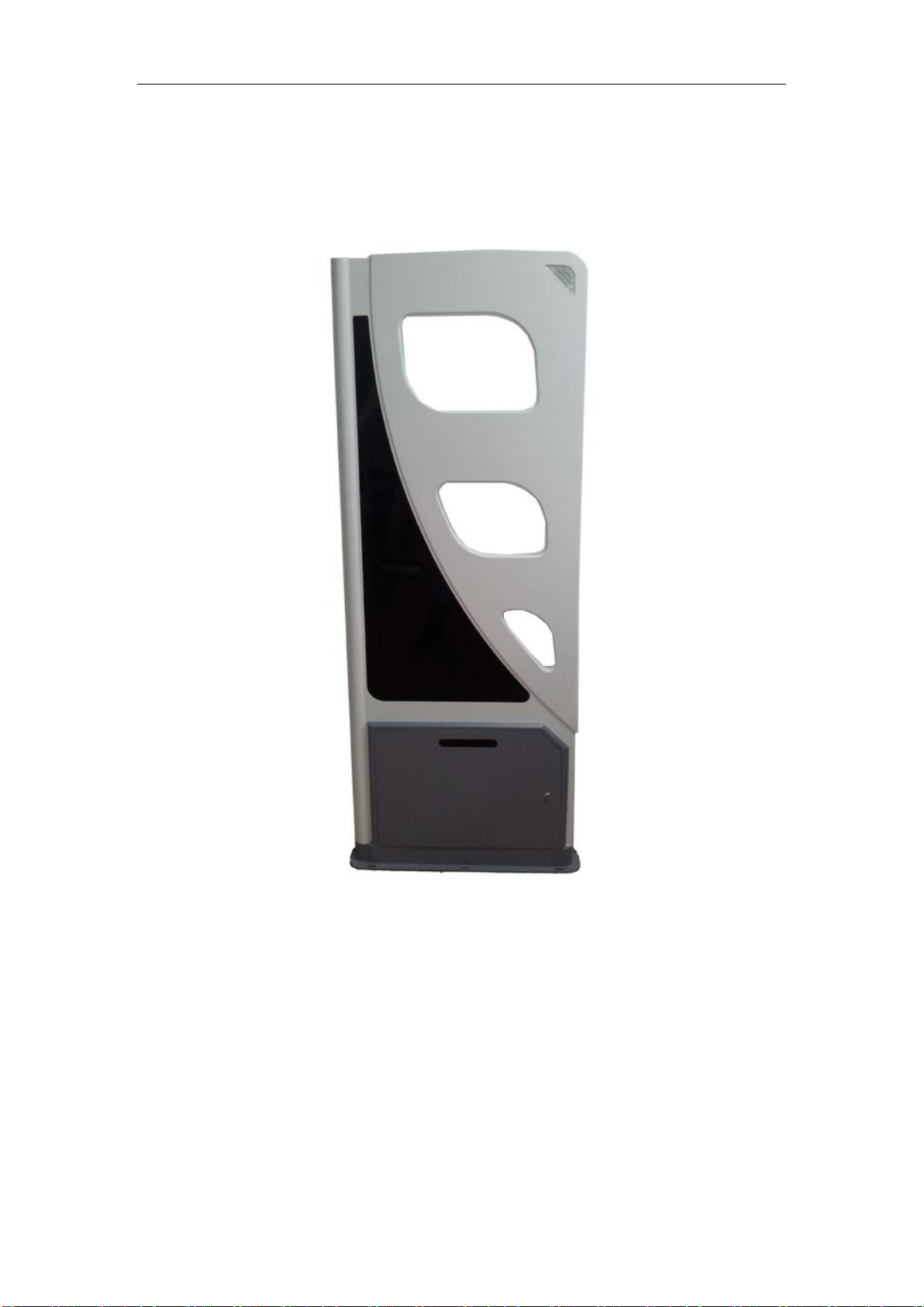
3.1 Device appearance
SR-RH-G3D is as Pic. 2:
HF 3D Gate SR-RH-G3D User’s Manual V1.6
Pic. 2
3.2 Installation regulation
SR-RH-G3D can be used in various ways such as single standalone panel, two
panels (single channel) or synchronized multiple panels (multiple channels).
When installing multiple panels, please make sure to place all panels facing the
same direction like Pic. 3 depicted:

HF 3D Gate SR-RH-G3D User’s Manual V1.6
7
Pic. 3
SR-RH-G3D should be fixed to the ground using screw. The location of the
screws is illustrated as Pic. 4:
Pic. 4
3.3 Cable Connection
SR-RH-G3D uses 4 kinds of cables for normal operation including
synchronizing (SYNC) cable, RF cable, serial communication (UART) cable and AC
power (AC) cable.

HF 3D Gate SR-RH-G3D User’s Manual V1.6
8
1. Cover open
The cover of the device’s base box needs to be opened for cable connection as
following Pic.5:
Pic. 5
The socket arrangement for cable connection is as following Pic.6:
Pic. 6

HF 3D Gate SR-RH-G3D User’s Manual V1.6
9
2. Connect SYNC cable
The SYNC cable is a 4-pin cable as Pic.7. It has 2 functions. The first is
for multiple panels synchronization which is mandatory required for multiple
panel application. The second is for multiple panel network constitution.
Multiple panel synchronization:
SR-RH-G3D uses RS485 communication method for synchronizing data
exchange between various panels. This will take 2 pin in the 4-pin SYNC
cable. For synchronization, the multiple panels need to be cascaded. That
means the output SYNC cable of one panel needs to be connected to input
SYNC port of its following panel as Pic.8. All panels should be cascaded
sequentially in a correct order.
Pic.7
Pic. 8

HF 3D Gate SR-RH-G3D User’s Manual V1.6
10
Multiple panel networking:
Multiple panels can be networked together for facilitating the host to
realize remote management. Multiple panel networking is designed in RS485
way and this will take another 2 pin of the 4-pin SYNC cable.
For multiple panels RS485 networking, the communication switch of each panel
needs to be set to RS485. When the switch is set to RS485, the RS232 port of the
panel will act as a RS232/RS485 converter and the host can easily access to the
RS485 panel network by connecting to panel’s RS232 socket. The addressing of each
panel in the panel RS485 network relies on each panel’s device ID. Please refer to the
following “UART cable connection”.
3. AC Cable Connection
SR-RH-G3D provides two AC power cable socket for cascading connection of
each panels AC power cable. This is useful in practice to make the power supply to
whole system neat and easy to installation. If one panel gets AC power supply at its
AC power-in socket, it can provide AC power for next panel through its AC
power-out socket as Pic.9:

HF 3D Gate SR-RH-G3D User’s Manual V1.6
11
Pic.9
4. RF cable connection
RF cable of each panel should be correctly connected for normal operation. The
RFOUT of one panel should be routed to RFIN of the adjacent following panel to
cascading all panels as Pic.10. The last panel should route its RFOUT to the
dummy 50ohm load embedded in the base box as Pic.11.
Pic.10

12
5. UART Cable Connection
HF 3D Gate SR-RH-G3D User’s Manual V1.6
Pic. 11
Each panel can be individually managed by the host through its RS232 port with
the UART cable connected. To do the work in this way, the communication switch
should be set to RS232 as Pic.12A:
Pic. 12A
When multiple panels have been RS485 networked (the communication switch
of each panel needs to be set to RS485) by SYNC cable, the host can talk with every
panel in the network. In this case, the RS232 port of the panel acts as a
RS232/RS485 converter and the host can easily access to the RS485 panel network

HF 3D Gate SR-RH-G3D User’s Manual V1.6
13
by connecting to any panel’s RS232 socket. The addressing of each panel in the
RS485 panel network relies on each panel’s device ID.
Pic. 12B
3.4 Relay Connection
SR-RH-G3D has 2 embedded relays as Pic.13:
Pic. 13
The 2 relays will be activated when device alarming. The pick-up time can be
configured. NO, COM and NC are relay’s three contact terminal as Normal OPEN,
COMMON and Normal CLOSE.

HF 3D Gate SR-RH-G3D User’s Manual V1.6
14
4 Operation Instructions
SR-RH-G3D should be correctly configured before operation. Users could use
provided configuration software to do this work. The most commonly used
parameter-configuring procedure is carried out through RS232 communication
between the host and the device.
When delivered, the default parameter setting of the device is as list:
Device ID: 0001
Panel SYNC Parameter: Master
Communication Interface: RS232
Baud Rate: 38400 bps
Security Surveillance Parameter: AFI anti-theft
AFI Value: 0x00
Alarm: Buzzing 3 times
Work Mode: Security Surveillance Mode
4.1 Operation Description
The configuration software on the host is designed for Windows OS platform.
User could use this tool software to manage the device, set operation parameters and
get operation results.
4.1.1 Device Parameter Setting
Device parameters (also called system parameters) could be configured in the
tool software’s SYSTEM CONFIGURATION Tab.
Device parameters include:

HF 3D Gate SR-RH-G3D User’s Manual V1.6
15
Device ID: Each panel should have its unique ID number. The adjacent panels’
ID numbers should be interleavedly set to odd or even number. If one panel’s ID
number is even, its adjacent panels ID numbers must be odd.
SYNC Parameter: Set the panel as Master or Slave. Among all cascaded panels,
only one panel can be set as Master and all others should be set as slaves. Generally
the most outside panel will be set as the Master.
Baud Rate: Default baud rate is 38400. It can be set to 9600, 19200, 38400,
57600 or 115200.
Alarm Pattern: Set the buzzer beeping times when alarming. It can be set from
0 to 3. The device will be silent when alarm pattern parameter set to 0. That means
the buzzer will no beep and the alarm light will not flash either.
Security Surveillance: Three anti-theft modes are supported. They are AFI
anti-theft, EAS anti-theft and AFI/EAS mixed anti-theft.
AFI Value: Set the AFI value the device used when in AFI anti-theft security
surveillance mode. 0x00 is broadcasting value and all tags will answer.
Work Mode:the device supports 2 work modes as Security Surveillance mode
and Answer mode. In Security Surveillance mode, the device supports AFI anti-theft,
EAS anti-theft or AFI/EAS mixed anti-theft operation. In Answer mode, the device
will not autonomously work. The device will wait the command from the host and
feedback results after command execution. The Answer mode is major used for tag
read/write operation.

HF 3D Gate SR-RH-G3D User’s Manual V1.6
16
Relay Pick-up Time: It defines the relay pick-up time when the device alarming.
The time ranges from 0.1s~25.5s with 0.1s unit. Default time is 3s.
4.1.2 Tag Operation
Tag operation could be carried out in tool software’s “Tag Operation” tab. The
device supports tag inventory, read, write and other operations.
4.1.3 Statistical Information
User could use tool software to acquire or clean some statistical information such
as alarming times counting and people counting.
4.2 Operation Procedure
Users should refer to the following typical installation and configuration
procedure in device application:
1. Installation
Refer to the former corresponding chapter of this manual to correctly install the
gate device and connect all necessary cables. The commonly-used channel width is
around 90cm.
2. Configuration
◆ The simplest way to configure the panel is configuring it one by one through
its RS232 port. All panels can also be RS485 networked together for centralized
management. Users can try this advanced operation when familiar with the whole
device. The following example illustration is based on single panel individual
operation through RS232.

HF 3D Gate SR-RH-G3D User’s Manual V1.6
17
◆ Running configuration tool software on the host and the main GUI is as
Pic.14:
Pic. 14
◆ Input device ID in the “Device ID”. The default device ID is 0001. Broadcast
address “FFFF” can also be used in this single panel case.
Click “Open” button, the current using parameter will be showed as Pic.15:

HF 3D Gate SR-RH-G3D User’s Manual V1.6
18
Pic.15
◆Set Parameters: Set Device ID, SYNC parameter, AFI value, baud rate,
anti-theft mode, work mode and so on.
◆Save parameters: Save your configuration parameters into device’s
non-volatile memory. All the parameters will remain unchanged until next
configuration. If saved parameters corrupt, the default value will be used instead.
3. Statistical Information
User could use tool software to acquire or clean some statistical information such
as alarming times counting and people counting.
The statistical information tab is as Pic.16:

HF 3D Gate SR-RH-G3D User’s Manual V1.6
19
Pic.16
Select “RS232 Query”:
◆The communication switch should be at RS232 position;
◆Press Start Query button to get statistical information;
When the host need to access a panel in a RS485 networked multiple panels
environment, please select “RS485 Query”:
◆The communication switch should be at RS485 position;
◆ Add all device IDs to the text box. The software will poll and retrieve each
panel’s information one by one;
◆ Choose the information to be acquired, press “Start Query” button and all the
information will be displayed on the right column.

HF 3D Gate SR-RH-G3D User’s Manual V1.6
20
4. Additional parameter
The parameters in this tab are mainly used to set some work parameters for the
HF High Power RFID Reader embedded in the device. Users should let it
unchanged as its default value in most cases.
Default values are:
Power: 23 (6W)
Parse mode: DPPM 100%

21
5 Technical Parameter
Electric Parameter
Frequency
13.56MHz±7KHz
Protocol
ISO/IEC 15693
Effective Gate
Width
≥90cm (depends on tag and working
environment)
Interface
RS232/RS485
Supply Voltage
100~240VAC 50/60Hz
Power
Dissipation
<20W
RF power
>3W
RF Output
Impedance
50Ω
Infrared Sensor
2 lines
Environment
Parameter
Work
Temperature
-25℃~60℃
Storage
Temperature
-40℃~85℃
Relative humidity
30%~95% RH
Physical Parameter
Dimension
L*W 170*62cm
T 3.5cm(upper)
6cm (box)
11cm (base)
Weight
30Kg
Color
Light grey
Material
ABS
HF 3D Gate SR-RH-G3D User’s Manual V1.6
6 Troubleshooting
(1) Q: The com. Port of demo software cannot be open.
A: If the device is connected to the system through RS232 interface, please check if

HF 3D Gate SR-RH-G3D User’s Manual V1.6
22
the RS232 cable is connected correctly; if the device is connected to the system
through RS485 interface, please check if the RS485 SYNC cable is connected to
the device correctly. In addition, please remember to input device ID before
opening the port. When using RS232 interface, if the device ID can not be
confirmed, please input “FFFF” broadcast address instead.
(2)Q: RS485 SYNC cable connecting method
A: Adopt cascading method. For example: RS485 SYNC output of the first panel will
be connected to RS485 SYNC input of the second panel, RS485 SYNC output of
second panel will be connected to RS485 SYNC input of the third panel and so on.
(3)Q: When a tag passes the gate, the alarm light flashes but the buzzer no
beeping.
A: The buzzer is adjusted to be silent. Please increase the volume using
volume-adjusting button of the panel or the configuration software on the host.
(4)When a tag passing, there is no alarm.
A: Check if the device has been set to be silent;
Check if the cables are connected correctly and only one panel has been set to
Master;
Check if the device is in security surveillance mode and if the current security
surveillance anti-theft mode matches the tag function. For example, if the device is set
to AFI anti-theft mode, please check if the AFI value of the tag is the same as the one
set in the device; if the device is set to EAS anti-theft mode, check if the EAS bit has
been set to active in the tag.

HF 3D Gate SR-RH-G3D User’s Manual V1.6
23
(5)why do some panels show a longer effective distance than other panels?
A: The possible reasons are: 2 or more panels are set as Master among all the
cascading panels. Please make sure that only one panel is set to Master.
7 Remarks
A. Support on-the-site firmware upgrading, further development and
customization.
B. Please contact us if encountering any problem.

HF 3D Gate SR-RH-G3D User’s Manual V1.6
24
FCC Caution.
This device complies with part 15 of the FCC Rules. Operation is subject to the
following two conditions: (1) This device may not cause harmful interference, and (2)
this device must accept any interference received, including interference that may
cause undesired operation.
Any Changes or modifications not expressly approved by the party responsible for
compliance could void the user's authority to operate the equipment.
Note: This equipment has been tested and found to comply with the limits for a Class
B digital device, pursuant to part 15 of the FCC Rules. These limits are designed to
provide reasonable protection against harmful interference in a residential installation.
This equipment generates uses and can radiate radio frequency energy and, if not
installed and used in accordance with the instructions, may cause harmful interference
to radio communications. However, there is no guarantee that interference will not
occur in a particular installation. If this equipment does cause harmful interference to
radio or television reception, which can be determined by turning the equipment off
and on, the user is encouraged to try to correct the interference by one or more of the
following measures:
-Reorient or relocate the receiving antenna.
-Increase the separation between theequipment and receiver.
-Connect the equipment into an outlet on a circuit different from that to which the
receiver is connected.
-Consult the dealer or an experienced radio/TV technician for help.
IC Caution.
This device complies with Industry Canada licence-exempt RSS standard(s).
Operation is subject to the following two conditions: (1) This device may not cause
interference, and (2) This device must accept any interference, including interference
that may cause undesired operation of the device.
Le présentappareilestconforme aux CNR d'Industrie Canada applicables aux appareils
radio exempts de licence. L'exploitationestautorisée aux deux conditions suivantes:
(1) l'appareil ne doit pas produire de brouillage, et
(2) l'utilisateur de l'appareildoit accepter tout brouillageradioélectriquesubi, mêmesi le
brouillageest susceptible d'encompromettre le fonctionnement.
This Class [B] digital apparatus complies with Canadian ICES-003.
Cet appareil numérique de la classe [B] est conforme à la norme NMB-003 du
Canada.
 Loading...