


User Manual
IA9Q5 S83F
RF 5G Wireless Module
1
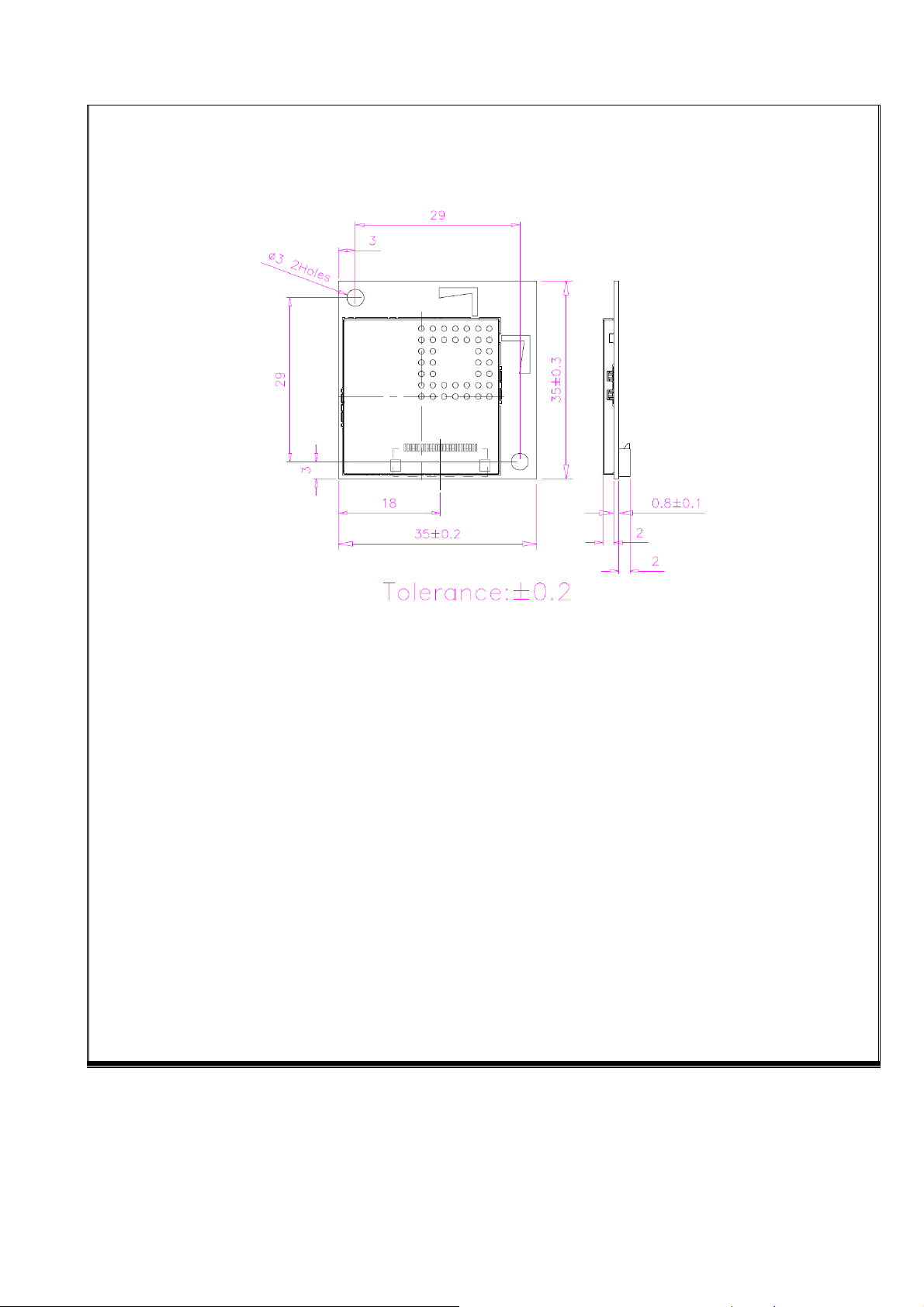
1. Appearance & Dimension
Dimension:35 * 35 * 0.8 mm
Mechanical Drawing:
2
2. Mechanical & Key Connector
2.1 PCB Board Material
Type:FR-4,Surface finish:ENIG,Layers:4。Dimension:35 * 35 * 0.8 mm;
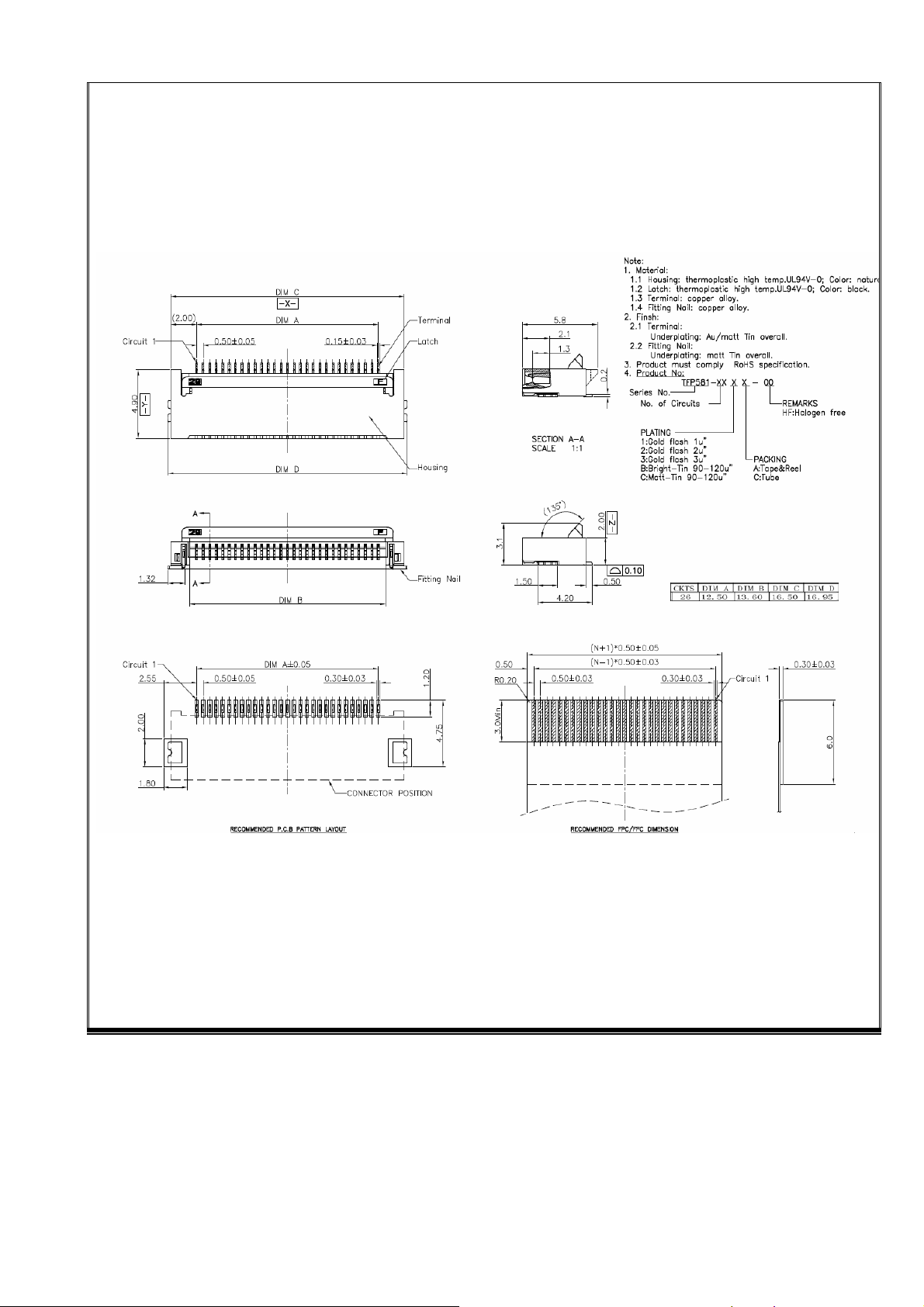
2.2 FFC Connector
3
3. Performance
3.1 RF Specification
Standard
Connector Type FPC connector 26 Pin
Transceiver mode
Modulation GFSK
Frequency range
Output Power
Sensitivity -90dBm(The smaller, the better)
Input Voltage 3.0~3.6V (3.3V TYP.)
Power
consumption
Antenna Type Dual PCB Routing on board
Wireless 5G Proprietary Protocol
1T1R
5.165 ~ 5.200 GHz (option)
5.740 ~ 5.840 GHz
12dBm (
Consumption Current (TX_MODE):100 mA
Consumption Current (RX_MODE):65 mA
Peak power at Antenna port
)
4

3.2 Antenna Specification
Impedance Input impedance 50 ohm
Frequency 5.135GHz~5.205GHz,5.740~5.840GHz
VSWR 5.135GHz~5.205GHz , 1.46 ; 5.740~5.840GHz , 2.02
R.L 5.135GHz~5.205GHz:RL≤-14.5dB,5.15~5.85GHz:RL≤-9.4dB
Isolation
Gain Omni-direction,Peak Gain ≤ 2.85dBi
ANT0 VS ANT1 ≤-15dB
The antennas didn’t operate simultaneous.
3.4 GPIO Pin define
5
4 Reliability Test
NO Test Item Test condition Test result
a) Power on
b) Vin = working voltage
c) -10℃ to 60℃
d) Duration of exposure –10℃ & 60℃ at
1
2
3
TCT
(Operating)
LTST
(Operating)
HTST
(Operating)
least 5mins.
e) Ramp rate 2.3 ℃/mins or less.
f) Power on/off 2,000 times (applicable to
new module project with EEPROM or
ECN related to EEPROM.)
g) 30 cycles, samples: 6pcs
a) Power on.
b) Vin = working voltage
c) Operation at –10℃.
d) 72hrs, samples: 6pcs
a) Power on.
b) Vin = working voltage
c) Operation at 60℃.
d) 72hrs, samples: 6pcs
Pass
Pass
Pass
a) Power on.
4
5
6
7
8
THB
(Operating)
HTOL
(Operating)
TST
(Storage)
LTST
(Storage)
HTST
(Storage)
b) Vin = working voltage
c) Operation at 40℃/90%RH~95%RH.
d) 72hrs, samples: 6pcs
a) Just Power on Module,No Pairing with RX
b) Vin = working voltage
c) Operation at 85℃
d) 96hrs, samples:50pcs
a) No DC input to Module
b) -10℃ to 60℃, Ramp rate 5℃/mins or less
c) Duration of exposure at least 5mins.
d) 30 cycles, samples: 22pcs
a) No DC input to Module
b) Storage Temp: -20℃
c) 300hrs, samples: 22pcs
a) No DC input to Module
b) Storage Temp: +85℃
c) 300hrs, samples: 22pcs
Pass
Pass
Pass
Pass
Pass
6

9
10
THT
Packing
VIBRATION
a) No DC input to Module
b) 40℃, 90%RH~95%RH
c) 72hrs, samples: 22pcs
a) Sinusoidal, 3g, 5~500Hz, 1hrs/a xi s
b) Random, 3g, 5~500Hz, 0.5hrs/axis
c) Number of cycles:3 cycles for each axis
d) Vibration axis:X, Y and Z
e) samples:6pcs
Pass
Pass
11
Packing
Drop Test
a) Height: 92cm (or more) dropped, 1corner, 3 edges,
6 faces. (Total: 10 drops)
b) Samples: 6pcs
Pass
7

5. Features
a. 5.2GHz/5.8GHz ISM Band
b. GFSK modulation
c. Low BOM cost
d. Long distance > 30m (Line of sight)
e. Support 1-1 duplex mode or 1-N broadcasting mode
f. RF frequency hopping in 58 channels
g. Digital I2S audio interface
h. Support no audio detection function
i. Audio format 24bit , 32/44.1/48KHz sampling rate
j. Robust Packet error correction
k. Low power consumption
l. No RF induced audio noise
m. Compatible with FCC/ CE regulations
6. Application
a. Wireless HTiB Rear Speaker
b. Wireless Outdoor Speaker
c. Wireless TV theater
d. Wireless Audio Sender
e. Wireless Headphone & Wireless Stereo Ear Microphone
8

7. Statement
a. CE Statement
Herby, Syncomm Technology Corp. declares that this RF 5G Wireless Module ,IA9Q5 S83F is in
compliance with the essential requirements and other relevant provisions of Directive 2014/53/EU.
1.) Operation limit:Use the RF 5G Wireless Module in the environment with the temperature between
0℃ and 55℃(Temp.),
2.) Operation Frequency range: 5740MHz-5840 MHz
5740MHz-5840 MHz can be used can be used in Europe without restriction.
3.) RF Output Power: 9.81dBm
MANUFACTURER INFORMATION:
Manufacturer:Syncomm Technology Corp.
Address:10F., No.101, Sec.2 Gongdao 5th Rd., Hsinchu City, 30070 Taiwan
Tel: 886-3-5169188
Fax: 886-3-51691 11
E-mail: cf.liu@syncomm.com.tw
b. FCC Statement
Changes or modifications not expressly approved by the party responsible for compliance could void
the user's authority to operate the equipment.
This equipment has been tested and found to comply with the limits for a Class B digital device,
pursuant to Part 15 of the FCC Rules. These limits are designed to provide reasonable protection
against harmful interference in a residential installation. This equipment generates uses and can
radiate radio frequency energy and, if not installed and used in accordance with the instructions, may
cause harmful interference to radio communications. However, there is no guarantee that interference
will not occur in a particular installation. If this equipment does cause harmful interference to radio or
television reception, which can be determined by turning the equipment off and on, the user is
encouraged to try to correct the interference by one or more of the following measures:
-- Reorient or relocate the receiving antenna.
-- Increase the separation between the equipment and receiver.
-- Connect the equipment into an outlet on a circuit different from that to which the receiver is
connected.
-- Consult the dealer or an experienced radio/TV technician for help
This device complies with part 15 of the FCC rules. Operation is subject to the following two conditions
(1)this device may not cause harmful interference, and (2) this device must accept any interference
received, including interference that may cause undesired operation.
9
 Loading...