

Synapse SNAP Link, SNAP Link SL232K-001, SNAP Link SL232M-001, SNAP Link SL485K-001, SNAP Link SL485M-001 User Manual
Page 1

SNAP Link
Serial Wireless Adapter
User Guide
Wireless Technology to Control and
Monitor Anything from Anywhere ™
Synapse Wireless, Inc.
500 Discovery Drive
Huntsville, Alabama 35806
256.852.7888
www.synapse-wireless.com
Document Number 600038-01C
Contents SNAP Link User Guide
Page 2

These devices comply with part 15 of the FCC rules. Operation is subject to the
following two conditions: (1) These devices may not cause harmful interference, and
(2) These devices must accept any interference received, including interference that
may cause harmful operation.
Please refer to the full FCC and IC statements found in the appendix at the end of
this user guide.
Copyright © 2010 Synapse Wireless, Inc., All Rights Reserved.
All Synapse products are patent pending.
Synapse logo, SNAP, and Portal are all registered trademarks of
Synapse Wireless, Inc.
500 Discovery Drive
Huntsville, Alabama 35806
256.852.7888
Contents SNAP Link User Guide
Page 3

Contents
SNAP Link Se ri al Wireless Adapter U s e r G u i d e
Contents 3
About Your SNAP Link Wireless Adapters 1
SNAP Link Adapters 1
Key Features of SNAP Link 1
Document Conventions 2
Download Supporting Materials 2
Setting Up Your SNAP Link Wireless Adapters 3
Modes of Operation 3
SNAP Link State Indicators 3
Changing SNAP Link States 4
Pin Outs 5
RS-232 (DB9F) Pin Outs 5
RS-485/422 Pin Outs 6
SNAP Link EasySet Software 7
Installing EasySet 7
Using EasySet 9
Toolbar 9
Connect a SNAP Link Device 10
Tab Bar 10
Selecting Basic Communications Settings 11
UART Settings 18
Pairing Settings 20
Contents SNAP Link User Guide
Page 4

Advanced Settings 21
Configuring your Adaptor using the DIP Switches 22
DIP Switch 1 23
DIP Switch 2 25
Application Usage Scenarios 26
Scenario 1: Card Scanner 26
Scenario 2: File Transfer, Continuous Stream 27
Scenario 3: Lowest Latency at Highest Baud Rate 27
Troubleshooting 28
Signal Strength Problems 28
Multiple Masters 28
Can’t Find a Master 29
Poor Performance 29
Paired but not Communicating 29
Frequently Asked Questions 30
Appendices 32
Mounting Options 32
Modbus Firmware 33
Advanced Management 35
Specifications 35
General 35
Power Requirements 35
Physical Properties 36
RF (Wireless) Properties 36
Antenna 37
Certifications 37
RS-232 37
Contents SNAP Link User Guide
Page 5

RS-485/422 38
Software 38
Regulatory Information and Certifications 38
RF exposure statement 38
FCC certifications and regulatory information (USA only) 38
Modifications (FCC 15.21) 39
Declaration of Conformity 39
Industry Canada (IC) certifications 40
Contents SNAP Link User Guide
Page 6

Page 7

About Your SNAP Link Wireless
SL232 SL485
Adapters
SNAP Link Adapters
The SNAP Link family of industrial-class, mesh networking, wireless serial adapters allows you to connect
RS-232 and RS-485/422 devices to each other without using cables.
SNAP Link adapters provide the highest data-rates, longest distance, and
most reliable signal in the industry.
SNAP Link devices are available in four models:
‣ SL232K-001 – RS-232 with 250 Kbps wireless data rate
‣ SL232M-001 – RS-232 with 2 Mbps wireless data rate
(available first quarter 2011)
‣ SL485K-001 – RS-485/422 with 250 Kbps wireless data rate
‣ SL485M-001 – RS-485/422 with 2 Mbps wireless data rate
(available first quarter 2011)
Each SNAP Link adapter comes with SNAP EasySet, an intuitive application program that runs on
Microsoft® Windows®-based computers that allows you to configure the device quickly and easily. Please
refer to software specifications in the appendix of this document for exact operating system requirements.
You can also configure your SNAP Link adapters using internal DIP switches in the event a computer
running EasySet is not available.
Key Features of SNAP Link
‣ Features SNAP® — the Synapse Network Application Protocol — instant-on, self-healing, mesh
network operating system.
‣ Available with wireless data rates up to 2 Mbps.
‣ Supports wireless RS-232, RS-422, and RS-485 transparent serial data transfers.
‣ Hardened Modbus wireless protocol included for 99.5% reliable transport.
‣ Enables simple, one button pairing for fast, easy installation.
‣ Supports one-to-one (point-to-point) and one-to-many (multipoint) relationships.
‣ Performs mesh hopping, which can extend distances across many miles.
About Your SNAP Link Wireless Adapters SNAP Link User Guide 1
Page 8

‣ Includes SNAP Link EasySet software for advanced configurations.
‣ Requires no changes to existing equipment and software.
Document Conventions
Please note the following terminology while reading this document:
‣ The term SNAP Link is used to refer to any of the SNAP Link models listed above.
‣ The RS-232 models are referred to by their model number, which is SL232. This pertains to both
models unless otherwise noted.
‣ The RS-485/422 models are referred to by their model number, which is SL485. This pertains to both
models unless otherwise noted.
‣ The term K-series refers to the SL232K and SL485K adapters.
‣ The term M-series refers to the SL232M and SL485M adapters. The distinguishing characteristic
differentiating K-series and M-series devices is their wireless transmission speed.
‣ The term serial port refers to the data communications port – either the RS-232 port (DB9F
connector) of an SL232 device or the RS-485/422 terminal block of an SL485 device.
‣ The micro-B USB port of the SNAP Link adapter may be referred to as simply the USB port.
‣ The term RS-485/422 device or RS-232 device refers to the data communications device you are
attaching to the SNAP Link adapter.
‣ The term UART Parameter refers to SNAP Link configuration settings that indicate how quickly data
is wirelessly transmitted based on serial data that is received from the serial device.
‣ The term, Modbus Firmware, refers to a Modbus protocol reliability script that can be uploaded to a
SNAP Link model using EasySet software V1.2.2 or higher.
Download Supporting Materials
Documentation pertaining to SNAP Link devices can be downloaded from the Synapse Wireless website at:
synapse-wireless.com/index.php?mainID=3&subID=11&type=product&prodID=11
The SNAP Link User Guide (the document you are reading now) can be downloaded at:
synapse-wireless.com/documents/products/SNAP_Link_User_Guide.pdf
The Synapse SNAP EasySet configuration software can be downloaded at:
synapse-wireless.com/documents/apps/EasySet-setup.exe
About Your SNAP Link Wireless Adapters SNAP Link User Guide 2
Page 9

Setting Up Your SNAP Link
Wireless Adapters
Refer to your SNAP Link Quick Start Guide accompanying your SNAP Link wireless adapter for
illustrations showing you how to set it up quickly. This chapter gives you more detail about the various
modes of operation and the three indicator lights.
Modes of Operation
SNAP Link units are powered via a USB cable through their micro-B USB connector. They can be powered
by connecting a USB cable to the supplied AC adapter, or by plugging the cable into the USB port of a
computer. It will be necessary to use a computer’s USB port if you wish to configure your SNAP Link units
using the EasySet software, which is described in the next chapter.
All models of SNAP Link can operate in either point-to-point mode, also known as unicast, or in multipoint
mode, also known as multicast. In point-to-point mode two SNAP Link units are paired, thereby providing a
wireless connection between two external serial devices. In multipoint mode, one of the SNAP Link devices
is designated the master and multiple other devices can be configured as slaves. This section provides more
detail on how these modes can be set manually by pressing the MODE button on the SNAP Link device.
SNAP Link State Indicators
You can change the state of your adapter either by holding down the MODE button or by pressing it in rapid
succession.
There are three LEDs on a SNAP Link device. LED A is located on the front next to the MODE button.
LEDs B and C are located on the back panel between the micro-B USB and serial connectors.
Set from the factory, these three LEDs communicate various configuration settings or traffic status events as
documented next, unless the Modbus firmware script has been uploaded to the SNAP Link adapter.
Note: The three LEDs perform differently when the Modbus hardened reliability firmware has been
installed, as documented in the Modbus Firmware Appendix
The A LED indicates the wireless broadcast state. It can be off, green, amber or red, and can be steady or
flashing depending upon the current status or mode of operation:
‣ When the unit is seeking a pair the LED will rapidly flash red.
‣ When the unit is paired, either in unicast mode or as a slave in multicast mode, the LED will glow
steadily. Green indicates a strong wireless signal, amber indicates a weak signal, and red indicates no
signal or loss of signal from its partner. No matter what the color, the LED will flicker while wireless
transmission is occurring.
‣ When the unit is in multipoint mode and is seeking a master, the LED will rapidly flash amber.
‣ When the unit is set up as a master, the LED will slowly alternate between green and amber.
Setting Up Your SNAP Link Wireless Adapters SNAP Link User Guide 3
Page 10

‣ If a master detects another master on the same channel and network, the LED will slowly alternate
Reset a unit, or return it to
broadcast state
Broadcast state is the initial SNAP Link state as set by the factory. To
return to broadcast state, remove power, hold down the MODE
button, then reapply power. After 5 seconds, when all LEDs are
rapidly flashing green-amber-red, release the MODE button. The B
LED will be green, signifying power. The C LED will be green only
if an RS-232 device is attached. The A LED, which signifies
broadcast state, will be off.
Pair a unit in point-to-point
While in broadcast state, hold down the MODE button for at least 5
seconds. When LED A turns red, release the MODE button. The unit
will then look for another SNAP Link to pair with, as indicated by the
LED rapidly flashing red. When it finds a partner, the A LED will
glow steadily. Green indicates a strong signal from the partner, amber
indicates a weak signal, and red indicates no signal (the partner is
powered off or else is out of range).
Note: a SNAP Link adapter will only pair with another adapter that is
also seeking a pair. So you must perform the above procedure on two
SNAP Link adapters simultaneously to form a pairing.
Back out of searching for a pair
While LED A is rapidly flashing red, hold down the MODE button
for at least 5 seconds. LED A should go dark. Release the MODE
button and the unit is now back in broadcast state.
between red and amber.
The B LED indicates the USB state. Green indicates the unit is being supplied with power. It will glow
steadily in idle and will flicker when data is being transferred via the USB port.
The C LED indicates the serial interface state. If an RS-232 device is attached to the DB9F connector of the
SL232 adapter, the LED will glow steadily green in idle and will flicker as data is being transferred. If an RS484/422 device is attached to the terminal bock of the SL485 adapter, the LED will not glow, but will flicker
as data is being transferred.
Note: It may be difficult to differentiate an amber colored LED from one showing green or red, depending
upon your viewing angle. When viewed from above, an amber LED may look red and when viewed
from below it might look green. If in doubt, try viewing the LED at different angles.
Changing SNAP Link States
When a SNAP Link device is initially powered on, its serial communications parameters are set to factory
defaults. This initial state is called broadcast state, because at this point SNAP Link hasn’t been paired with
another unit. However, it will join and become a member of a greater SNAP mesh network. Most commonly,
each SNAP Link device will be married to, or paired with, another SNAP Link.
The factory default serial port settings for all SNAP Link devices is 9600 baud, 8 data bits, no parity, and 1
stop bit. For SL232 devices flow control is disabled, and for SL485 devices flow control is always enabled.
The SNAP network ID is set to 0x1C2C and the channel number is set to 4. Many of these can be altered
using EasySet or by using a bank of DIP switches located on the SNAP Link circuit board inside the unit, as
shown in the chapter ―Configuring your Adaptor using the DIP Switches.‖ Resetting a unit causes the SNAP
Link device to read the DIP switches and set itself accordingly.
Setting Up Your SNAP Link Wireless Adapters SNAP Link User Guide 4
Page 11

Remove pairing
Hold down the MODE button for at least 5 seconds. When LED A
turns red, release the MODE button. The unit drop any current pairing
and will then begin looking for another SNAP Link unit with which to
pair.
Set a unit to multipoint mode
While in broadcast state, press the MODE button 4 times in rapid
succession (within 3 seconds). LED A will rapidly flash amber. The
unit is now in multipoint mode and will begin looking for a master to
pair with. If it finds one, it will pair with it and the A LED will glow
steady, but will flicker as data is transmitted.
Set up a unit as a multipoint
master
While in multipoint mode, again press the MODE button 4 times in
rapid succession. LED A will then blink slowly, alternating between
green and amber, indicating the unit is the master in a multipoint
network. Any slave units on the same channel and with the same
network ID, which were previously set to multipoint mode, will then
begin pairing with the master. If LED A should begin alternating
between red and amber, that indicates another master is already on the
same channel and with the same network ID.
Back out of multipoint mode
when previously set up as a
master
If the unit was previously set up as a master, press and hold the
MODE button (for at least 5 seconds) until LED A rapidly flashes.
The unit is no longer a master, but is still in multipoint mode, and is
now looking for a master with which to pair.
Back out of multipoint mode
altogether
If the unit was previously set up as a master, first back out by
following the procedure above. Then, press and hold the MODE
button again (for at least 5 seconds) until LED A glows steadily.
Release and the unit is now back in broadcast state. It can now be set
up in point-to-point mode or in multipoint mode.
Pin Outs
RS-232 PIN OUTS
Arrows indicate signal direction
RS-232 (DB9F) Pin Outs
The SL232 adapter provides a DB9 female connector with the following pin outs:
Setting Up Your SNAP Link Wireless Adapters SNAP Link User Guide 5
Page 12

The SL232 adapter uses a standard DB9 female connector configured as a DCE (Data Communications
TWO-WIRE MODE
FOUR-WIRE MODE
Equipment) device. A DCE device can be connected to a DTE (Data Terminal Equipment) device using a
straight through serial cable. A computer is typically defined as a DTE and communications peripherals, such
as the SL232, are defined as a DCE. To connect a DCE with another DCE, or DTE to another DTE, a null
modem adapter, or crossover cable, is required. The null modem adapter swaps certain pins, typically pins 2
and 3, and 7 and 8, to convert a DCE into a DTE and vice-versa.
RS-485/422 Pin Outs
The SL485 adapter can operate in either 2-wire mode or 4-wire mode according to the following pin outs:
A terminal block is provided to which the transmit (TX), receive (RX), and ground (GND) wires can be
attached. The factory default is set to 2-wire, but can be changed using the DIP switches located on the circuit
board inside the adapter case. See the chapter ―Configuring your Adaptor using the DIP Switches‖ for details
in setting the DIP switches.
To wire a connection in two-wire mode, pick a pair of TX/RX pins – either 1 and 2 or 3 and 4. If your
application requires a ground wire, sometimes referred to as 3-wire or 5-wire, then also include pin 5.
Setting Up Your SNAP Link Wireless Adapters SNAP Link User Guide 6
Page 13

SNAP Link EasySet Software
Upon launching the installer, this
dialog is presented.
Synapse has developed an intuitive software application to help you configure your SNAP Link adapter. This
software, known as SNAP EasySet, provides a graphical interface to access settings such as baud rate, flow
control, and parity bits.
EasySet is currently available for Microsoft Windows XP (SP2) or newer and Windows 7 operating systems,
and can be downloaded from the Synapse Wireless website at:
synapse-wireless.com/documents/apps/EasySet-setup.exe
After downloading the software launch the installer to guide you through the installation process.
Installing EasySet
SNAP Link EasySet Software SNAP Link User Guide 7
Page 14

Click Next to continue and follow
the on screen installation
instructions. First specify where
EasySet should be installed, the
default being the Synapse folder
within Program Files. Then press
Install and the software will be
installed to the specified location.
This dialog gives you the option
to exclude certain components.
During installation you’re asked
to disconnect any Synapse USB
devices. This is so the installer
can load new drivers.
Disconnect any Synapse USB
devices and press Ok to
complete the installation.
SNAP Link EasySet Software SNAP Link User Guide 8
Page 15
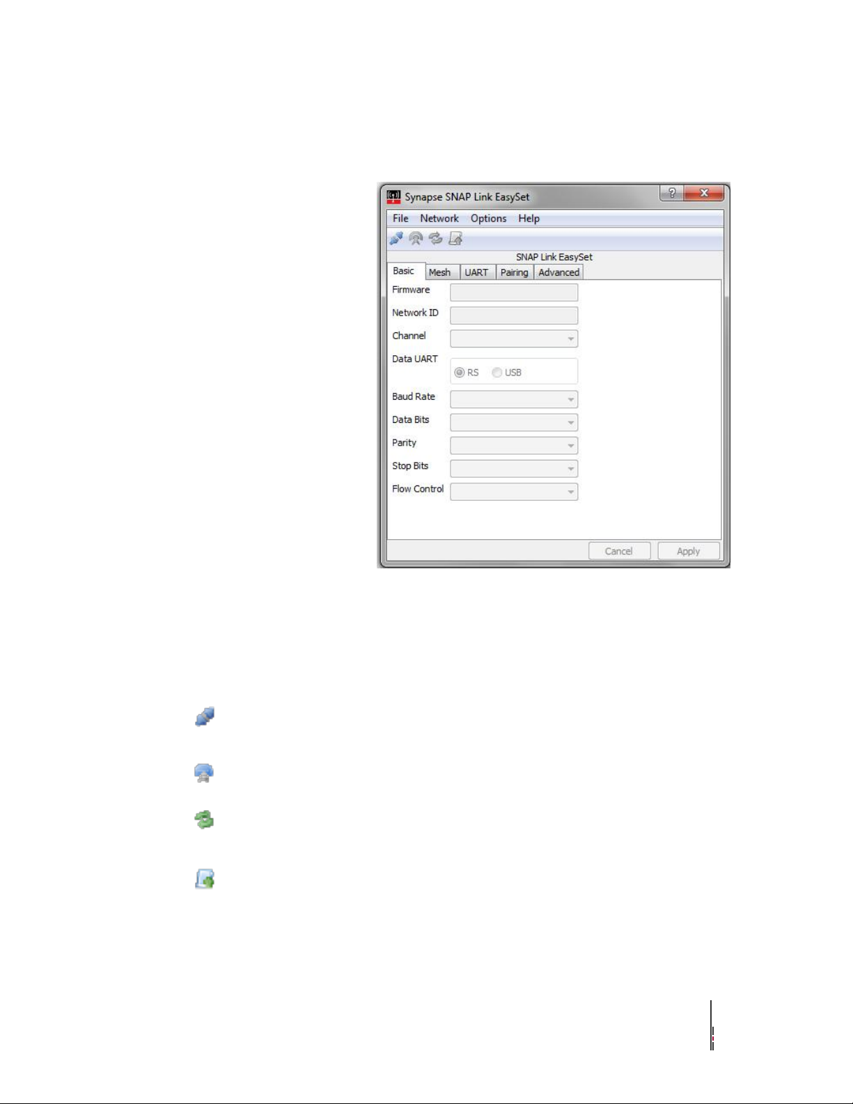
Using EasySet
Launch EasySet by selecting
EasySet from the Windows Start
menu. EasySet will start up and
present this window.
You will see four icons in the
tool bar across the top of the
window. Most of these are
inactive (grayed out) until
EasySet is connected with a
SNAP Link adapter.
There are also four tabs in a tab
bar below the tool bar.
Connect / Disconnect Serial Port – used to connect and disconnect from the attached SNAP Link
device. Because this icon changes when you connect or disconnect, it also serves as a quick
status indicator.
Ping – causes EasySet to make a quick connectivity test to the attached SNAP Link device.
Refresh Node Information – causes EasySet to poll the attached SNAP Link device for
configuration information.
Upload SNAPpy Image – prompts EasySet to upload the SNAP Link operating software into the
attached SNAP Link device. It will be necessary to do this only upon release of new SNAP Link
software, or upon instruction by technical support.
Toolbar
The four toolbar commands are:
SNAP Link EasySet Software SNAP Link User Guide 9
Page 16
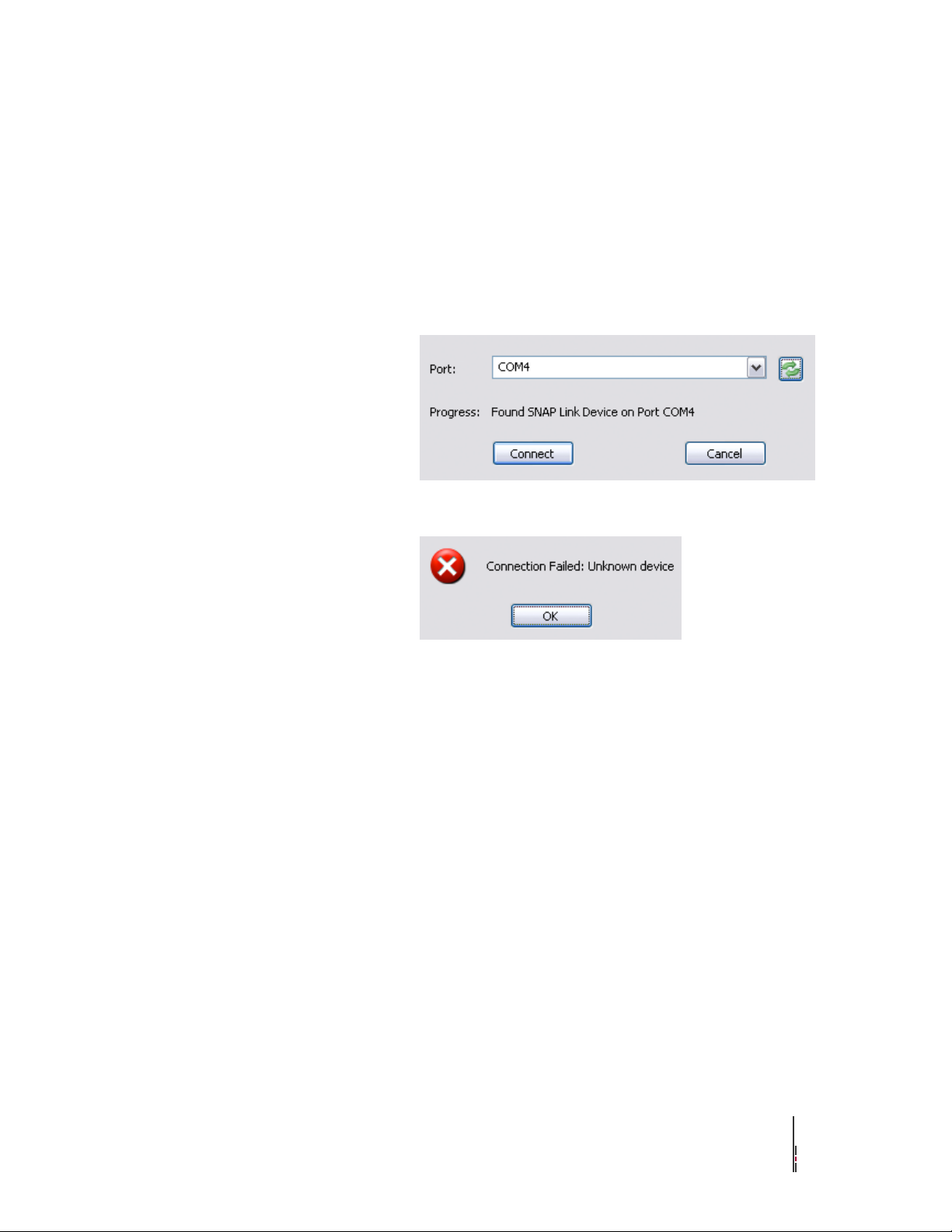
Connect a SNAP Link Device
When EasySet finds a Synapse
device, press the Connect button.
If it failed to find the correct
device type, press the Scan
button to the right of the port
identifier. This will cause
EasySet to continue the scan.
If EasySet finds an attached
device, but it’s not a SNAP Link,
then you will see this error
message. Press Ok and then Scan
again.
Connect a SNAP Link device to your computer using the supplied USB cable. The micro-B side of the cable
fits into the back of the SNAP Link device and the USB end fits into any standard USB port on your PC. This
connection supplies power to the SNAP Link and also allows EasySet to communicate with it.
Next, tell EasySet to scan the computer’s communications ports for a Synapse device. Press the Connect
Serial Port button and EasySet will scan all serial ports and will stop when it believes it has found a SNAP
Link device.
When successfully connected to a SNAP Link device, EasySet populates the communication fields with the
data currently set in the SNAP Link device.
When the SNAP Link device is powered up for the first time, you will see the factory default settings set
internally by the DIP switches. Once the configuration is changed by EasySet, the SNAP Link device will
retain the new configuration in flash memory.
Tab Bar
There are four tabs across the top of the window – Basic, UART, Pairing, and Advanced – which allow you
to match the communications settings of your SNAP Link adapter to that of the serial communications device
to which you are connecting.
SNAP Link EasySet Software SNAP Link User Guide 10
Page 17
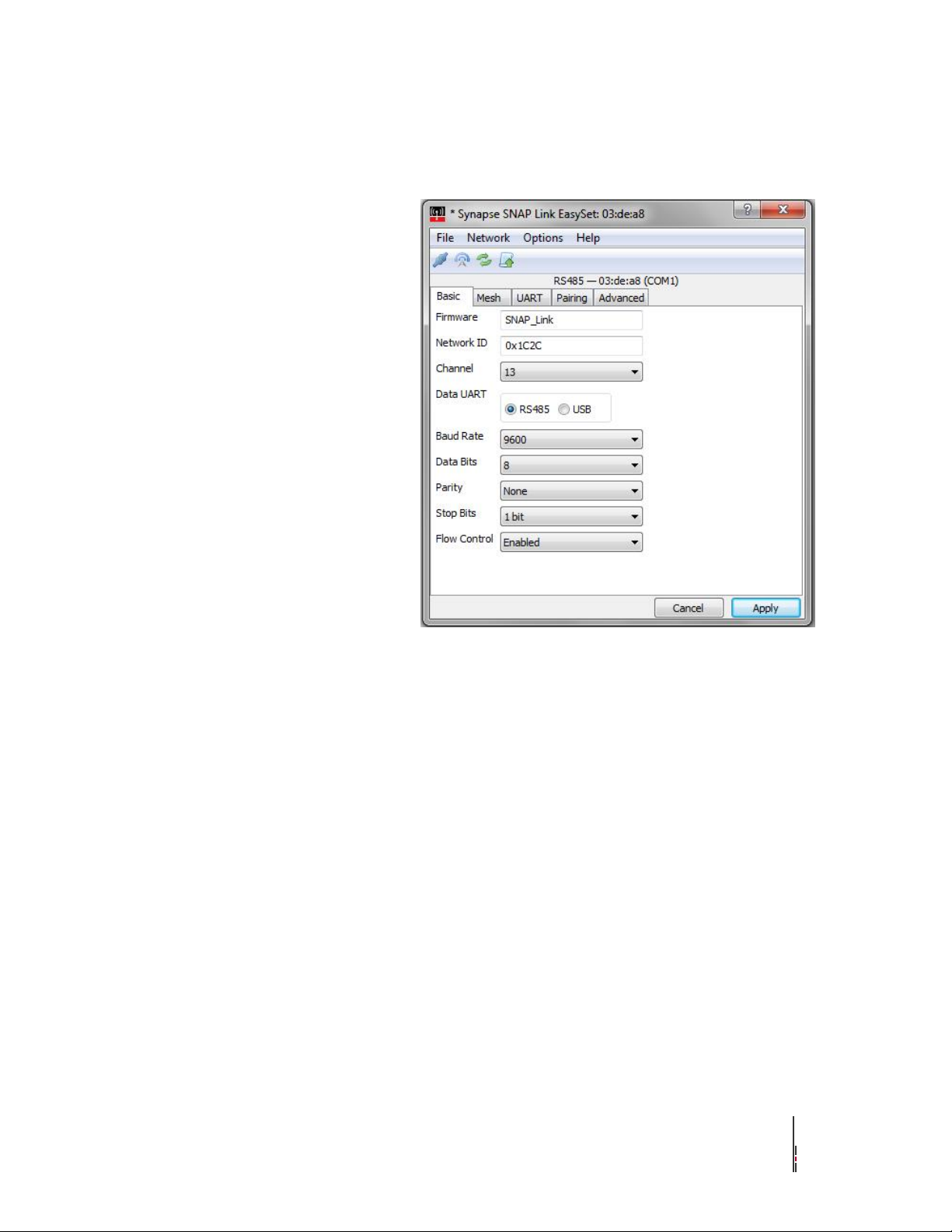
Selecting Basic Communications Settings
Below the icons and immediately
above the tab bar is the SNAP
Link adapter type: either RS-232
or RS-485/422. To the right of
that is the adapter’s MAC (media
access control) address. The
same address is also printed on a
label on the bottom of the device.
Set the items under the Basic tab
to match those of the serial
communications device you are
connecting to your SNAP Link
adapter.
In this example we are
attaching a device running at
9600 baud with 8 data bits, no
parity, 1 stop bit, and with flow
control enabled.
Network ID
The network ID can be thought of as a logical channel. This 16-bit
integer may be assigned any hexadecimal value from 0x0001 through
0xFFFE. Devices in a SNAP network must share both the same
channel and same network ID to communicate. This allows multiple
SNAP networks to share the same channel if required, although it is
preferred to place independent networks on separate physical channels
to reduce collisions. SNAP Link defaults to network ID 0x1C2C.
Channel
The channel number can range from 0 to 15. All SNAP Link devices
that you wish to include in the same network must be set to identical
channel numbers. Due to FCC regulations, channel 15 provides
slightly less output power than channels 0 to 14. Hence, in most cases
it is recommended to avoid using channel 15.
SNAP Link EasySet Software SNAP Link User Guide 11
Page 18

Data UART
SNAP Link adapters contain two UARTs (Universal Asynchronous
Receiver/Transmitter), one for the USB port and one for the serial
communications (RS-232 or RS-485/422) port. This setting indicates
which port is connected to your serial device, therefore defining
where the serial data should be transmitted. The factory default is to
send all serial data through either the RS-232 DB9 or RS-485/422
terminal block and NOT through the USB cable. The default setting
of the USB port is to communicate only with EasySet.
You can change this arrangement, but doing so will make your device
unreachable via the USB port for further programming by EasySet. If
you choose "USB" using this Data UART setting in EasySet and later
need to reprogram the device, the easiest method is to reset the device,
thereby setting it back to its default settings.
Baud Rate
Set the SNAP Link baud rate to match that of your serial device. The
baud rate for all devices can range from 0 to 115,200. While K-series
adapters can send chunks of data in bursts up to 115,200, they safely
sustain a maximum of 19,200 baud. M-series adapter can sustain large
data transfers at speeds up to 115,200 baud.
Data Bits
Set the number of data bits to 7 or 8.
Parity
Set the parity to none, odd, or even.
Stop Bits
Stop bits is always 1 for K-series adapters and can be 1 or 2 for the
M-series adapters.
Flow Control
If your device uses flow control, then this setting should be enabled.
Otherwise, this setting should be disabled.
SNAP Link EasySet Software SNAP Link User Guide 12
Page 19
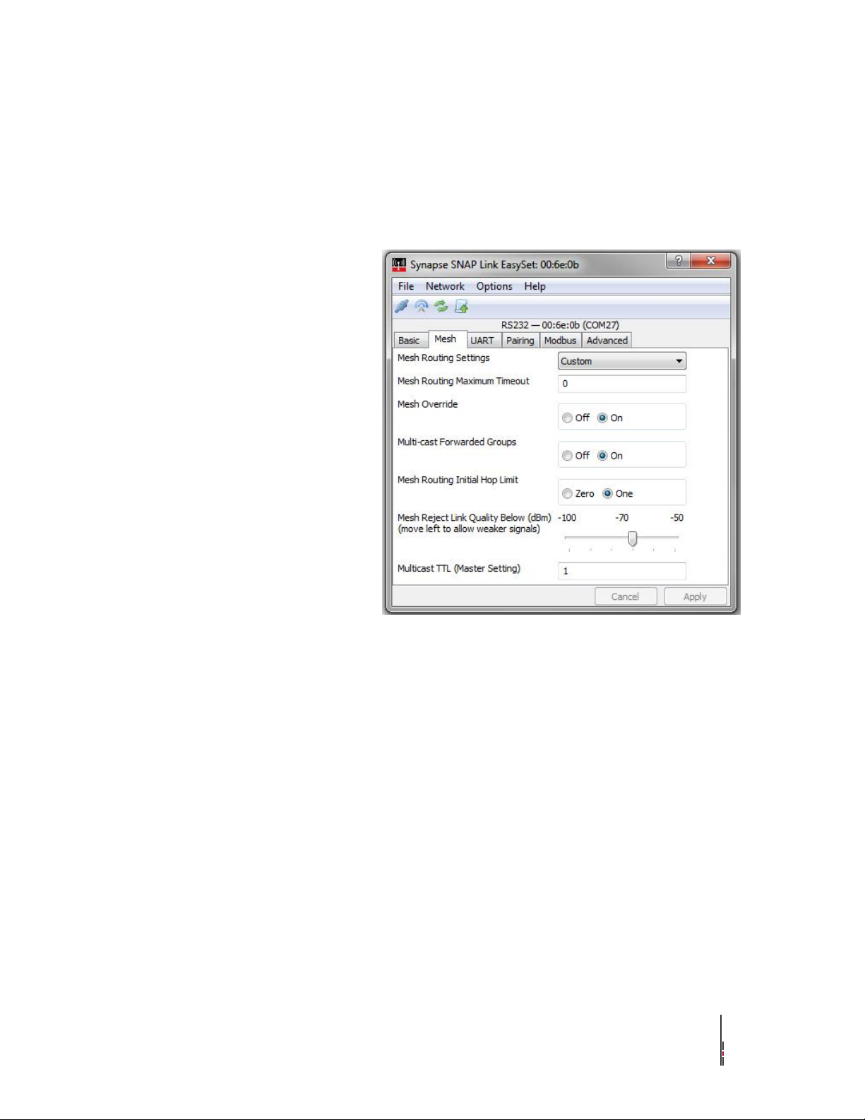
Note:
EasySet Versions earlier than V1.2.3 had three parameters shown
on the Basic tab: Mesh Routing Setting, Mesh Routing Maximum
Timeout and Mesh Override. These parameters are now located
on the Mesh Tab in EasySet versions 1.2.3 and higher.
Mesh Settings - Custom
Mesh Routing Setting
Synapse nodes on the same channel and same network communicate
with each other using mesh routing. This means any device can
communicate with any other device (they are all logical peers within
the mesh) even though in some cases units that are out of radio range
with each other might have to pass messages through intermediate
nodes.
Mesh routing can be enabled, disabled, or set to custom. Enable mesh
routing to allow a SNAP Link device to participate as a node in a
wider SNAP mesh network.
Mesh Routing Maximum
Timeout
If you set Mesh Routing to custom, then the maximum age, in
milliseconds, can be specified here. The default value should cover
most network topologies and should be changed only under the
direction of technical support. Be careful when changing these values
on remote nodes as you could make it impossible to communicate
with the node remotely.
Mesh Override
If you set Mesh Routing to custom, then check this box to indicate
mesh override. This means to use mesh routing, but not to route for
other nodes in the network.
SNAP Link EasySet Software SNAP Link User Guide 13
Page 20

Multi-Cast Forwarded Group
Select ―On‖ to have the connected SNAP Link adapter re-transmit or
re-broadcast any communications it receives from the Master. This is
typically enabled on a SNAP Link client mode adapter located
approximately halfway between the Master unit and the SNAP Link
adapter client that exhibits poor transmission signal strength behavior
as documented in the chapter called Troubleshooting.
Mesh Routing Initial Hop Limit
Select ―One‖ to have the connected SNAP Link adapter limit Hops to
―1‖. A hop limit of ―1‖ directs a SNAP Link unit to request routing
paths from other SNAP devices one hop away. It will automatically
attempt to discover a routing path up to five hops away, if this initial
one hop discovery fails. By setting this parameter to zero (―0‖), you
are telling the SNAP Link attached adapter to attempt sending a
packet directly to the address first, before seeing if there is a route
path to get to him. This setting is most useful when fast timing is
required and you are pretty sure they are within one hop distance.
Mesh Reject Link Quality From
(dBm)
The Mesh Reject Link Quality slider allows you to require the
minimum signal strength, as measured in dBm strength, that the
connected SNAP Link adapter is allowed to use for transmitting to a
neighboring node, even if the neighboring node is the Master device.
WARNING: setting this slider to the far right could result in an oddly
behaving mesh network, including no connection success at all. dBm
is a logarithmic setting from 0 to -127 and the slide allows you to
require the minimum signal strength to be between -100 (weak) to -50
(very strong). Sliding it to the left may allow more packets to become
lost, never arriving at its destination. Sliding it to the right will
decrease the number of these dropped packets, but may result in no
communication at all if set too far to the right.
Multicast TTL (Master Setting)
Multicast Time-To-Live parameter only needs to be set on the SNAP
Link adapter designated as the Master. As discussed in other sections,
Master transmissions use the Multicast protocol in order for multiple
clients to all receive the Master transmissions. By default, Multicast
TTL has been set to ―1‖, which means that even if a Client adapter’s
Mesh Routing Initial Hop Limit is set to ―On‖, they will not
retransmit or rebroadcast the Master’s transmissions. Example: There
are four SNAP Link adapters in a long linear line: Master, Client1,
Client2 and Client3. Master node transmissions do not get to the
farthest Client (3), but it appears Client1 could get it to Client2 and
Client2 could get it to Client3 since each Client is about 1/3 of the
distance away from its neighbors. In this example, setting the Master
TTL to 4 on the Master adapter and setting Client 1 and Client 2 to
―On‖ for the Mesh Routing Initial Hop Limit should make sure all
transmissions are received. Note: if you still have issues, please
review the Modbus Firmware appendix.
SNAP Link EasySet Software SNAP Link User Guide 14
Page 21
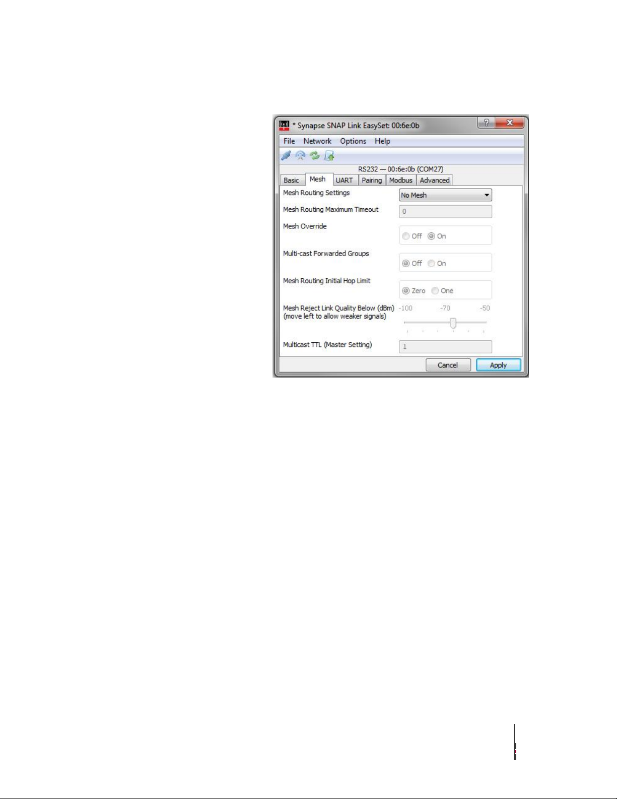
Mesh – No Mesh
Mesh Routing Settings – No
Mesh
Setting the Mesh Routing Settings parameter to ―No Mesh‖ keeps
transmissions to a minimum, reducing interference and collisions that
may add lag, or delays, in the smooth timing operation of your SNAP
Link adapters (sometimes referred to as a ―broadcast storm‖). Only
enable mesh routing if you have determined that you need some of
your Client mode adapters to help retransmit or rebroadcast
transmissions in order for all Clients to receive and transmit their
information.
SNAP Link EasySet Software SNAP Link User Guide 15
Page 22
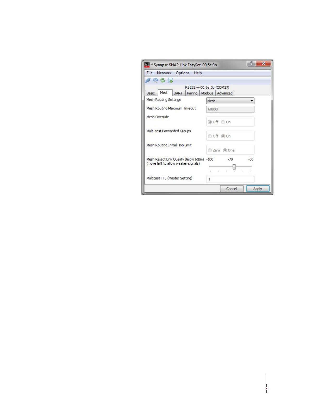
Mesh – Mesh Defaults
Mesh Routing Settings - Mesh
These are the default parameters when you select ―Mesh‖ from the
Mesh Routing Settings pull down menu. Selecting Mesh indicates that
you want the connected SNAP Link adapter to assume an additional
role of ―transmission repeater/router‖. As long as the Master adapter
has the Multicast TTL (Master Setting) assigned to a number larger
than 1, all nodes with this ―Mesh‖ pull down menu selection will
repeat unicast and multicast transmissions they receive.
SNAP Link EasySet Software SNAP Link User Guide 16
Page 23
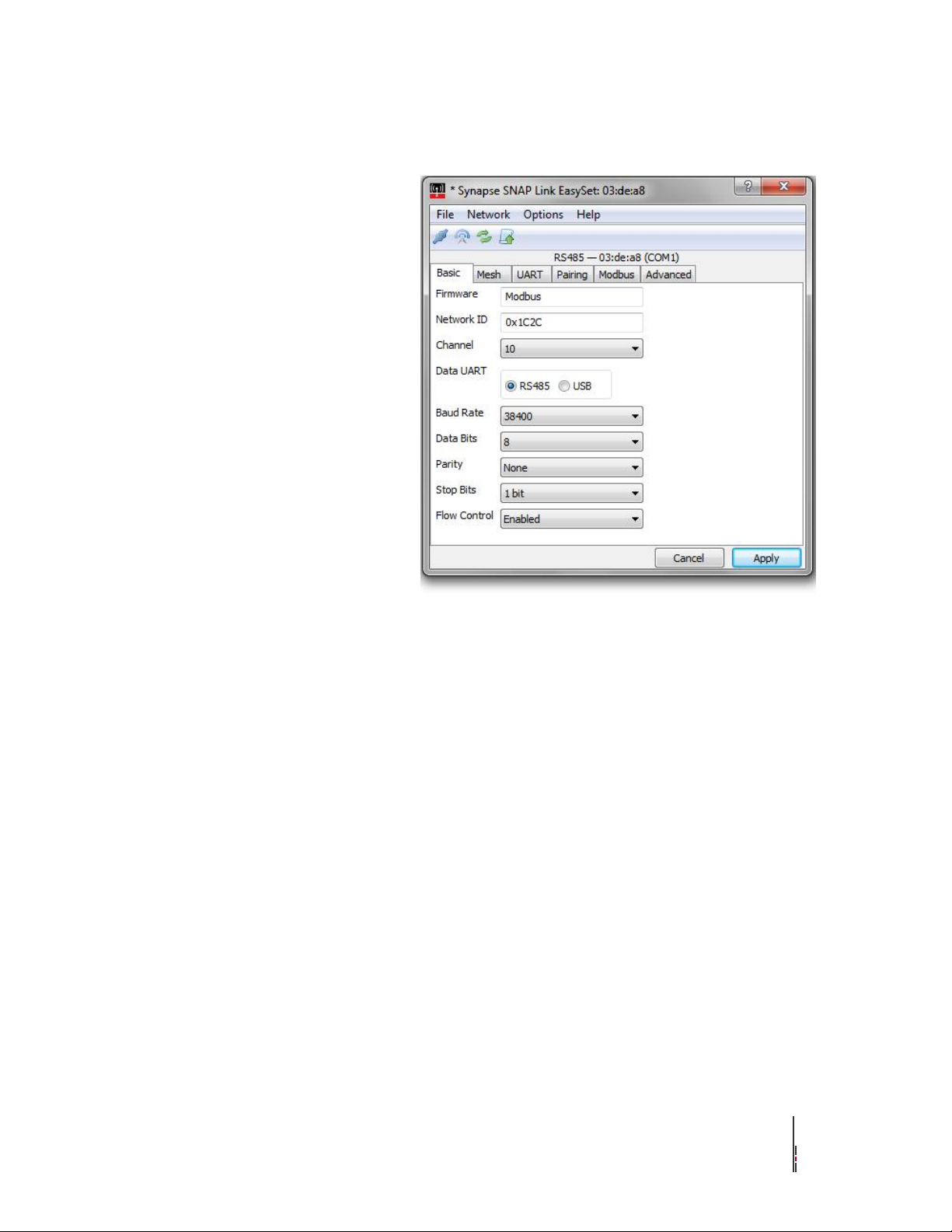
Modbus Firmware (If Script has
been loaded)
Modbus Firmware
A new tab called ―Modbus‖ has been added in the release of EasySet
V1.2.3 once a SNAP Link adapter has Uploaded the ―Modbus‖ script
and reset to factory default. The new Firmware field denotes this
connected SNAP Link adapter has had the script uploaded by
displaying ―Modbus‖ along with a new Modbus tab. The Modbus
script enables a new hardened wireless Modbus protocol that provides
the highest reliability transport along with the ability to fine-tune the
retransmissions and lag or latency introduced by those retries. Please
review the Modbus appendix later in this document for more
information.
SNAP Link EasySet Software SNAP Link User Guide 17
Page 24
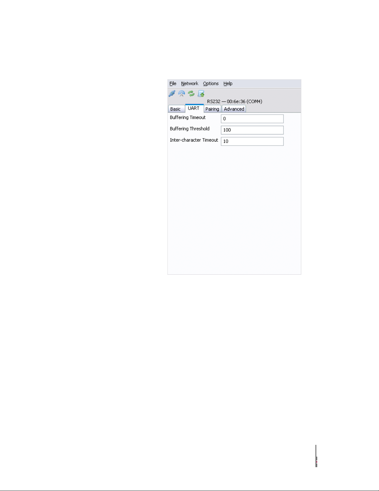
UART Settings
The UART tab contains three
parameters allowing you to fine
tune data transmission. These can
be set according to the needs of
the serial device. You may have
to adjust these, depending upon
transmission speed and the size
of data packets. See the chapter
on Application Usage Scenarios
for more help in setting these
parameters.
Buffering Timeout
This setting controls the overall serial data timeout. The value is in
milliseconds with the default being 0, or no timeout.
The Buffering Timeout controls the elapsed time between an initial
character being received and a packet of serial data being enqueued
for processing. When the timeout passes, regardless of the number of
characters buffered or the rate at which they are received, the buffered
data will be sent. The larger this value the more buffering that will
take place. However, while this allows for more data to be sent per
packet, which might be more efficient depending upon your
application, it also increases latency.
Note that other events, controlled by Buffering Threshold and Inter-
character Timeout, can also trigger the buffer of data to be sent.
SNAP Link EasySet Software SNAP Link User Guide 18
Page 25

Buffering Threshold
This setting indicates the maximum packet size used when sending
data. The default is 100 bytes and the maximum is 123 bytes. Values
over 100 are not recommended as they could result in buffer overrun.
Buffering Threshold causes buffered data to be sent whenever the
threshold is reached. However, triggering the Buffering Timeout or
Inter-character Timeout settings could cause data to be sent before the
threshold is reached.
Each packet of data includes a header, which comprises 12 bytes for
multipoint packets and 15 bytes for point-to-point packets. So, the
actual number of data bytes sent will be either 12 or 15 bytes fewer.
If you set Buffering Threshold to a large number, then larger, more
efficient packets will be sent, but with greater latency. At higher baud
rates setting this value too high can result in dropped characters.
Inter-character Timeout
This setting allows you to tune the inter-character serial data timeout.
This value is in milliseconds and defaults to 10.
Inter-character Timeout is the maximum elapsed time that should pass
before sending the enqueued packet after receiving a character. It
restarts with every received character. This parameter or Buffering
Timeout can trigger transmission of buffered data before Buffering
Threshold is reached. Conversely, if the timeouts are high or disabled
altogether, then data will be transmitted when the Buffering Threshold
is reached.
Setting a large Inter-character Timeout can give better multicast
transparent mode reliability but with greater latency.
SNAP Link EasySet Software SNAP Link User Guide 19
Page 26
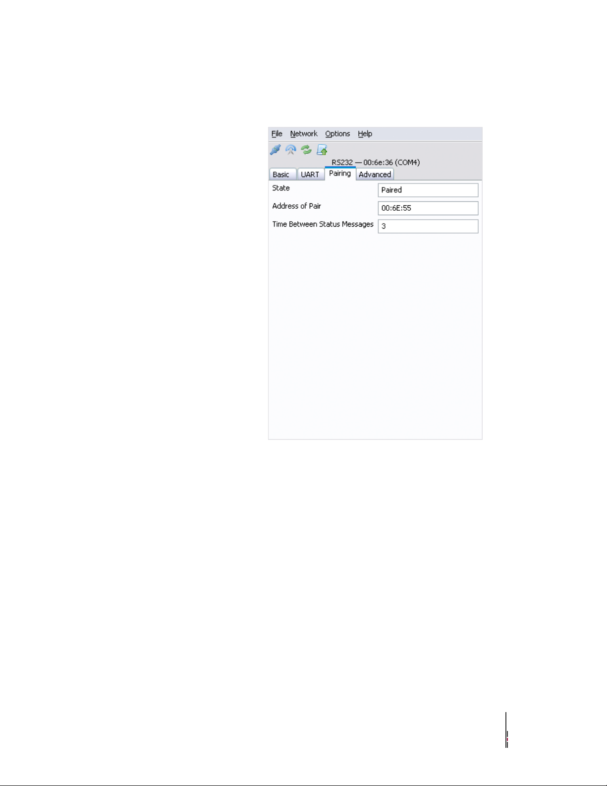
Pairing Settings
The Pairing tab indicates whether
the SNAP Link adapter is paired
with another adapter, which is
denoted by displaying the other
pair's SNAP address.
State
This is the paired state. The value can be:
‣ Simple Broadcast – Unit is in a reset state and is waiting to be
set up.
‣ Searching for Master – Unit is in multipoint mode and is
searching for a for a master unit with which to pair.
‣ Master – Unit is in multipoint mode and is the master. It is now
willing to accept slave units.
‣ Slave – Unit is in multipoint mode, is a slave, and has paired
with a master.
‣ Ready to Pair – Unit is in point-to-point mode and is looking
for another unit with which to pair.
‣ Paired – Unit is in point-to-point mode and has been paired with
another.
Address of Pair
When paired, this will be the device address the unit is paired with. If
a slave, this will be the address of the master. If a master, this field
will be blank.
Time Between Status Messages
The number of seconds between pings. The device will periodically
ping its partner to confirm connectivity.
SNAP Link EasySet Software SNAP Link User Guide 20
Page 27
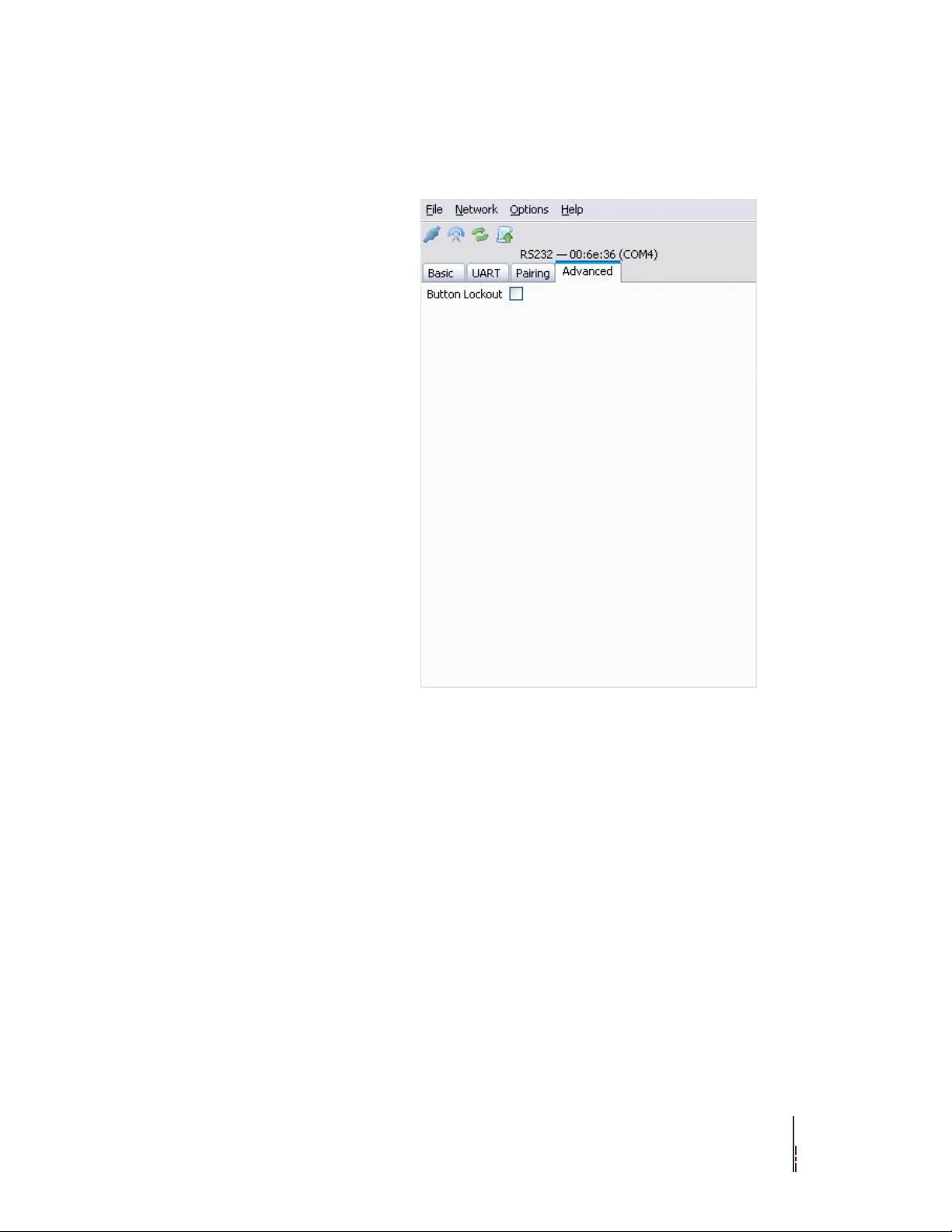
Advanced Settings
The Advanced tab contains a
single checkbox labelled Button
Lockout. When checked, the
MODE button on the front of the
SNAP Link adapter will be
disabled. However, the MODE
button can still be used to
perform a reset, putting the
SNAP Link device back into
broadcast state.
SNAP Link EasySet Software SNAP Link User Guide 21
Page 28
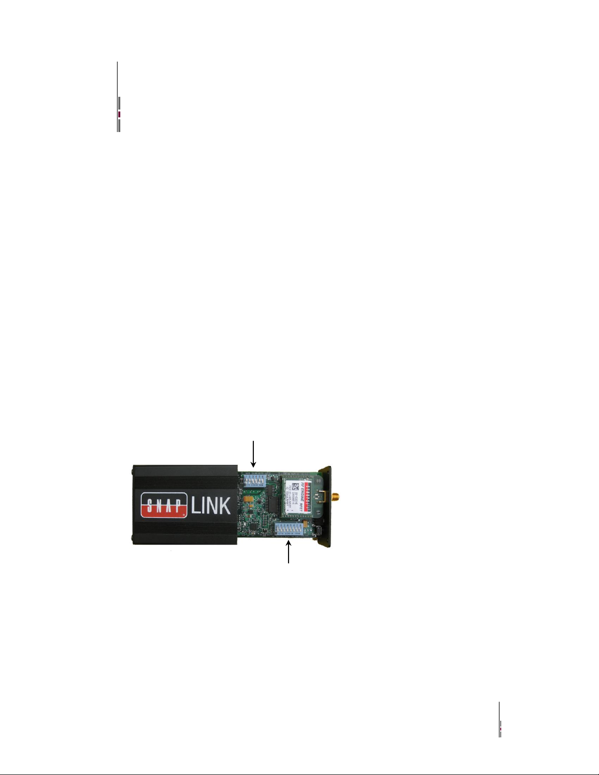
Configuring your Adaptor using the
DIP Switch 2 (SL485 only)
DIP Switch 1
DIP Switches
You use the MODE button on the front panel of your SNAP Link adapter to define which SNAP Link
adapters communicate with each other, as discussed in earlier sections of this manual. You use the EasySet
software to modify the entire range of parameters, also as discussed in earlier sections of this manual.
However, if you do not have access to a computer running EasySet, you can configure some communication
parameters using the DIP switches located inside the unit.
Changing DIP switch settings will override the default parameters, or parameters previously configured using
the EasySet software. However, EasySet can also override the DIP switch settings. SNAP Link adaptors have
built-in intelligence to determine if EasySet or the DIP switches were last used to change the configuration.
The general rule is: the last method used to change the settings is the one that takes precedence.
SL232 has a set of 8 internal switches that set Flow Control, Baud Rate, and SNAP Channel.
SL484 has the same set of 8 switches plus a second set of 6 switches that configure the device for either 2-
wire or 4-wire operation.
To access the DIP switches, remove the four screws on the antenna end of the device and slide out the
enclosed PC board to expose the switches.
Configuring your Adaptor using the DIP Switches SNAP Link User Guide 22
Page 29
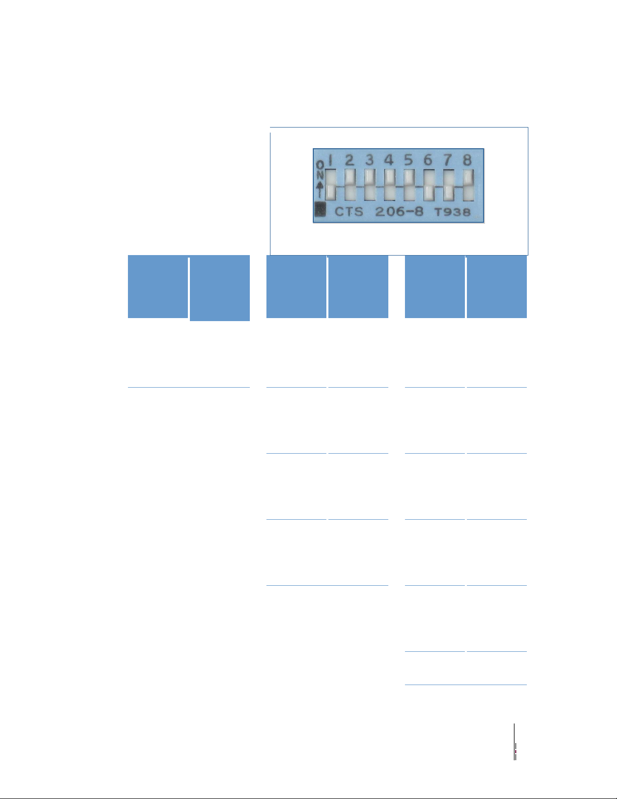
DIP Switch 1
DIP switch 1 consists of 8
individual switches, which are
applicable to all SNAP Link
devices. All possible switch
settings are shown in the
tables below. This example
indicates flow control off,
2400 BAUD, and SNAP
channel 9.
Switch
Setting1
Flow Control
Switch Setting
4 3 2
Baud Rate
Switch Setting
8 7 6 5
SNAP Channel
0 - off
Disabled
0 0 0
9600
0 0 0 0
0
1 - on
Enabled
0 0 1
19,200
0 0 0 1
1
0 1 0
38,400
0 0 1 0
2
0 1 1
57,600
0 0 1 1
3
1 0 0
115,200
0 1 0 0
4
1 0 1
300
0 1 0 1
5
1 1 0
1200
0 1 1 0
6
1 1 1
2400
0 1 1 1
7
1 0 0 0
8
1 0 0 1
9
1 0 1 0
10
Configuring your Adaptor using the DIP Switches SNAP Link User Guide 23
Page 30

1 0 1 1
11
1 1 0 0
12
1 1 0 1
13
1 1 1 0
14
1 1 1 1
15
Configuring your Adaptor using the DIP Switches SNAP Link User Guide 24
Page 31
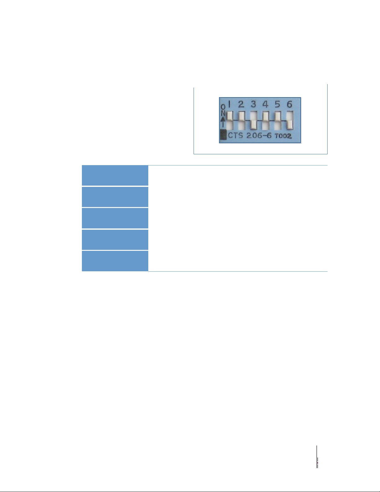
DIP Switch 2
DIP switch 2 consists of 6 individual
switches and is present only in SL485
devices. It is used to configure the device
for 2-wire or 4-wire operation. Note that 2-
wire is always half duplex and 4-wire can
be switched between half or full duplex.
RS-422 is always 4-wire, full duplex.
Switch
1 2 3 4 5
6
2-Wire Half Duplex
1 1 0 1 1
0
4-Wire Half Duplex
0 0 1 1 1
0
4 Wire Full Duplex
0 0 1 1 0
1
RS-422
0 0 0 1 0
1
Some device manufacturers might refer to these as 3-wire or 5-wire. This is referring to the same settings
described above, but are including the ground wire in their specification.
Configuring your Adaptor using the DIP Switches SNAP Link User Guide 25
Page 32

Application Usage Scenarios
The UART parameter settings in EasySet can affect end-to-end data communications performance between
the SNAP Link adapters and your RS-485/422/232 devices. This section provides several scenarios to
illustrate setting the UART parameters for optimal performance. Your application or device may require a
few trial-and-error adjustments before performing as desired. These scenarios provide recommended rule-ofthumb starting points to begin this trial-and-error process.
Refer to the UART discussion in the EasySet chapter for a description of the UART parameters, but in
summary, the three parameters are:
‣ Buffering Timeout – the total length of time to wait before buffered data is transmitted. The unit of
measure is milliseconds and the default is 0. 0 effectively turns the buffering timer off.
‣ Buffering Threshold – the minimum number of characters to enqueue before the buffer is transmitted.
SNAP Link contains a 123 byte buffer, but that must include a 12 byte header when in multipoint
mode and a 15 byte header when in point-to-point mode. The default value is 100. Values over 100
are not recommended, especially at high baud rates, because the buffer could be overrun resulting in
dropped characters.
‣ Inter-character Timeout – the length of time to wait between the arrival of characters before the buffer
is transmitted. The unit of measure is in milliseconds and the default is 10.
Scenario 1: Card Scanner
In this example, a card scanner is sending small but continuous packets of data. One of its requirements is
fast turnaround, hence a small buffer needs to be emptied frequently to reduce latency. Suggested parameters
are:
‣ Buffering Timeout – 0 turns this timer off. In this case, we’ll let the threshold and inter-character
timer take care of flushing the buffer.
‣ Buffering Threshold – This should be set to the size of the card scanner packets plus an additional 12
or 15 bytes of header. So if the packet size of the payload is 16 bytes, then this buffer could be set to
28 if using multicast or 31 bytes if using unicast. SNAP Link adapters configured as masters in a
multipoint configuration always use multicast. Slaves and paired adapters always use unicast
communications.
‣ Inter-character Timeout – This should be a low number, such as 3 to 10 milliseconds, to prevent data
from being buffered too long. Higher baud rates should use a lower value, and lower baud rates need a
higher value.
Application Usage Scenarios SNAP Link User Guide 26
Page 33

Scenario 2: File Transfer, Continuous Stream
In this example a large continuous block of data is transmitted, such as what would take place during a file
transfer. In this case latency is not an issue, but maximizing the transfer rate is. Suggested parameters are:
‣ Buffering Timeout – This should be set to a fairly large number to ensure the transmit buffer is filled
before being transmitted. At 19,200 baud, an appropriate number would be 50 to 60 milliseconds.
‣ Buffering Threshold – This should be set to as large a number as possible. The maximum would be
108 bytes in point-to-point mode and 111 bytes in multipoint mode, however as stated above,
numbers above 100 are not recommended.
‣ Inter-character Timeout – This should be set to 0 to turn this parameter off. We don’t want the buffer
transmitted if the serial device should hesitate for a few milliseconds. Instead, we want the buffer to
be filled to capacity, so we’ll let the other two parameters control when the buffer is transmitted.
Scenario 3: Lowest Latency at Highest Baud Rate
In this example we have bursts of up to 75 bytes that we want transmitted with the least amount of latency.
Suggested parameters are:
‣ Buffering Timeout – This should be set to a small number to keep the smaller packets flowing and
allow the buffer to fill when a larger packet arrives. At 19,200 baud around 35 milliseconds should
work, and at 115,200 baud around 5 milliseconds should suffice.
‣ Buffering Threshold – Set this value to 90 to allow the larger packets to buffer (75 bytes plus 15 bytes
for the unicast header). The Buffering Timeout will force the smaller packets to be sent, preventing
them from sitting in the transmit buffer for too long.
‣ Inter-character Timeout – This parameter should be smaller than the Buffering Timeout to force
transmission of very small payloads with pauses between them. In this scenario, set this parameter at
about half of the Buffering Timeout setting.
Application Usage Scenarios SNAP Link User Guide 27
Page 34

Troubleshooting
In the realm of wireless communications, many factors can affect reliable data communications. This section
lists a number of known factors and possible remedies.
If your question is not adequately answered here, visit the SNAP Link support forum on the Synapse
Wireless website where you can post a question and interact with other SNAP Link users. The SNAP Link
Support forum can be accessed at:
forums.synapse-wireless.com/forumdisplay.php?f=11
Signal Strength Problems
SNAP Link adapters should communicate well when placed in near proximity of one another (as indicated by
a mostly green LED A), why might they not communicate well when moved father apart (as indicated by
LED A turning amber, indicating weak signal strength, or red, indicating loss of signal)? You can make
several adjustments to remedy this situation:
‣ Try orienting the external antenna into different positions. Since antennas work best when they are in
the same spacial plane, essentially parallel to one another without being directly above or below each
other, try to position the antennas of all your SNAP Link devices in the same orientation.
‣ There could be other interference problems in your vicinity such as large metal objects, dense foliage,
and other objects that prevent signal transmission or attenuation (signal loss). Microwave ovens can
cause interference problems. Try moving the units physically to another usable location to see if
signal strength improves.
‣ Try changing the channel of each device. There are 16 separate channels (0 – 15) spread within the
2.4GHz frequency. Various other 2.4GHz devices, such as cordless phones and WiFi routers, may be
flooding one channel, but not another one.
‣ Refer to the Advanced Management section for reference to the Synapse Portal® software. This
software contains a Channel Analyzer tool that can help you determine which channel has the least
traffic interference.
Multiple Masters
In a multipoint network, if SNAP Link devices are unable to pair with a master, check for the presence of
multiple masters.
There can be only one master in a multipoint network. If you wish to operate multiple masters within the
same vicinity, then be sure to set each master to a different channel and/or network ID using either EasySet or
the DIP switches. To reduce crosstalk, set the network channels as far apart as possible.
When operating normally, a SNAP Link master will slowly blink the A LED, alternating between green and
amber. If it detects the presence of another master on the same channel, it will then alternate the colors
between red and amber.
Troubleshooting SNAP Link User Guide 28
Page 35

Can’t Find a Master
If a SNAP Link device is unable to pair with a master, there may be several possible problems:
‣ Ensure there are not multiple masters on the network by observing LED A as described above.
‣ Ensure all units on the multipoint network are using the same channel number and network ID.
‣ Ensure the unit is within broadcast range of the master. If in doubt, try to pair the units within the
same room. Once paired, move the slave unit farther away while observing LED A. It should start off
green, but if the unit is moved to the fringe of its broadcast range, the LED will turn amber, indicating
weak signal strength. If the LED turns red, then it has lost its connection with the master.
‣ Try adjusting the antennas as described above.
Poor Performance
If you believe your SNAP Link adapter are not performing adequately, this could be caused by a number of
factors, such as:
‣ Poor signal strength – try adjusting the antennas as described above.
‣ Incorrect data communications parameters – confirm your serial communication settings in EasySet
with those of your serial device.
‣ Premature sending of packets, holding on to packets for too long, or just dropped packets – try
optimizing the UART parameters for your particular application. Revisit the UART parameter
settings in the EasySet chapter and also review the Application Usage Scenarios chapter.
Paired but not Communicating
If a unit appears to be paired in multipoint mode, but still doesn’t work, check the communications
parameters using EasySet. If you don’t see an occasion blink of the green A LED, then you might have an
incorrect setting in baud rate, flow control, stop bits, parity, or flow control. If you have more than two SNAP
Link units, confirm that each unit is paired to the desired unit. Each unit's address is printed on a label located
on the bottom. The unit it is paired with can be confirmed using EasySet.
Troubleshooting SNAP Link User Guide 29
Page 36

Frequently Asked Questions
Does the SL485 product provide power to an attached device off the terminal block? In other words, if my
RS-485 device requires power, can it obtain that power from the SNAP Link product?
★ No. The SNAP Link family requires only a tiny fraction of the power specified by the RS-485 standard
and does not have the capability of driving an RS-485 device from the SNAP Link provided power
source.
If I power off and power back on a SNAP Link product, does it forget the configuration changes I have
previously applied, such as baud rate, parity, flow control, UART parameters, channel, or network ID?
★ No. SNAP Link units store those parameters into non-volatile (NV) RAM, maintaining your settings
when power is cycled.
As shipped from the factory, are the SL485 products configured to use 2-wire or 4-wire RS-485 cabling?
★ Factory default settings are to assume an RS-485 2-wire cable. To support a 4-wire configuration, the
unit must be opened and some settings on the six DIP switch box must be changed as shown in the
chapter on DIP switch settings.
I have a 3-wire or 5-wire RS-485. Do you support those as well?
★ Yes. Some documentation does not count the ground wire when discussing an RS-485 cable.
Therefore, a 2-wire isn’t counting the ground wire, while saying 3-wire does count it. They are both
the same. A 4-wire is also the same as saying 5-wire for the same reason.
In a multipoint configuration my master device shows an amber flicker periodically. Does this mean it has a
weak signal strength? Can I determine the signal strength on the master unit?
★ No. A master’s A LED displays a mostly green color, with a regular amber flash. This display simply
indicates that the unit is the master node in a multipoint network.
★ The master does not indicate signal strength when communicating with its slaves. However, by
looking at LED C you can determine when the master unit has data transmission activity with its
attached serial device.
★ The only way to determine signal strength in a multipoint network is by looking at LED A on the slave
units to see if they have a good connection with the master.
Frequently Asked Questions SNAP Link User Guide 30
Page 37

I need to replace the master SNAP Link unit in a multipoint setup that has been working. Must I reset each
device, or can I merely set up the new master?
★ You will need to perform a simple one-button process at each slave. This is by design since you
wouldn’t want slave devices to automatically switch to a new master if one were one to be powered up
for a different purpose. This is documented in the setup chapter, but the process is as follows:
1. Hold down the MODE button for 5 seconds until LED A begins to flash red. Release the MODE
button, LED A will no longer be lit.
2. Click the MODE button four times in rapid succession. LED A will rapidly flash amber to indicate
it is seeking a master and, upon finding one, will change to green.
Is the SNAP Link RS-232 product a DTE (data terminal equipment) or a DCE (data communications
equipment)? When do I need to use a null modem cable or adapter?
★ The SNAP Link RS-232 devices use a standard DB9 female connector configured as a DCE. It can be
connected to a DTE using a straight through cable. If you need to connect an SL232 to another DCE
device, then a null modem adapter, or cross over cable, will be required. See the discussion of RS-232
pin outs for further information.
Frequently Asked Questions SNAP Link User Guide 31
Page 38
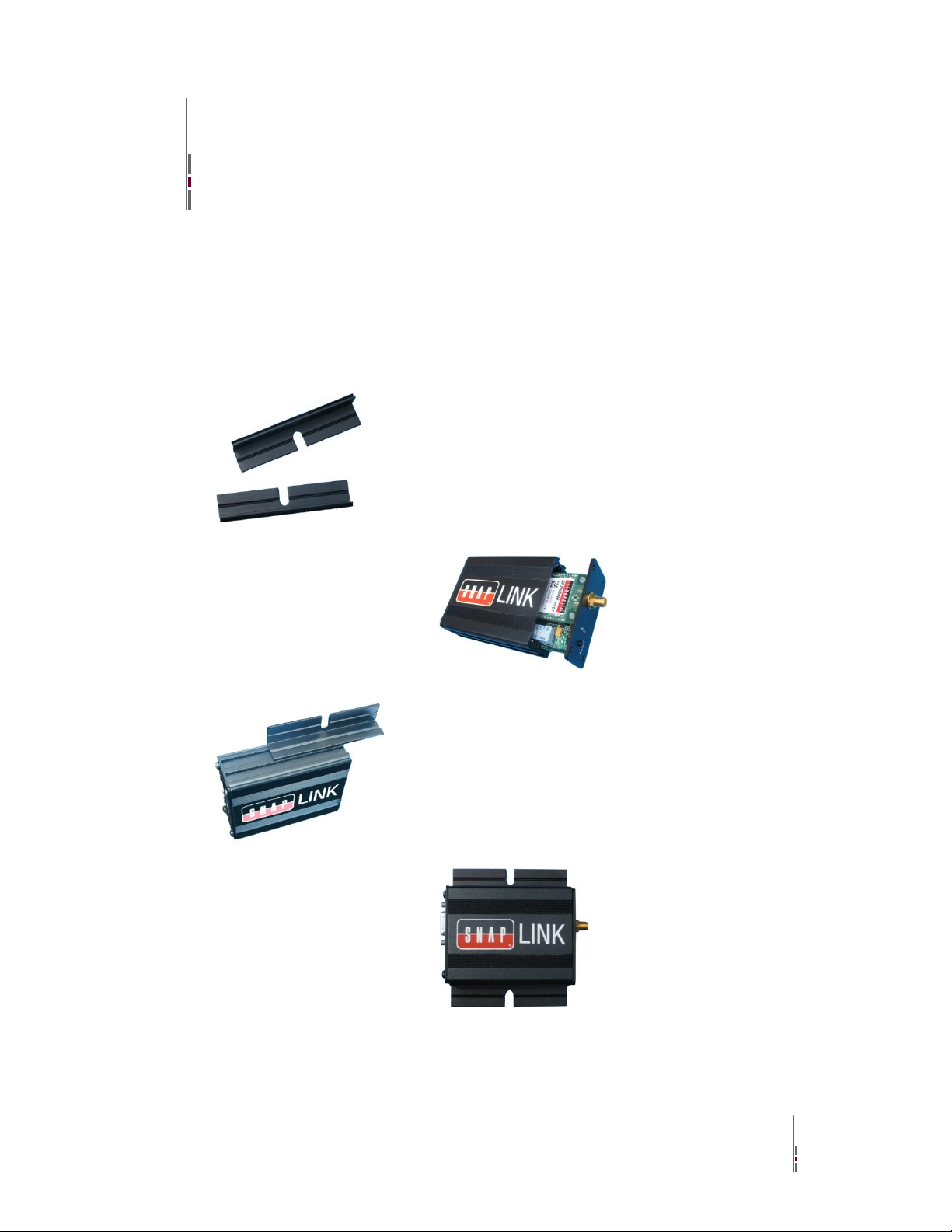
Appendices
There are two mounting brackets,
one for each side of the SNAP Link
box.
Remove an end panel by unscrewing
the 4 screws and removing the panel.
Slide the brackets into place as
shown. Reattach the end panel using
the 4 screws. The end panels will
securely hold the brackets in place.
The completed assembly is now
ready to be hung on a ceiling or
wall.
Mounting Options
SNAP Link devices can sit on a table top or be wall mounted using the included mounting brackets. To install
the brackets, one of the end panels must be removed and the brackets slid into place.
Appendices SNAP Link User Guide 32
Page 39
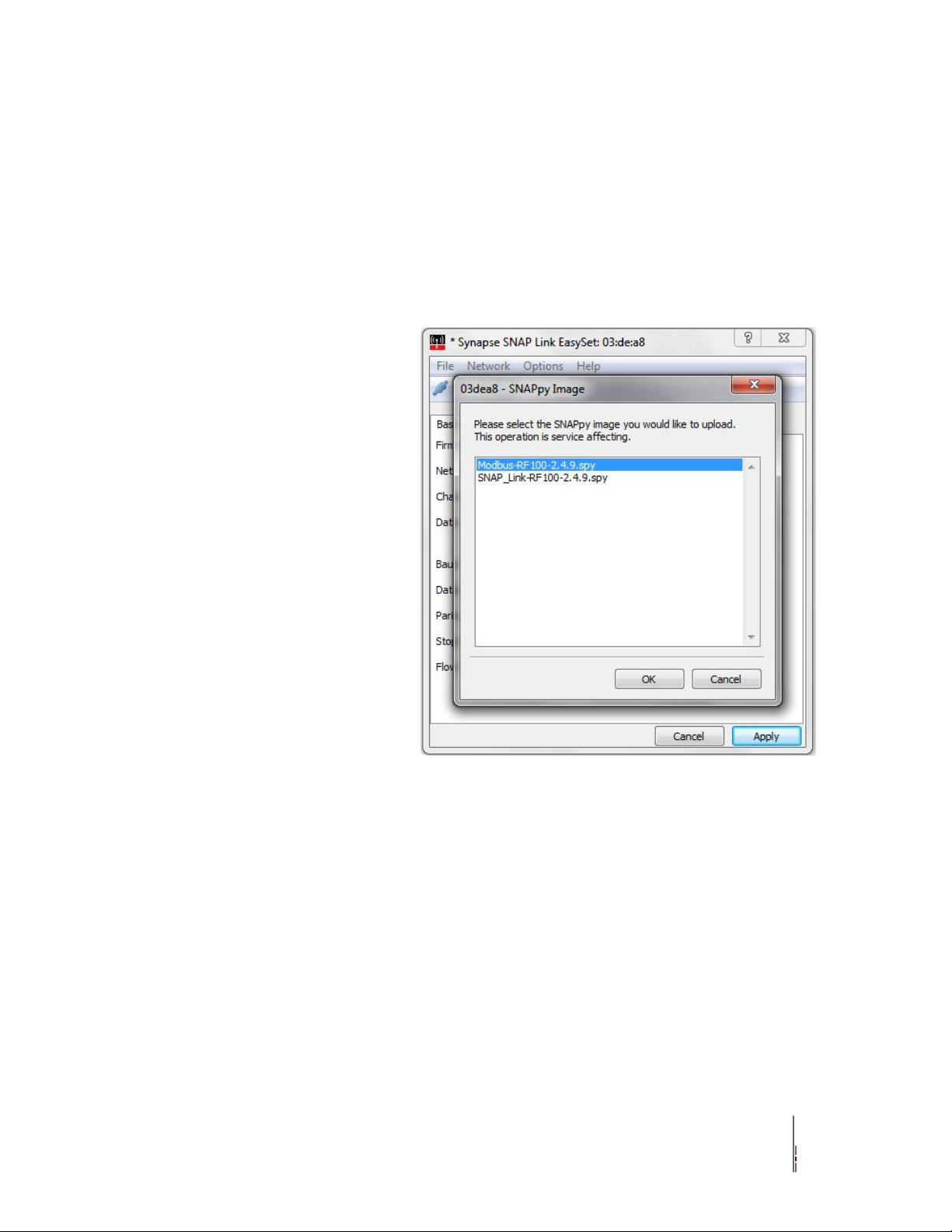
Modbus Firmware
Select Modbus script, as shown,
for uploading the Modbus
firmware to the connected SNAP
Link adapter
With the release of EasySet V1.2.3, SNAP Link adapters can load a new version of script firmware to
increase the reliability of wireless transmissions, by allowing an automatic number of retransmissions by the
Master adapter. This multicast retry feature ensures the master continues to retransmit a command if no
response is received due to the original transmission. By adjusting two parameters, you can balance the
number of retries attempted by the Master adapter. However, lag or latency is introduced by each retry.
Appendices SNAP Link User Guide 33
Page 40
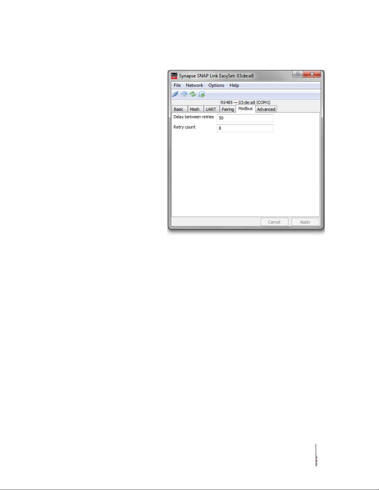
The Modbus tab enables
retransmission by the Master
adapter based on retry count and
the waiting period between them.
Delay between retries.
The delay between retries is a millisecond timer that counts down
after the Master adapter transmits a modbus command. Once the
transmission occurs, the Master adapter will count down the assign
number, in milliseconds. If a reply is not received before the timer
reaches zero, the Master unit will retransmit the original Modbus
command up to the number of Retry count assigned
Retry count
The number of times the Master will re-transmit the original broadcast
if no response is received within the Delay between retries setting.
Note: Your Modbus application may be affected by lag due to
these settings. If a Master adapter has to retry to the maximum
number set, it will incurr a lag in milliseconds equal to the
following formula: “Delay between retries” * “Retry Count” =
“Maximum milliseconds of lag potentially added after each
Modbus command is transmitted.
Appendices SNAP Link User Guide 34
Page 41
Advanced Management
SL232K and SL485K
SL232M and SL485M
Radio Frequency
2.4 GHz (2.4000 – 2.4835 GHz)
2.4 GHz (2.4000 – 2.4835 GHz)
Spreading Spectrum Type
Direct Sequence (DSSS)
Direct Sequence (DSSS)
Frequency Control
Offset-Quadrature Phase Shift
Keying (O-QPSK)
Offset-Quadrature Phase Shift
Keying (O-QPSK)
Network Topology
Point-to-Point Paired; PointMultipoint (Master/Slave);
Transparent Mesh Networking
Point-to-Point Paired; PointMultipoint (Master/Slave);
Transparent Mesh Networking
Channel Capacity
16 isolated channels; 65534
logical networks per channel
16 isolated channels; 65534
logical networks per channel
Serial Data Interface
Two: Selectable between RS232/422/485 or USB
Two: Selectable between RS232/422/485 or USB
Raw Data Rate
250 Kbps
Software selectable: 250 Kbps –
2 Mbps
Supported Baud Rate
300, 1200, 2400, 4800, 9600,
19,200, 38,400, 57,600, 11,5200
300, 1200, 2400, 4800, 9600,
19,200, 38,400, 57,600, 115,200
Max Sustainable Throughput
19,200 bps
115,200 bps
SL232K and SL485K
SL232M and SL485M
The SNAP Link EasySet software was designed to set up SNAP Link adapters quickly and easily. However,
if you should encounter situations where a more powerful tool is needed, Synapse Wireless offers Portal™,
an advanced SNAP network Administration tool, as a free download from the web site. To access the
download you will need to register on the Synapse forum site at:
forums.synapse-wireless.com/register.php
Once registered, download Portal and its related documentation from:
forums.synapse-wireless.com/showthread.php?t=9
Specifications
General
Power Requirements
Appendices SNAP Link User Guide 35
Page 42
SL232K and SL485K
SL232M and SL485M
Supply Voltage
4 – 5.25 VDC; Standard micro-
B USB Universal Connector
4 - 5.25 VDC; Standard micro-B
USB Universal Connector
Max. Power Consumption
RS-232: 0.6WRS-485: 0.825W
RS-232: 0.51WRS-485: 0.735W
Physical Properties
SL232K and SL485K
SL232M and SL485M
Enclosure Type
Extruded aluminum, black
anodized, wall mount brackets
included
Extruded aluminum, black
anodized, wall mount brackets
included
Enclosure Size
1.18H x 2.5W x 3.15L in.(3 x
6.4 x 8 cm)
1.18H x 2.5W x 3.15L in.(3 x
6.4 x 8 cm)
Weight
RS-232: 6.12 oz (174 g)RS-485:
6.25 oz (177 g)
RS-232: 6.12 oz (174 g)RS-485:
6.25 oz (177 g)
Operating Temperature
-30º to +85ºCIncluded wall
plug: 0 to +45ºC
-30º to +85ºCIncluded wall
plug: 0 to +45ºC
Operating Humidity
10 to 90% non-condensing
10 to 90% non-condensing
Wireless Link Failure
Integrated Wireless Link Failure
LED indicator
Integrated Wireless Link Failure
LED indicator
SL232K and SL485K
SL232M and SL485M
Protocol
IEEE 802.15.4, SNAP
IEEE 802.15.4, SNAP
Indoor Range (with included
antenna)
Up to 1000 feet indoors Line of
Sight (LoS). RF interference can
reduce range.
Up to 500 feet indoors at 250
Kbps wireless rate (125 feet at 2
Mbps wireless rate)
Outdoor Range (with included
antenna)
Up to 3 miles Line of Sight (LoS)
Up to 6 miles at 250 Kbps
wireless rate LoS (1.5 miles at 2
Mbps wireless rate LoS)
RF Transmit Power
63 mW (18 dBm)
63 mW (18 dBm)
Receive amplifier Gain
10 dBm
10 dBm
RF (Wireless) Properties
Appendices SNAP Link User Guide 36
Page 43
SL232K and SL485K
SL232M and SL485M
Receiver Sensitivity
-102 dBm at 1% packet error rate
-102 dBm at 1% packet error rate
Features
Real-time RSSI signal strength
indicator; AT Command;
Terminal Emulation; Modem
emulation
Real-time RSSI signal strength
indicator; AT Command;
Terminal Emulation; Modem
emulation
Antenna
SL232K and SL485K
SL232M and SL485M
Type Included
External Reverse Polarity SMA
connector, omni directional
External Reverse Polarity SMA
connector, omni directional
Gain
3.2 dBi
3.2 dBi
Length
5.875 in (14.9 cm)
5.875 in (14.9 cm)
Impedance
50 Ohms unbalanced
50 Ohms unbalanced
SL232K and SL485K
SL232M and SL485M
FCC Part 15, Class B
Yes
Yes
Power Supply
UL
UL
RoHS (lead free) Compliant
Yes
Yes
Energy Star Compliant
Yes
Yes
IC Certification
Yes
Yes
SL232K
SL232M
Connector
DB9F DCE
DB9F DCE
Data bit; Parity; Stop bit
7, 8; no parity, even, odd; 1
7,8; no parity, even, odd; 1, 2
Certifications
RS-232
Appendices SNAP Link User Guide 37
Page 44

RS-485/422
SL485K
SL485M
Connector
Terminal block; 2 or 4 wire:
TX+, TX-, RX+, RX-, GND
(selectable)
Terminal block; 2 or 4 wire:
TX+, TX-, RX+, RX-, GND
(selectable)
Data bit; Parity; Stop bit
7, 8; no parity, even, odd; 1
7, 8; no parity, even, odd; 1, 2
SL232K and SL485K
SL232M and SL485M
OS Support
Microsoft Windows XP (SP2) or
Windows 7
Microsoft Windows XP (SP2) or
Windows 7
Configuration
EasySet - Configuration Tool
Included
EasySet – Configuration Tool
Included
Software
Regulatory Information and Certifications
RF exposure statement
This equipment complies with FCC radiation exposure limits set forth for an uncontrolled environment. This
equipment should be installed and operated with minimum distance of 20cm between the radiator and your
body. This transmitter must not be co-located or operating in conjunction with any other antenna or
transmitter.
FCC certifications and regulatory information (USA only)
FCC PART 15 CLASS B
These devices comply with part 15 of the FCC rules. Operation is subject to the following two conditions:
(1) These devices may not cause harmful interference, and (2) These devices must accept any interference
received, including interference that may cause harmful operation.
RADIO FREQUENCY INTERFERENCE (RFI) (FCC 15.105)
This equipment has been tested and found to comply with the limits for a Class B digital device, pursuant to
Part 15 of the FCC Rules. These limits are designed to provide reasonable protection against harmful
interference in a residential installation. This equipment generates, uses, and can radiate radio frequency
energy and, if not installed and used in accordance with the instructions, may cause harmful interference to
radio communications. However, there is no guarantee that interference will not occur in a particular
installation.
If this equipment does cause harmful interference to radio or television reception, which can be determined
by turning the equipment off and on, the user is encouraged to try to correct the interference by one or more
of the following measures:
‣ Reorient or relocate the receiving antenna.
Appendices SNAP Link User Guide 38
Page 45

‣ Increase the separation between the equipment and receiver.
‣ Connect the equipment into an outlet on a circuit different from that to which the receiver is
connected.
‣ Consult the dealer or an experienced radio/TV technician for help.
LABELING REQUIREMENTS (FCC 15.19)
This device complies with Part 15 of FCC rules. Operation is subject to the following two conditions: (1)
this device may not cause harmful interference, and (2) this device must accept any interference received,
including interference that may cause undesired operation.
If the FCC ID for the module inside this product enclosure is not visible when installed inside another device,
then the outside of the device into which this product is installed must also display a label referring to the
enclosed module FCC ID.
Modifications (FCC 15.21)
Changes or modifications to this equipment not expressly approved by Synapse Wireless, Inc. may void the
user’s authority to operate this equipment.
Declaration of Conformity
(In accordance with FCC 96-208 and 95-19)
Manufacturer’s Name: Synapse Wireless, Inc.
Headquarters: 500 Discovery Drive
Huntsville, Al 35806
Appendices SNAP Link User Guide 39
Page 46

Synapse Wireless, Inc. declares that the products:
Product Name Model Number
SNAP Link RS232 SL232K-001
SNAP Link RS485/422 SL485K-001
To which this declaration relates, meet the requirements specified by the Federal Communications
Commission as detailed in the following specifications:
‣ Part 15, Subpart B, for Class B equipment
‣ FCC 96-208 as it applies to Class B personal computers and peripherals
The products listed above have been tested at an External Test Laboratory certified per FCC rules and has
been found to meet the FCC, Part 15, Emission Limits. Documentation is on file and available from
Synapse Wireless, Inc.
Industry Canada (IC) certifications
This digital apparatus does not exceed the Class B limits for radio noise emissions from digital apparatus set
out in the Radio Interference Regulations of the Canadian Department of Communications.
Le present appareil numerique n’emet pas de bruits radioelectriques depassant les limites applicables aux
appareils numeriques de la class B prescrites dans le Règlement sur le brouillage radioelectrique edicte par le
ministère des Communications du Canada.
Appendices SNAP Link User Guide 40
 Loading...