


User’s Manual

Contents
3.8.3 Distortion . . . . . . . . . . . . 19
3.8.4 Phaser . . . . . . . . . . . . . . 20
3.8.5 Chorus/Flanger . . . . . . . . . 21
3.8.6 Delay . . . . . . . . . . . . . . 22
3.8.7 Reverb . . . . . . . . . . . . . . 23
3.8.8 Compressor . . . . . . . . . . . 24
1 Introduction and Overview 3
2 Basic Operation 4
2.1 Patch Controls . . . . . . . . . . . . . 4
2.2 Polyphony . . . . . . . . . . . . . . . . 4
2.3 Pitch Wheel . . . . . . . . . . . . . . . 4
2.4 Modulation Wheel . . . . . . . . . . . 4
2.5 Aftertouch . . . . . . . . . . . . . . . . 5
2.6 Using Antidote as an effect device . . . 5
3 Sound Parameters 6
3.1 Patch Structure . . . . . . . . . . . . . 6
3.2 Oscillators . . . . . . . . . . . . . . . . 7
3.2.1 Oscillator 1+2 . . . . . . . . . . 7
3.2.2 Sub Oscillators and Mixer . . . 10
3.3 Filter . . . . . . . . . . . . . . . . . . . 10
3.4 Modulation Envelope . . . . . . . . . . 13
3.5 Filter Envelope . . . . . . . . . . . . . 14
3.6 Amplitude Envelope . . . . . . . . . . 15
3.7 LFOs . . . . . . . . . . . . . . . . . . . 15
3.8 Effects . . . . . . . . . . . . . . . . . . 17
3.8.1 EQ . . . . . . . . . . . . . . . . 17
3.8.2 Bass . . . . . . . . . . . . . . . 19
4 Modulation Matrix 25
4.1 List of Sources . . . . . . . . . . . . . . 25
4.2 List of Destinations . . . . . . . . . . . 27
5 Arpeggiator 33
6 Back Panel 35
7 MIDI Reference 37
Credits 40
2 Antidote User’s Manual

1 Introduction and
Overview
Thank you for choosing Synapse Audio Antidote!
Antidote RE is a virtual-analog synthesizer for Propellerhead Reason. Antidote combines high audio
quality, flexibility and a fast work flow in an easyto-use plugin. It was specifically developed to complement Reason, and to yield the best possible sound,
integration and user experience.
Antidote RE comes feature packed with two stereo
oscillator banks, each emitting a stack of up to 24 high
quality virtual-analog oscillator waveforms.
The oscillators pass through the filter stage, which
employs the latest zero-delay feedback designs. This
recent technology is quickly gaining a lot of popularity, as it is able to mimic the behavior of analog filters
much better than previous designs.
Envelopes and LFOs further shape the sound, and
the modulation matrix — which can modulate almost
any sound parameter — adds the necessary depth to
realize complex sounds. The output of the synthesis
stage finally passes through a massive effect chain comprising EQ, Distortion, Phaser, Chorus, Delay, Reverb
and a Compressor effect. All effects can be enabled
and used simultaneously.
The back panel allows to connect Antidote RE to
other devices, to add extra modulation via CV Inputs,
to feed the effect chain with the outputs from other
instruments and to connect Reason’s step sequencers.
In contrast to conventional plugin standards, there
is little difference between using Antidote RE as an
instrument and as an effect. Both is possible and intended, and the vast modulation options apply equally
well in both cases.
3 Antidote User’s Manual

2 Basic Operation
2.1 Patch Controls
The patch operation in Antidote RE is the same as
in any other Reason device. To select a patch, either
click on the patch name, the folder icon or the arrow
buttons. To save a patch, click on the disk icon.
2.2 Polyphony
Each key that you press triggers a voice, with a pitch
determined by the key number. As each voice requires
CPU time, the total number of available voices is limited. The maximum number of available voices can be
adjusted by changing the POLY parameter in the top
left. Note that two special modes exist, Mono and
Mono-Legato. In both modes, only a single voice is
audible at a time. When multiple keys are pressed in
succession and sustained, the one hit last is audible.
Release it to snap back to the previous key (make sure
this one is still pressed!). This permits a unique style
of playing, which is particularly useful in combination
with the Glide knob. You can smoothly glide from
one note to another in this way. The difference between Mono and Mono-Legato is that the Mono mode
retriggers all envelopes whenever you press a key, while
the Legato mode will not change the envelope states
during a slide from one note to another.
2.3 Pitch Wheel
The pitch bend wheel changes the pitch of the current
sound. The minimum and maximum settings can be
changed on the backside of the device, in semitones.
There is two separate controls, one for up and one for
downwards motion. By default, the pitch bend ranges
from -2 (down) to +2 (up) semitones.
2.4 Modulation Wheel
The modulation wheel changes one or more sound parameters in real time, and adds expressiveness to your
performance. The parameter to change can be specified in the modulation matrix, by selecting Mod Wheel
in the source column, then choosing an arbitrary sound
parameter to modify from the destination list. Move
the corresponding AMT knob to the right, to specify
how strong the modulation should be at most.
A common application of the modulation wheel is
to open the filter with it, or to add vibrato/tremolo
4 Antidote User’s Manual

type effects. To do this, use LFO1*MW or LFO2*MW
in the modulation matrix source column, which multiplies the current LFO state with the modulation wheel
value (see chapter 4 for a more detailed description of
the modulation matrix).
2.5 Aftertouch
Aftertouch is another common way to add expressiveness to a sound. Aftertouch measures the pressure applied to all keyboard keys as a whole. When holding
down a chord, for instance, then increasing pressure,
you can add a vibrato effect to the sound. The aftertouch programming is identical to how you program
the modulation wheel. Using the previous example,
choose LFO1*AT or LFO2*AT as a source, then any
arbitrary sound parameter from the destination list,
to get a vibrato type effect.
Note that aftertouch is available in many, but not all
MIDI keyboards. Consult your MIDI keyboard manual to find out if your keyboard supports aftertouch.
Patch from the root folder as a starting point for effect
work. This patch sets all parameters to their default
values, including all effect parameters. Connect your
audio input signal to Antidote by using the EXT IN
jacks on the back side. If you want to adjust or automate the input level, use the red EXT IN knob on
the front. This avoids having to flip between the frontand back side of the device just to do level corrections.
2.6 Using Antidote as an effect
device
Antidote RE can be used as a killer effect unit and was
designed with this application in mind. Use the Init
5 Antidote User’s Manual

Oscillator 1
Sub Osc 1
Oscillator 2
Sub Osc 2
Filter EffectsAmp
Filter Env Amp Env
Mod Env
LFO 1+2
+
External
Input
Out L/R
3 Sound Parameters
This section describes how an Antidote patch is constructed, as well as the operation of all front panel
knobs and switches, except the arpeggiator and modulation matrix (which are covered in chapters 4+5).
3.1 Patch Structure
The structure of an Antidote patch is shown in fig. 3.1.
The block diagram shows the basic working principle
of the entire synthesizer.
Figure 3.1: Patch Structure.
Whenever a MIDI note is played, a voice is triggered to synthesize that note. Each voice comprises
three major building blocks, the oscillators, the filter,
and the amplifier. The blocks emulate the three basic properties of a sound: Pitch, Timbre and Volume.
The oscillator block controls the pitch and basic timbre
of a sound by generating one or more periodic waveforms. The resulting signal is typically very bright.
To further refine the timbre, the signal is processed
by the filter block, which attenuates frequencies specified by the user; usually, high frequencies are removed.
Hence, this type of synthesis is commonly called "subtractive". The third block controls the volume of the
sound.
On their own, the three basic building blocks synthesize a completely static sound. This is in contrast
to acoustic sounds, where pitch, timbre and volume
change over time. In order to obtain this possibility
in a synthesizer, envelopes and low-frequency oscillators are used to add dynamic variation to a sound.
The most important envelope is the amplitude envelope ("Amp Env"), which is essential to fade in and
fade out notes and thus to make a synthesizer playable
like a real instrument in the first place. Also important
is the filter envelope ("Filter Env"), which dynamically
controls the brightness and thus the timbre of a sound
over time. The modulation envelope ("Mod Env") can
be freely assigned to any sound parameter.
6 Antidote User’s Manual

3.2 Oscillators
50%
Sawtooth Pulse
Sine Triangle
3.2.1 Oscillator 1+2
An oscillator generates a periodic waveform and forms
the basic building block of the majority of synthesizers (the most common waveforms are illustrated in
fig. 3.2). Antidote offers two banks of oscillators, plus
two sub oscillators. Both oscillator banks allow you to
instantiate between 1 and 24 oscillators with the same
waveform shape, but with a different tuning each. The
sub oscillators are sawtooth and pulse waveforms, and
play one octave below oscillator bank 1 and 2, respectively.
Figure 3.2: Basic oscillator waveforms.
WAVEFORM and MODIFIER
Each oscillator bank allows you to choose between six
different oscillator types. Each oscillator type has a
unique property which is controlled by the MODIFIER
knob. All other parameters work in the same way, regardless of which type is chosen (Exception: Noise).
• Sawtooth: A high-quality analog-style sawtooth
oscillator. Each sawtooth in the bank has a virtual master oscillator, which allows to hard sync
the sawtooth to the frequency of the master oscillator. When set to zero, the master oscillator has no effect, resulting in a regular sawtooth
waveform output. As the MODIFIER knob is
increased, however, the master frequency is progressively lowered relative to the specified pitch,
producing the well-known oscillator sync sound.
• Digital Saw: A basic sawtooth waveform, followed by a highpass filter. The digital sawtooth
oscillator generates a lot of aliasing noise, which
is particularly audible at high frequencies. This
is useful as a creative effect, for instance to synthesize noisy high string notes, as popularized by
older digital gear. The MODIFIER knob adjusts
the frequency of the highpass tracking filter, progressively increasing its relative frequency. As a
7 Antidote User’s Manual

result, the first overtones of the sawtooth get at-
25% 50% 75%
tenuated.
• Pulse: A pulse waveform with adjustable pulse
width (see fig. 3.3). The MODIFIER knob controls the pulse width, the center position of 50%
corresponds to a square wave.
different timbres. Note that the tuning parameters have no effect on this oscillator type, since
white noise has no pitch.
• Ringwave: Synthesizes bell-type waveforms using ring modulation. Use MODIFIER to change
the timbre of the sound.
• WT (Wavetables): A selection of wavetables,
each containing a number of distinct waveforms,
with a smooth blend between them. Use the
MODIFIER knob to set the position in the
wavetable. Modulate the modifier knob with
an envelope or LFO to obtain typical wavetable
sounds.
• Sine-Triangle: This oscillator blends seamlessly
between sine and triangle waveform shapes. The
MODIFIER knob controls the mix ratio. Turned
fully to the left, a pure sine wave is created.
Turned to the right, only the triangle is audible.
• Saw-Triangle: Same as above, except that this
oscillator mixes a sawtooth and a triangle waveform.
• Noise: Generates random white noise. Use
MODIFIER to filter the noise, in order to obtain
Figure 3.3: Pulse Width.
COUNT
This parameter specifies the number of oscillators to
use per bank. Set to OFF, the entire oscillator bank is
turned off and will not consume any CPU resources.
DYAD
The DYAD parameter allows to double the entire bank
with all its oscillators and their settings, and transpose
it up by a selectable number of semitones. For example, if COUNT is set to 5 and DYAD is set to +24,
Antidote would play back 10 oscillators in total. The
8 Antidote User’s Manual

first 5 oscillators would run at their regular pitch, the
extra 5 oscillators two octaves higher. This feature is
useful to build chord stabs. It can also come in handy
if one oscillator bank is set to noise and additional
tuned oscillators are needed.
SPREAD
This parameter spreads the oscillators in the stereo
field, from monophonic to full stereo. Note that more
than one oscillator needs to be chosen in the COUNT
field for this parameter to be audible.
SEMI
The SEMI control adjusts the primary tuning of the
oscillator bank in semitones. The range spans +/- 24
semitones. A larger range can be obtained by using
the modulation matrix, if required.
FINE
This parameter adjusts the fine tuning of the oscillator bank in cents. A value of +/- 100 corresponds to
a semitone.
DETUNE
This parameter adjusts the detune of all oscillators in
the bank. Higher values corresponds to stronger detuning. Note that more than one oscillator needs to be
chosen in the COUNT field for this parameter to be
audible. Detune works on all oscillator types except
noise.
PHASE
Whenever a note is triggered, all oscillators need to
start at a certain position within the waveform cycle. PHASE sets this initial starting phase, from 0
to 359 degrees. Turned fully clockwise, the oscillators
are in free run mode, which means they start at random phases. This is the default behavior, and strongly
recommended when using more than one or two oscillators in the bank. Otherwise, strong beating will occur when all oscillators in a bank start from the same
waveform position.
MODIFIER
See WAVEFORM and MODIFIER above.
KEYTRACK
When triggering a note, usually its MIDI key number
will tune the oscillators to the proper frequency for
9 Antidote User’s Manual

this key. With semi and fine tune at their default po-
Frequency
Magnitude
Cutoff frequency
sitions, pressing MIDI note A4 would set an oscillator
base frequency of 440 Hz, for example. In some cases,
however, it can be useful to change this key tracking.
When creating percussive sounds, it is often preferable
to turn off key tracking completely. This is accomplished by setting key track to zero, which means the
key number has no effect on the pitch of the oscillators.
PAN
Adjusts the panorama position of the entire oscillator
bank, from left to right. The default is center.
3.2.2 Sub Oscillators and Mixer
The levels of both oscillator banks as well as their respective sub oscillators can be adjusted by using the
faders in the mixer section. The first sub oscillator,
labeled SUB 1, emits a square wave. Its pitch is tuned
precisely one octave below oscillator bank 1. The second sub oscillator, labeled SUB 2, emits a sawtooth
wave, pitched one octave below oscillator bank 2. Sub
oscillators are often used to add more body to a sound.
When a fader is set to zero, that oscillator is inaudible. The DRIFT parameter adjusts the tuning drift
of all oscillators over time, a property known of vintage analog synthesizers. To have perfect and stable
oscillator tuning, the fader should be at zero.
3.3 Filter
The raw oscillator sound is typically too bright to be
useful. Furthermore, the periodic nature of the oscilators results in a dull timbre. Many natural instruments
like a flute or piano feature a short, bright transient
behavior, and then decay to a more steady, darker timbre. This behavior can be modeled by using a timevarying filter. The filter section is located below the
first LFO.
CUTOFF
Perhaps the most important filter parameter is the
CUTOFF knob. It sets the corner frequency where
the filter operates. Its meaning depends on the filter
type chosen:
• For the low-pass filter types, frequencies above
the cutoff frequency are damped:
10 Antidote User’s Manual

Antidote features four lowpass filter types, which
Frequency
Magnitude
Cutoff frequency
Frequency
Magnitude
Cutoff frequency
differ in how strong the damping is per octave. The one-pole filter will attenuate frequencies above the cutoff by 6 dB, the two-pole by
12 dB, the three-pole by 18 dB, and finally the
four-pole by 24 dB per octave.
• The band-pass filter damps frequencies around
the cutoff frequency. As a result, bass and treble
get attenuated.
The Highpass filter attenuates the frequencies
below cutoff by 12 dB per octave.
• Diode Ladder
This filter is a special kind of low-pass filter,
which models analog filter circuits based on
diodes (or transistors hooked up as diodes). The
response and the resonant tuning of such filters
differs from the standard low-pass filters, and is
useful to recreate some vintage analog sounds.
The Bandpass filter attenuates the frequencies
around cutoff by 12 dB per octave.
• The high-pass filter attenuates all frequencies below the cutoff frequency and passes the higher
frequencies unchanged.
Of the above filter types, the low-pass filter types are
the most common, as they fully preserve the bass frequencies and allows the natural progression from a
bright to a dark timbre when being modulated.
To modulate the cutoff frequency and produce a dynamically changing timbre, the LFOs and filter envelope can be used. Both options will be discussed later
in this chapter.
11 Antidote User’s Manual
RESO
Frequency
Magnitude
Cutoff frequency
Resonance
If the output of a filter is fed back to its input, resonance occurs, which is a sinusodial oscillation near the
cutoff frequency (see fig. 3.4). The RESO knob controls the depth of this effect. At lower settings, resonance can be used to add presence to a sound. Using
higher settings, the sinusodial oscillation gets strong
enough to use the filter in a similar fashion as an oscillator (try setting the low-pass filter to maximum resonance, with Key Track set to 100% and Cutoff to 0%).
This property is furthermore useful to create special
effect sounds such as laser guns, electronic bass drums
etc.
the cutoff frequency. At 100%, the envelope spans the
entire cutoff range from the minimum to the maximum
value.
Most sounds will use a low-pass filter with an envelope amount setting in between the two extremes and
the envelope attack and sustain set to their minimum
values. This creates the most common timbre which
is a bright start followed by a darker sustain stage, a
property shared by many acoustic instruments.
In rare cases, you may also want to set the envelope
amount to a negative value. This can be helpful to
create sounds which become bright when releasing a
key. A negative envelope amount can be set using the
modulation matrix, with the envelope amount knob
set to zero.
KEY TRACK
ENV
This knob controls how much the filter envelope (described later in this chapter) affects the cutoff frequency. Set to zero, the filter envelope has no effect on
Figure 3.4: Response of a resonant low-pass filter.
The key track parameter determines how much the
cutoff frequency is affected by the MIDI key note. Set
to zero, all notes share the very same cutoff frequency
as specified by the CUTOFF parameter. Nonzero
values move the cutoff according to the key pressed,
with higher keys corresponding to higher cutoff frequencies.
12 Antidote User’s Manual

3.4 Modulation Envelope
Attack
Decay
Release
Time
Level
Key pressed
Key released
Sustain
An envelope is used to model the progression of timbre,
volume or pitch of a sound, from start to finish. An
envelope is triggered whenever a key is hit. The modulation envelope can be assigned to almost any sound
parameter via the modulation matrix. All envelopes
in Antidote can be described by four stages called Attack, Decay, Sustain and Release (ADSR), see fig. 3.5.
When set to zero, the envelope immediately starts at
the peak value. The slope of the attack stage is linear.
DECAY
After reaching the peak, the decay stage commences.
During the decay stage, the envelope falls back to a
lower level, the sustain level. The DECAY control
specifies the duration of the decay stage, i.e. how long
it takes to fall back to the sustain level. The slope of
the decay stage is logarithmic.
SUSTAIN
This parameter specifies the sustain level that is
reached after the decay stage ends. The sustain stage
lasts as long as a key is pressed.
Figure 3.5: The modulation envelope.
ATTACK
The ATTACK parameter specifies the duration it
takes for the envelope to reach its maximum value.
RELEASE
The final release stage is triggered whenever a key is
released. The RELEASE parameter specifies the duration it takes the envelope to hit zero. The slope of
the release stage is logarithmic like the decay stage.
13 Antidote User’s Manual

3.5 Filter Envelope
Attack
Decay
Release
Time
Level
Key pressed
Key released
Sustain
ATTACK
The filter envelope modulates the filter cutoff frequency and thus the timbre of the sound. Many sounds
start with a bright timbre and then decay to a darker
tone. This behavior can be modeled with the filter
envelope. The depth of the effect is controlled with
the ENV knob in the filter section. The filter envelope
has the same shape as the modulation envelope (see
fig. 3.6).
The ATTACK parameter specifies the duration it
takes for the envelope to reach its maximum value.
Most sounds use a setting near the minimum in order
to start bright.
DECAY
After reaching the peak, the decay stage commences.
During the decay stage, the envelope falls back to a
lower level, the sustain level. The DECAY control
specifies the duration of the decay stage, i.e. how long
it takes to fall back to the sustain level.
SUSTAIN
This parameter specifies the sustain level that is
reached after the decay stage ends. The sustain stage
lasts as long as a key is pressed.
RELEASE
Figure 3.6: The filter envelope.
The final release stage is triggered whenever a key is
released. The RELEASE parameter specifies the duration it takes the envelope to hit zero. Note that
when SUSTAIN is set to zero, the RELEASE parameter may have no effect if the envelope has previously
reached zero already.
14 Antidote User’s Manual

3.6 Amplitude Envelope
Attack
Decay
Release
Time
Level
Key pressed
Key released
Sustain
DECAY
Located next to the Filter envelope, the amplitude
envelope controls the progression of the volume of a
sound (see fig. 3.7). It works in the same manner as
the filter and modulation envelopes.
Figure 3.7: The amplitude envelope.
The DECAY parameter specifies the duration of the
decay stage, i.e. how long it takes the amplitude to
fall back to the sustain level.
SUSTAIN
This parameter specifies the sustain level that is
reached after the decay stage ends. The sustain stage
lasts as long as a key is pressed.
RELEASE
The final release stage is triggered whenever a key is
released. The RELEASE parameter specifies the duration it takes the envelope to hit zero. Note that
when SUSTAIN is set to zero, the RELEASE parameter may have no effect if the envelope has previously
reached zero already.
3.7 LFOs
ATTACK
The ATTACK parameter specifies the duration it
takes for the amplitude envelope to go from zero to
its maximum level, with a linear slope.
Using oscillators, the filter unit and envelopes, it is
possible to control the basic properties of a sound, such
as timbre, volume and pitch. For many bass and percussive sounds this is enough to get good results, but
for pad or lead type sounds, the sustain stage may still
15 Antidote User’s Manual

sound dull. This is because the pitch, filter cutoff and
Sawtooth Pulse
Sine Noise
volume are steady in this stage and do not change.
This is where LFOs (low frequency oscillators) come
into play. LFOs work just like ordinary oscillators,
generating a periodic signal using similar waveforms
(see fig. 3.8). They are inaudible, however, and their
only purpose is to continually change one or more aspects of the sound. The most typical applications are
modulating the volume, cutoff or pitch, resulting in
a vibrato or tremolo effect. Antidote’s two LFOs are
much more capable than that, however, as almost any
parameter discussed so far can be used as a modulation destination. Additionally, LFOs can modulate
each other in volume or frequency to obtain yet more
interesting variations.
Figure 3.8: Basic LFO waveforms.
The two LFOs are controlled by the sections labelled
LFO 1 and LFO 2 on the left and right side of the user
interface. The LFO can target an arbitrary sound parameter, which can be chosen by clicking on the dropdown list box. Sometimes it is desirable to control
more than just a single target; in this case, the modulation matrix can be used, which is covered in a later
chapter of this manual.
Shape
Use the drop-down list to select one of the available
waveform shapes (see fig. 3.8). Sawtooth, Ramp, Triangle and Sine are periodic waveforms. S+H Noise
(Sample-and-Hold Noise) is a random signal. It can
be used for special effects or to simulate the behavior
of old analog hardware.
RATE
By default, LFOs run at a constant rate specified in
Hz, independent of the MIDI note played. Typical settings are between 3-6 Hz for vibrato or tremolo effects.
When the SYNC switch is enabled, the rate is specified in units of the current song tempo, such as quarters, eights or sixteenths notes, with either their standard durations, or in triplet (T) or dotted (*) form.
Examples:
• 1/4 specifies the duration of a quarter note.
16 Antidote User’s Manual

• 1/8+ sets the modulation rate to a dotted eight
Frequency
Magnitude (dB)
Peak frequency
Amount (+)
Amount (-)
0 dB
note.
• 1/16T sets the modulation rate to a sixteenth
triplet.
The effects are processed from left to right, in the
order they appear. The equalizers (EQs) are applied
first, Compressor is processed last.
• 1/1 sets the modulation rate to span one bar.
• 2/1 sets the modulation rate to span two bars.
FREE-RUN
When free-run is enabled, the corresponding LFO runs
continuously, independent of whether any keys are
pressed. The LFO is thus global and shared by the
entire machine. When free-run is disabled, the LFO is
reset each time a key is pressed. In this mode, each
voice has its own LFO, and its initial starting phase
can be set via the modulation matrix, if desired.
3.8 Effects
Antidote offers eight effects units to further enhance
the sound coming from the synthesis engine. All of
them may be used simultaneously. It is important to
note that the effects are global, that is all voices are
first summed and then processed by the effect section.
A selection of effect sound parameters can be modulated via the modulation matrix.
3.8.1 EQ
An equalizer (EQ) is used to boost or attenuate a certain frequency range. There is three basic types:
Type
• Peaking amplifies or attenuates the region
around the chosen frequency.
• Lo Shelf amplifies or attenuates frequencies be-
low the chosen frequency.
17 Antidote User’s Manual

Frequency
Magnitude (dB)
Cutoff frequency
Amount (+)
Amount (-)
0 dB
• Hi Shelf amplifies or attenuates frequencies
Frequency
Magnitude (dB)
Cutoff frequency
Amount (+)
Amount (-)
0 dB
Frequency
Magnitude (dB)
0 dB
Q=1
Peak frequency
above the chosen frequency.
MID FREQ
The second EQ in Antidote is a peaking filter for the
middle frequencies. This knob sets the operation frequency of the EQ in Hz.
MID Q
Adjusts the steepness of the Mid EQ. Q settings below 1 create broad peaks, while higher settings create
narrow peaks.
LO GAIN
The first EQ in Antidote is a low shelf filter, centered
around 80 Hz. The knob controls the cut or boost
amount in decibels. At center position, there is no
effect.
MID GAIN
Specifies how much to attenuate or boost the chosen
mid frequency. At center position (0 dB) the signal is
not affected.
18 Antidote User’s Manual

HI GAIN
DRY/WET
This EQ is a high shelf filter, centered around 12 kHz.
The knob controls the cut or boost amount in decibels.
At center position, there is no effect.
3.8.2 Bass
The bass effect is part of the EQ section. It models
a unique circuit found in some vintage analog synthesizers, which yields a particular frequency response in
the low and low-mid regions. Using the bass effect will
help emulate the sound character of such synthesizers.
BS FREQ
Sets the center frequency of operation in the circuit.
The default setting yields the classic vintage sound,
but feel free to experiment with other settings. Note
that towards higher frequencies, the effect will gradually vanish and become less pronounced.
Blends between the dry and processed signal. Note
this includes both the EQ and Bass section.
3.8.3 Distortion
A distortion effect changes the signal in a nonlinear fashion, thereby introducing additional overtones.
This results in a rather harsh sound, especially at extreme settings using high amplification factors.
TYPE
Three different distortion modes are available in Antidote, Overdrive, Grunge, and Rate Crush. The
first two modes are emulations of classic guitar stomp
boxes. The third mode, Rate Crush, reduces the sampling rate of the signal by employing a sample-andhold circuit.
BS AMT
Adjusts the magnitude of the bass effect. When set to
zero, it is completely bypassed.
DRIVE
Adjusts the gain applied to the signal when entering
the nonlinear distortion stage. Higher settings cause
more distortion.
19 Antidote User’s Manual

SYMMETRY
3.8.4 Phaser
Offsets the signal before the distortion stage. This will
introduce even order harmonics and change the timbre
of the sound. Note that changing symmetry can result
in silence if the signal level is too low. Increase the
drive knob in such cases.
TONE
The tone control processes the signal after it has been
distorted. It changes the mid frequencies of the distorted sound and thus the overall timbre of the effect.
LOW CUT
Use the low cut filter to roll off low frequencies, to
remove any mud in the bass region.
HIGH CUT
Use the high cut filter to roll off high frequencies, often
useful to reduce the harshness of the distortion effect.
A phaser modifies a signal with a series of filters and
then mixes it with the dry signal. The cutoff frequency
of the filters is continuously varied.
STAGES
Sets the number of phaser stages (2, 4 or 6). More
stages result in a more distinct phasing sound, while
less stages sound more subtle.
FREQ
Adjusts the bottom frequency for the phaser. This is
the lowest frequency the phaser will sweep to.
SPREAD
Use this parameter to spread the filter poles, which
will change the overall timbre of the phasing effect.
DRY/WET
Blends between the dry and processed signal. Combined with the Drive knob, the distortion can be tamed
where needed.
FEEDBK
The output of the phaser can be fed back into the
input, making the overall phasing effect a lot more
pronounced. Both positive and negative feedback is
allowed.
20 Antidote User’s Manual

RATE
DELAY
The rate of the filter modulation, relative to the current tempo (see the LFO section for a description of
the available modes).
MOD
Sets the amount of filter modulation. When set to
zero, the phaser acts as a static filter with the frequency determined by the FREQ knob.
LR OFFSET
Offsets the modulation between left and right channels. This makes the phaser sound stereo, even when
its input signal is monophonic. Use this parameter to
create wide stereo effects.
DRY/WET
Blends between the dry and processed signal.
3.8.5 Chorus/Flanger
Summing a signal with a time-delayed copy of itself
creates a chorus effect, if the time delay is continuously varied as well.
When choosing small delay times and applying feed-
back, the classic flanger effect is obtained.
Sets the base delay time in milliseconds.
RATE
Sets the modulation rate in Hz.
DEPTH
Sets the modulation depth from 0% to 100%.
FEEDBACK
Feeds the delay output back to the effect input, creating resonances. Both positive and negative feedback
is possible in Antidote’s chorus.
LR OFFSET
Offsets the modulation phase between the left and
right channels. This makes the chorus sound stereo,
even when the input signal is monophonic. Use this
parameter to create spatial effects.
DRY/WET
Blends between the dry and processed signal.
21 Antidote User’s Manual

3.8.6 Delay
COLOR
A delay effect produces a series of echoes. The duration of the echoes is always locked to the host tempo
in order to guarantee a musically useful result. Two
different delay types are available.
TYPE
• Simple creates a series of echoes centered in the
stereo field.
• Ping-Pong creates echoes alternating between
the left and right channels.
RATE L/R
The delay time can be specified independently for the
left and right channels. It is always locked to the
host tempo and is thus specified in quarters, eights,
sixteenths etc., optionally in triplet (T) or dotted (*)
form. Examples:
• 1/4 specifies an echo duration of a quarter note.
• 1/8+ sets the duration to a dotted eighth note.
The echoes can be processed by a 6 dB/oct lowpass or
highpass filter, making each subsequent echo darker or
brighter than the previous one. Negative values correspond to darker echoes, positive values to brighter
echoes, at zero the echo timbre remains identical.
FEEDBACK
The feedback parameter allows you to adjust how often the echoes are repeated. The percentage specifies
the level change from one echo to the next, so 100%
creates an infinite series of echoes, 50% cuts the level
of each subsequent echo in half etc.
MOD-RATE
The L/R delay times can be modulated, to obtain a
full lush stereo sound. This knob sets the rate of modulation in Hz.
MOD-AMT
The amount of delay line modulation. Set this knob
to zero to turn off modulation entirely.
• 1/16T sets the duration to a sixteenth triplet.
• 1/1 sets the duration to span an entire bar.
DRY/WET
Blends between the dry and processed signal.
22 Antidote User’s Manual

3.8.7 Reverb
LOW CUT
A reverb effect is used to create the illusion of a sound
being played back in a spatial environment such as a
living room, hall or cathedral. The reverb effect in
Antidote is designed to give best results for synthetic
sources, which are often more difficult to process than
natural sounds.
PREDELAY
Adjusts the onset of the reverberated signal. When set
to zero, the reverberated signal commences almost immediately. Higher settings delay the signal, which can
be useful to change the perception of the room size.
TIME
Sets the reverb time in seconds.
HF DAMP
Using the high frequency damp parameter, the simulated room’s wall materials can be adjusted. Higher
settings correspond to reflective walls, lower settings
to very absorbent ones. Lower settings will cause the
reverb trail to become dark more quickly.
The low-cut filter in the reverb effect can be used to
remove unwanted low frequencies from the processed
signal. This is useful for sounds containing strong bass
frequencies, such as bass drums etc. Note that the dry
signal is not affected by this, only the reverberated
signal.
HIGH CUT
Use the high-cut filter to remove unwanted high frequencies from the processed signal. The dry signal is
not affected by this, only the reverberated signal.
MOD
In a real environment, the sound of reverb is always
alive. Synthetic reverbs, on the other hand, sound
dull if they process the signal in a strictly linear fashion. Using synthetic sounds as input, the situation is
even worse, as synthetic sounds may sound dull to begin with. Modulation is the cure, and with the MOD
knob you can specify how much modulation to apply.
With enough modulation, even a plain sawtooth will
sound great when reverberated in Antidote.
23 Antidote User’s Manual

DRY/WET
Blends between the dry and processed signals.
3.8.8 Compressor
A compressor changes the dynamics of a signal. It is
usually applied last in a signal chain, to make the signal louder or more punchy. When Antidote’s delay and
reverb units are enabled, it is particularly easy to hear
the difference with and without compression applied.
RATIO and THRESHOLD
essentially gives instant response. For special effects
or to shape transients, higher values can be used.
RELEASE
Use the release time knob to set the time it takes the
compressor to go from compression to idle state. Typical values range from 50-200 ms. Often, you’ll want
to set the fastest attack and release times you can get
away with. As soon as you hear disturbing artifacts,
however, increase the attack or release time, or alternatively lower the threshold or ratio for a more gentle
compression.
The compressor monitors the peak of the incoming signal, then reduces the level above the specified threshold in the ratio you specify. For instance, if the threshold is -10 dB and the compression ratio is 2:1, every
decibel above the threshold is cut in half, so a -8 dB
signal becomes -9 dB, etc. When set to 100:1, the compressor acts like a limiter, not allowing levels above the
threshold.
ATTACK
The attack time specifies how quickly the compressor
will react to peaks that exceed the threshold. The attack can be set down to the microsecond range, which
DRY/WET
Blends between the dry and processed signals. Often
a compressor is used 100% wet, but other values permit the so-called parallel compression, which gives yet
more freedom in shaping the sound.
24 Antidote User’s Manual

4 Modulation Matrix
One of the biggest strength of subtractive synthesizers
is their ease of use. The pitch, timbre and volume of a
sound and its progression over time can be controlled
in a simple and straightforward way. The simplicity is
achieved by employing a fixed structure with a limited
set of parameters, however.
In order to create more complex patches, modern
synthesizers offer a modulation matrix, where you can
choose from a set of sources and link them to almost
any sound parameter (see fig. 4)). In Reason, the concept of a modulation matrix becomes yet more powerful, as you can connect CV cables from other Reason devices and modulate Antidote’s sound parameters
with them.
The modulation matrix in Antidote is located in the
center of the interface. It comprises 5 rows with source,
amount and destination controls. The modulation envelope and both LFOs have one additional destination
available.
After choosing a source and a destination, the AMT
knob specifies how much to modulate the destination
parameter. The modulation is bipolar, both positive
and negative values are permitted. This is often useful,
for example you can create the classic inverted filter
envelope this way.
Destinations can be modulated more than once. For
instance, the filter cutoff frequency can be modulated
with a LFO and an envelope simultaneously.
4.1 List of Sources
Velocity
Figure 4.1: Modulation matrix.
The velocity of the note, ie how hard you press the
key.
Arp Accent and Gate
The accent and gate signal coming from the arpeggiator. See chapter 5 for a more detailed description of
the arpeggiator’s accent and gate signals.
25 Antidote User’s Manual

LFO 1
LFO 2*AT
The output of the first LFO.
LFO 1*MW
The output of the first LFO, multiplied by the modulation wheel. Use this parameter to make the LFO
amount dependent on the modulation wheel, a frequently used performance tool.
LFO 1*AT
The output of the first LFO, multiplied by aftertouch.
Use this parameter to make the LFO amount dependent on aftertouch.
LFO 2
The output of the second LFO.
The output of the second LFO, multiplied by aftertouch. Use this parameter to make the LFO amount
dependent on aftertouch.
MWheel
The value of the modulation wheel.
PWheel
The value of the pitch wheel. Note that this is a bipolar source, which can have positive or negative values.
Also note that this source reflects the state of the pitch
wheel directly, independent on the up / down settings
on the back panel.
ATouch
The amount of aftertouch applied.
Constant
LFO 2*MW
The output of the second LFO, multiplied by the modulation wheel. Use this parameter to make the LFO
amount dependent on the modulation wheel, a frequently used performance tool.
Constant means the source is a constant 100% and
does not vary. Use this to change the operation range
of sound parameters. For example, you can program a
negative filter envelope this way (choose Constant as
source, set a negative amount, then Filter Envelope as
a destination).
26 Antidote User’s Manual

Random
A random value, which changes with every Note On.
You can use this for random modulation related to the
onset of a note. For instance you could have random
volume each time you press a key.
Mod Env
4.2 List of Destinations
Pitch Coarse
The coarse pitch, ranging from -48 to +48 semitones.
Frequently used amounts for this parameter thus include +/- 25 (one octave) and +/- 50 (two octaves).
The current state of the modulation envelope.
Filter Env
The current state of the filter envelope.
Amp Env
The current state of the amplitude envelope.
CV 1,2,3,4
The CV Input signals coming from the back panel.
Key Follow
Yields a value proportional to the frequency of the
current MIDI key pressed. This source can be used to
shorten the envelopes for high notes, in order to mimic
the properties of some acoustic instruments (e.g. guitar).
Pitch Fine
Use this destination to change the fine tuning in cents
(cents are the fraction of a semitone).
Filter Cutoff
The filter cutoff frequency, perhaps the most important destination. Modulating the filter cutoff frequency will largely shape the timbre of a sound.
Filter Resonance
The filter resonance.
Filter Resonance
The filter envelope amount.
27 Antidote User’s Manual

Filter Keytrack
Osc 1 Pan
The filter keytrack value. Modulate this parameter
with a constant source to set negative values.
Osc 1 Semi
Same as Pitch Coarse, but only affecting the first oscillator bank and its sub oscillator.
Osc 1 Fine
Same as Pitch Fine, but only affecting the first oscillator bank and its sub oscillator.
Osc 1 Detune
Changes the value of the Detune knob.
Osc 1 Spread
Changes the panorama of the oscillator bank. Note
that this is a bipolar destination, to sweep from left to
right and back, be sure to center the knob.
Osc 1 Volume
Changes the volume of the first oscillator bank.
Osc 2 Semi
Same as Pitch Coarse, but only affecting the second
oscillator bank and its sub oscillator.
Osc 2 Fine
Same as Pitch Fine, but only affecting the second oscillator bank and its sub oscillator.
Osc 2 Detune
Changes the value of the Spread parameter.
Osc 1 Modifier
Changes the value of the Modifier knob.
Changes the value of the Detune knob.
Osc 2 Spread
Changes the value of the Spread parameter.
28 Antidote User’s Manual

Osc 2 Modifier
Changes the value of the Modifier knob.
Osc 2 Pan
the Mix Volume destination is generally not useful for
other purposes. For instance, it should not be used to
fade in or fade out a sound. Use Osc 1 or Osc 2 Volume
for such purposes, which work on a voice level.
Changes the panorama of the oscillator. Note that this
is a bipolar destination, to sweep from left to right and
back, be sure to center the knob.
Osc 2 Volume
Changes the volume of the oscillator.
Sub 1 Volume
Changes the volume of the first sub oscillator.
Sub 2 Volume
Changes the volume of the second sub oscillator.
Mix Volume
Mix Volume is a special destination parameter not related to any of the front panel controls. It adjusts the
global volume of the synth prior to the effect chain.
This is used for global amplitude modulation, either
via one of the two LFOs, or via the Gate. Note that
LFO 1 Amount
The amount of LFO 1 modulation.
LFO 1 Rate
Changes the LFO 1 rate.
LFO 1 Phase
Sets the inital phase of LFO 1, ranging from 0 to 359
degrees. If the LFO free-run mode is turned off, the
LFO will reset whenever you press a key. The default
phase is zero, but by using this destination you can
specify other values. This is useful whenever the modulation is strong enough to impact the transients of
your sounds.
LFO 2 Amount
The amount of LFO 2 modulation.
29 Antidote User’s Manual

LFO 2 Rate
Filter Env Rel
Changes the LFO 2 rate.
LFO 2 Phase
Sets the inital phase of LFO 2, ranging from 0 to 359
degrees. If the LFO free-run mode is turned off, the
LFO will reset whenever you press a key. The default
phase is zero, but by using this destination you can
specify other values. This is useful whenever the modulation is strong enough to impact the transients of
your sounds.
Filter Env Atk
Changes the value of the attack time of the filter envelope.
Filter Env Dec
Changes the value of the decay time of the filter envelope.
Filter Env Sus
Changes the value of the sustain level of the filter envelope. This parameter can be used for filter cutoff
modulation, commencing with the onset of the sustain
stage.
Changes the value of the release time of the filter envelope.
Amp Env Atk
Changes the value of the attack time of the amplitude
envelope. A useful destination to make the attack time
dependent on velocity, for instance, with lower velocities generating a slower (and thus softer) attack. Another option is to slightly randomize the attack time,
to make repeated notes sound more interesting.
Amp Env Dec
Changes the value of the decay time of the amplitude
envelope.
Amp Env Sus
Changes the value of the sustain level of the amplitude
envelope. This parameter can be used for amplitude
modulation, commencing with the onset of the sustain
stage.
Amp Env Rel
Changes the amplitude envelope release time.
30 Antidote User’s Manual

Mod Env Curve
Dist Tone
A special destination not related to any front panel
control. The mod envelope curve parameter tweaks
the shape of the modulation envelope from a linear attack to logarithmic/exponential shapes. This is useful
when programming kick sounds, where the modulation
envelope is targeting pitch. The shape of the modulation envelope is critical to the sound in such situations,
so being able to change the curve shape allows for a
wider range of sounds.
Arp Gate Length
Changes the value of the Arpeggiator’s Gate knob.
Ext In Amount
If you connect an external input signal, its level can
be modulated with this destination.
Changes the value of the Distortion’s tone parameter.
Dist Dry/Wet
Changes the value of the Distortion’s dry/wet parameter.
Phaser Freq
Changes the value of the Phaser’s frequency parameter.
Phaser Spread
Changes the spread parameter value.
Phaser Feedback
Changes the feedback value.
EQ Mid Freq
Changes the value of the EQ’s mid frequency control.
This can be useful to create phaser-like sounds, by using large gain amounts and applying a LFO to this
destination, which will then cause the EQ to sweep
through a wide range of the frequency spectrum.
Phaser Mod
Changes the amount of modulation.
Phaser Dry/Wet
Changes the dry/wet parameter.
31 Antidote User’s Manual

Chorus Depth
Reverb Mod Amt
Changes the chorus depth.
Chorus Feedback
Changes the chorus feedback.
Chorus Dry/Wet
Changes the chorus dry/wet parameter.
Delay Feedback
Changes the feedback parameter of the delay unit.
Delay Mod Amt
Changes the modulation amount of the delay unit.
Changes the amount of reverb modulation.
Reverb Dry/Wet
Changes the dry/wet amount of the reverb.
Comp Threshold
Changes the compressor threshold.
Comp Dry/Wet
Changes the dry/wet amount of the compressor.
Delay Dry/Wet
Changes the overall effect amount of the delay unit.
Reverb Time
Changes the reverb time.
32 Antidote User’s Manual

5 Arpeggiator
An arpeggiator (short: ARP) is a module that generates monophonic melodic and rhythmical patterns
from sustained MIDI notes. The available modes can
be chosen from a drop-down list, and are described in
the following paragraphs.
• Off: The arpeggiator is off and has no effect.
This is the default setting.
• Up: All MIDI notes currently sustained are traversed from the lowest to the highest note.
• Down: All MIDI notes currently sustained are
traversed from the highest to the lowest note.
• Up/Down: All MIDI notes currently sustained
are traversed from the lowest to the highest note,
then back.
• Gate/Acc: A special mode which does not generate any note sequence, but merely transmits the
Gate and Accent signals to the modulation matrix. Read the GATE/ACCENT section below
for more information on this topic.
OCT
When octave is set to 1, the sequence generated by the
arpeggiator matches the sustained MIDI keys. More
variation is obtained by increasing the number of octaves, which will cause the arpeggiator to extent the
note sequence additional octaves above the pressed
keys.
PAT
The arpeggiator can use one of 20 different patterns,
to create a rhythmic feel and make the generated note
sequences more interesting. The first pattern, which is
default, consists of sixteenth notes only. Use this setting if you do not want to enforce a particular rhythm.
• Down/Up: All MIDI notes currently sustained
are traversed from the highest to the lowest note,
then back.
• Random: All MIDI notes currently sustained are
played back in random order.
LENGTH
This control changes the length of all notes in the pattern currently selected, from half to twice the length.
At center position, the pattern remains unchanged.
33 Antidote User’s Manual

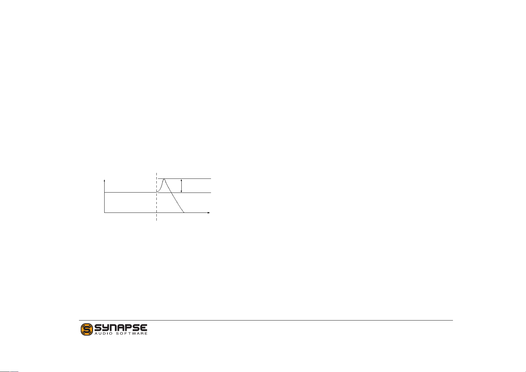
GATE/ACCENT
Time
Note On
Note Off
Amount
Time
Amount
Accent On
Gate
Accent
The arpeggiator constantly emits a gate and an accent
signal. The Gate signal is by default in low state, and
goes high for the duration of a note.
The accent signal is by default in low state as well,
and goes high on every accented step. Usually, every note is accented, but some of the preset patterns
contain separate note and accent data. The most important difference between Gate and Accent is their
shape, however. The accent shape has a soft slope,
which is useful for growling bass sounds. The gate has
a more abrupt shape, and is useful to chop a sustained
sound into a rhythmic pattern.
Figure 5.1: Gate and Accent.
34 Antidote User’s Manual

Sequencer In
6 Back Panel
The back panel hosts the audio and CV connections
for Reason. A good understanding of how CVs work
in Reason will enable you to obtain mind-blowing results with Antidote, and is obligatory to build complex
patches which would otherwise exceed the functionality provided. A simple example is a patch requiring a
third LFO. You can add one easily by connecting an
external LFO to one of Antidote’s CV inputs, then assign this CV input via Antidote’s modulation matrix.
CV Inputs
Antidote RE has four CV inputs, which can be freely
used as modulation sources in the modulation matrix.
Allows to connect Reason’s step sequencers (such as
Matrix, RPG-8, or Thor’s) to trigger monophonic note
sequences using Gate/CV signals. Make sure to connect both the gate and CV cable.
Arp Out
Sends notes from Antidote’s arpeggiator to other Reason devices, in the Reason-specific Gate/CV form.
Ext Input
A pair of audio inputs, which allow you to connect
other stereo devices to Antidote and take advantage
of Antidote’s superior-quality effect chain. The input
signal is mixed with Antidote’s synthesizer output just
before the first effect (EQ/Bass). The input level can
be controlled and automated on the front side of the
plugin.
Modulation CV Inputs
Standard Reason CV inputs, which are fixed to Pitch
Bend, Modulation Wheel and Amplitude. Reason will
automatically connect those CV inputs in some cases.
Output
Antidote’s stereo output.
35 Antidote User’s Manual

Configuration
The configuration section sets the pitch wheel
up/down range, as explained in the second chapter.
Furthermore, the MIDI key velocity can be routed to
the volume, panorama and filter cutoff parameters.
While this could be done via the modulation matrix,
using the knobs is faster, and saves modulation slots
for other purposes.
36 Antidote User’s Manual

7 MIDI Reference
Most knobs and buttons on the front panel can be
remote controlled via MIDI. Antidote’s default controller assignments follow common conventions and
the MIDI standard as much as possible. The number of sound parameters Antidote offers, however, is
higher than the amount of available MIDI controllers.
Effect parameters are thus outside the MIDI range.
Antidote Parameter CC #
Polyphony 15
Master Volume 7
Glide 5
Ext Input Amount 4
Osc 1 Semi 78
Osc 1 Fine 79
Osc 1 Detune 80
Osc 1 Spread 81
Osc 1 Phase 82
Osc 1 Modifier 25
Osc 1 Key Track 36
Antidote Parameter CC #
Osc 1 Pan 37
Osc 1 Waveform 13
Osc 1 Voices 23
Osc 1 Dyad 33
Osc 2 Semi 83
Osc 2 Fine 84
Osc 2 Detune 85
Osc 2 Spread 86
Osc 2 Phase 87
Osc 2 Modifier 35
Osc 2 Key Track 76
Osc 2 Pan 77
Osc 2 Waveform 14
Osc 2 Voices 24
Osc 2 Dyad 34
Osc 1 Volume 8
Osc 2 Volume 9
Sub 1 Volume 10
Sub 2 Volume 12
Drift 70
Filter Type 44
Filter Cutoff 74
Filter Resonance 42
Filter Envelope Amount 43
Filter Key Track 46
Filter Envelope Attack 47
Filter Envelope Decay 48
37 Antidote User’s Manual

Antidote Parameter CC #
Filter Envelope Sustain 49
Filter Envelope Release 50
Mod Envelope Attack 26
Mod Envelope Decay 27
Mod Envelope Sustain 28
Mod Envelope Release 29
Mod Envelope Target 30
Mod Envelope Target Amount 31
Amp Envelope Attack 73
Amp Envelope Decay 75
Amp Envelope Sustain 71
Amp Envelope Release 72
Lfo 1 Rate 19
Lfo 1 Rate Sync 18
Lfo 1 Shape 20
Lfo 1 Sync 16
Lfo 1 Free Run 17
Lfo 1 Target 21
Lfo 1 Target Amount 22
Lfo 2 Rate 52
Lfo 2 Rate Sync 51
Lfo 2 Shape 53
Lfo 2 Sync 56
Lfo 2 Free Run 57
Lfo 2 Target 54
Lfo 2 Target Amount 55
Arp Mode 68
Arp Hold 69
Antidote Parameter CC #
Arp Pattern 60
Arp Octave 61
Arp Rate 62
Arp Gate 63
MM Slot 1 Source 105
MM Slot 1 Amount 106
MM Slot 1 Destination 107
MM Slot 2 Source 108
MM Slot 2 Amount 109
MM Slot 2 Destination 110
MM Slot 3 Source 111
MM Slot 3 Amount 112
MM Slot 3 Destination 113
MM Slot 4 Source 114
MM Slot 4 Amount 115
MM Slot 4 Destination 116
MM Slot 5 Source 117
MM Slot 5 Amount 118
MM Slot 5 Destination 119
EQ/Bass Active 93
Distortion Active 94
Phaser Active 124
Chorus Active 125
Delay Active 126
Reverb Active 127
Compressor Active 94
EQ Low Gain 129
38 Antidote User’s Manual

Antidote Parameter CC #
EQ Mid Freq 130
EQ Mid Q 131
EQ Mid Gain 132
EQ High Gain 133
Bass Freq 134
Bass Amount 135
EQ/Bass Dry/Wet 136
Distortion Type 137
Distortion Drive 138
Distortion Symmetry 139
Distortion Tone 140
Distortion Low Cut 141
Distortion High Cut 142
Distortion Level 143
Distortion Dry/Wet 144
Phaser Freq 145
Phaser Spread 146
Phaser Feedback 147
Phaser Rate 148
Phaser Mod 149
Phaser LR Offset 150
Phaser Dry/Wet 151
Chorus Delay 152
Chorus Rate 153
Antidote Parameter CC #
Chorus Depth 154
Chorus Feedback 155
Chorus LR Offset 156
Chorus Dry/Wet 157
Delay Type 158
Delay L-Rate 159
Delay R-Rate 160
Delay Color 161
Delay Feedback 162
Delay Mod Rate 163
Delay Mod Amount 164
Delay Dry/Wet 165
Reverb Pre-Delay 166
Reverb Time 167
Reverb HF Damp 168
Reverb Low Cut 169
Reverb High Cut 170
Reverb Mod 171
Reverb Dry/Wet 172
Compressor Ratio 173
Compressor Threshold 174
Compressor Attack 175
Compressor Release 176
Compressor Dry/Wet 177
39 Antidote User’s Manual

Credits
Copyrightc Synapse Audio Software 2012.
All rights reserved.
Concept: Daniel Thiel
Programming and Manual: Richard Hoffmann
Graphic Design: Marcin Lezak
Sound Design
The last two characters of every patch name are the
author’s initials. The following table lists all sound
designers who contributed patches to Antidote, and a
website where you can learn more about their work.
Ab. Author Name Website
EX eXode (Daniel Thiel) www.soundcloud.com/exodesound
KD Koshdukai (Marco C.) www.KoshdukaiMusicReason.blogspot.com
MG Mike Gorman www.combinatorhq.com
MK Michael Kastrup www.xsynth.com
OR David Orbel www.orbelmusic.com
RH Richard Hoffmann www.synapse-audio.com
SH Sasha Radojevic www.phuturetone.com
SC Soundcells (Harald Karla) www.soundcells.de
40 Antidote User’s Manual
 Loading...