

Page 1
Safety by Design
OPERATION MANUAL
Radiator Coolant
Service Center
Revision: 06/12/12
Page 2

Table of Contents
Introduction………………………………………………………………………………………………….2
Safety Precautions……………………………………………………………………………………………3
System Functional Components…………………………………………………………………………….4
Before Starting………………………………………………………………………………………………4-5
Control Panel Descriptions and Functions………………………………………………………………...7
Pressure Relief Procedure…………………………………………………………………………………..7
Drain and Fill versus Reverse Flush……………………………………………………………………….8
DRAIN AND FILL EXCHANGE
Draining Cooling System .............................................................................................................................9
Vacuum Leak Testing and Filling Cooling System ...................................................................................10
Topping off Cooling System ........................................................................................................................10
REVERSE FLUSH
Connection Possibilities ...............................................................................................................................11
1) Traditional Flow……………………………………………………………………….…….……..11
2) Reverse Flow…………………………………………………………………………..……………11
3) Thermostat…………………………………………………………………………...……………..11-12
4) Coolant Reservoir, Pressure Cap……………………………………………..………………….12
REVERSE FLUSH PROCEDURE – Traditional Flow Cooling System
1) Lower Coolant Level………………………………………………………………………………12
2) Adapter Set-Up…………………………………………………………………………….………13
3) Pressure Test……………………………………………………………………..…...…………….13
4) Exchange……………………………………………………………..………………..……………13
5) Disconnecting……………………………………………………………………….………………14
6) Topping Off…………………………………………………………………………………...…….14
Changeover of PRIMARY (internal) Coolant Tank to ALTERNATE (external) Coolant Tank ..........15
Changeover of ALTERNATE (external) Coolant Tank to PRIMARY (internal) Coolant Tank ..........16
Empty Used Coolant ....................................................................................................................................17
Empty Tool Reservoir ..................................................................................................................................17
Troubleshooting ...........................................................................................................................................18
Statement / Commitment .............................................................................................................................19
1
Page 3

Introduction
Safety by Design
Thank you for purchasing Symtech Corporation’s VFX 1 Radiator Coolant Service System. The VFX 1 is a
very simple yet effective machine design to quickly perform all required periodic maintenance services for
automotive cooling systems. It is extremely easy to operate, environmentally safe, and designed for the
greatest speed and efficiency.
The Operations Manual MUST be read and COMPLETELY UNDERSTOOD in order to properly operate
the unit and experience the highest return on investment. Refer to the manual in the future for continued safe
operation. If you encounter difficulties in the operation, understanding of procedures, or have general
service questions, please do not hesitate to call us at 888-884-8182.
Please record the purchase date, serial number and distributor purchased from below for future reference and
assistance in technical issues.
Purchase Date: _______________________
Serial Number: _______________________
Purchased From: __________________________________
__________________________________
__________________________________
V1-
Located on Back of Unit
TECHNICAL SUPPORT
1-888-884-8182
Central Standard Time
8AM to 5PM, Monday through Friday
2
Page 4
SAFETY PRECAUTIONS
WARNING: FAILURE TO FOLLOW PRECAUTIONS CAN RESULT IN INJURY OR DEATH
Always use extreme caution and forethought when servicing automotive systems! Automotive systems
are extremely hot and contain high pressure.
Always read and understand the entire Operations Manual before operating!
Always wear proper eye and skin protection when operating equipment!
Always keep fire extinguisher nearby for flammable conditions!
Always keep hair, loose clothing, hoses, etc. securely away from moving parts!
Always keep work area well ventilated to prevent carbon monoxide build up!
Always comply with local, state, and federal regulations concerning fluid disposal!
Always clean up and report spill in a proper manner!
Always read and understand the Material Safety Data Sheets (MSDS) for particular fluids!
Always seek emergency medical attention for ingestion of, or eye contact with fluid!
Always replace radiator cap after performing “Lower Coolant Level” function!
Do not use harsh cleaners such as thinners or petroleum based solvents to clean the unit and or unit
components. Certain harsh chemicals can negatively affect the durability and appearance – only use mild
cleaners.
Periodically, inspect the hoses and cone of the VFX 1 for normal wear or damage. Contact Symtech for
replacement components.
WARNING: Cooling systems can be under extreme pressure – extra care must be taken to properly
protect against accidental releases of hot, pressurized coolant.
WARNING: Do not modify or alter the unit in any manner whatsoever. Modification of the unit to
perform unspecified actions can endanger personnel and or damage the vehicle and unit!
WARNING: Never point the cone at self or other personnel while operating the unit!
WARNING: HOSE CONNECTIONS AND FITTINGS CAN BECOME EXTREMELY HOT DURING
COOLANT FLUSH AND VACUUM DRAIN AND FILL OPERATIONS, CAUTION
MUST BE TAKEN WHEN HANDLING FITTINGS!! WEAR GLOVES OR USE OTHER
MEANS TO SHIELD AGAINST INJURY!!
WARNING: TAKE NECESSARY PRECAUTIONS TO SECURE THE VEHICLE WHEN
PERFORMING COOLANT SERVICES!!
3
Page 5
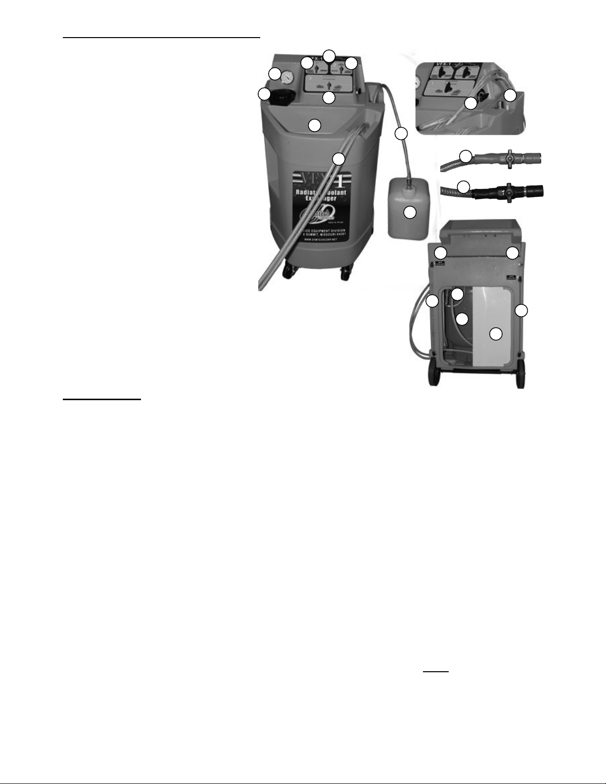
VFX 1 System Functional Components
FRONT:
1. CONTROL PANEL
1A. AIR CONTROL VALVE
1B. FUNCTION CONTROL VALVE
1C. FLUID CONTROL VALVE
2. PRESSURE GAUGE
3. NEW FLUID FILL CAP
4. NEW FLUID TANK SELECTOR
5. NEW AND USED FLUID
HOSES
6. NEW FLUID
7. NEW FLUID
8. EXTRACTION PORT, TOOL STORAGE
COMPARTMENT DRAIN RESERVOIR.
9. RED/ NEW COOLANT FLOW CONTROL
VALVE
10. BLACK/USED COOLANT FLOW CONTROL
VALVE
11. TOOL STORAGE COMPARTMENT
REAR:
1. NEW FLUID TANK SIGHT GAUGE
2. USED FLUID TANK SIGHT GAUGE
3. SHOP AIR CONNECTION
4. INLINE FILTER
5. SERIAL NUMBER PLATE
6. 5 GALLON
7. 15 GALLON USED FLUID TANK
ALTERNATE
ALTERNATE
TANK CONNECTION
TANK
PRIMARY (INTERNAL)
NEW FLUID TANK
2
3
1A
11
1
1C
1B
4
6
5
7
1
9
10
5
4
7
6
Before Starting
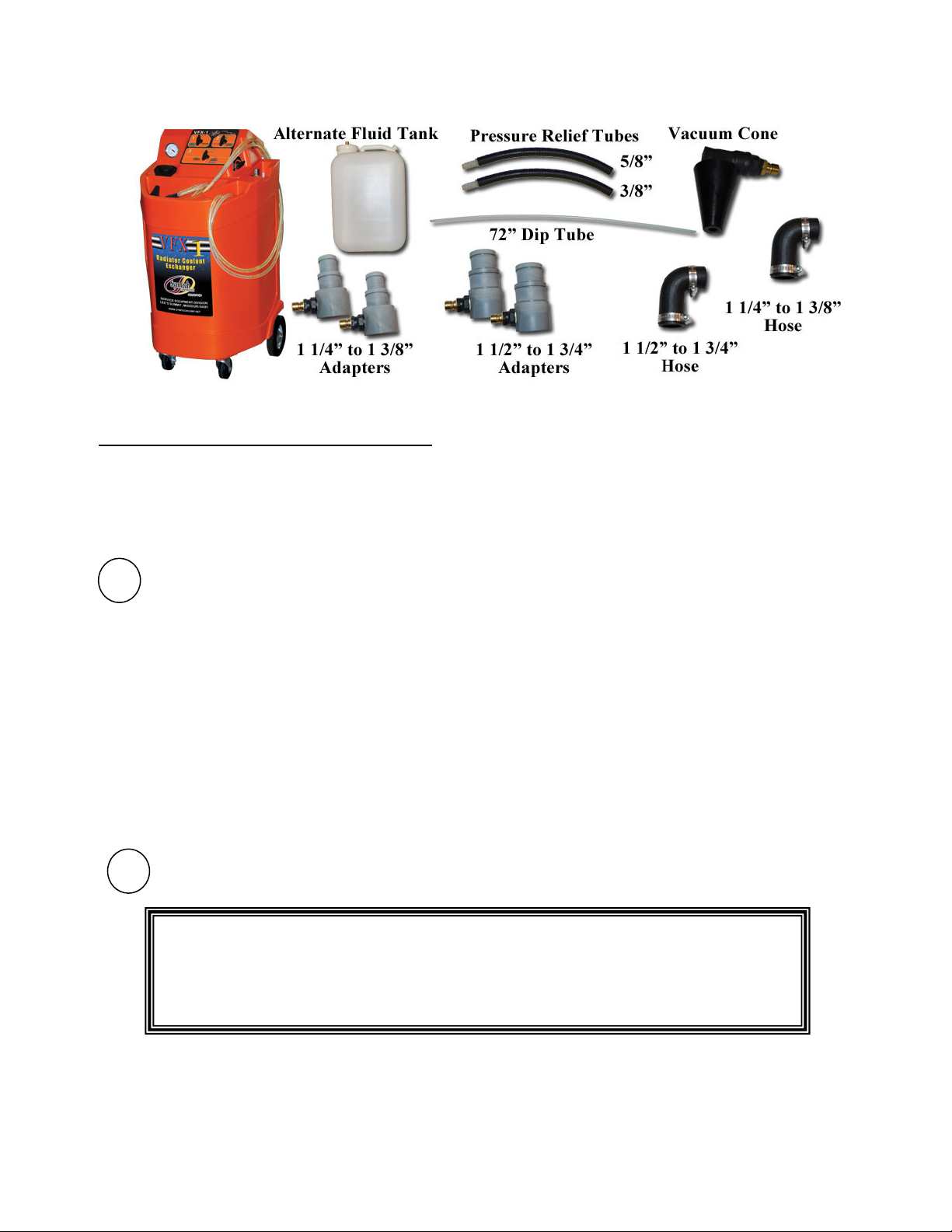
1) Upon unpacking the VFX 1 verify all components as depicted below are included. Contact Symtech if any
NOTE: NEVER over fill PRIMARY (internal) New Fluid Tank, doing so could cause a small amount of
NOTE: NEVER put anything but coolant and water mix in the new coolant tank of the VFX 1. If A
NOTE: NEVER put any type of STOP LEAK into New Fluid Tank, STOP LEAK will clog filters,
NOTE: Always test the freeze point of coolant after exchange is complete to verify the coolant offers
components are damaged or missing.
2) Thoroughly read manual and become familiar with control panel and components!
3) Prepare appropriate mixture of water and vehicle specified type of coolant in the new fluid container.
Always use specified coolant per vehicle manufacturer’s specification or vehicle owner’s manual. The
VFX 1 is shipped standard with “1”, PRIMARY (internal) and “1” ALTERNATE (external) 5-gallon new
coolant tanks. Additional tanks can be ordered from Symtech as required.
4) Verify that all valves are in the correct position – see information on control panel valves and verify flow
control valves located at hose ends are closed to avoid accidental operation or spills. (See Pg 5-7)
5) Connect the VFX 1 to clean shop air supply – minimum constant pressure of 70psi and maximum pressure
of 120psi. Shop air must be filtered clean air as debris may impact performance of the unit.
6) The VFX 1 is now ready to perform coolant fluid exchanges.
fluid to seep out of the overflow tube, leaving traces of fluid in bottom of VFX 1 case.
CHEMICAL cooling system flush is to be used, it should be added and circulated in the cooling
system prior to exchange functions being performed.
fittings and hoses. Placing STOP LEAK into the new fluid tank will VOID warranty and result
in excessive repairs.
proper protection for geographic area.
8
3
2
4
Page 6
Control Panel Descriptions and Functions
The following information is intended to familiarize the VFX 1 operator with the control panel and its
functions. Time must be taken to read and understand the VFX 1 controls and operation for safe and acceptable
performance of the unit. All control panel valve functions are color coded to aid technician in the function
selection process. Simply match all three control panel valves to the matching colored function legends at each
control panel valve - #1, #2, and #3. Please refer to diagram on next page for full details.
1
AIR CONTROL
OFF position stops all air flow – valve should always be returned to the OFF position after completion
(PRESSURE) – FLUSH
(VACUUM) DRAIN AND FILL
2
FUNCTION CONTROL
THIS VALVE SHOULD ALWAYS BE DIRECTED TO FLUSH (BLUE) TO SAVE
A STEP IN MOST CASES AND TO LEAVE THE USED COOLANT TANK AT
ATMOSPHERIC PRESSURE. THE FUNCTION CONTROL VALVE ONLY
NEEDS TO BE ADDRESSED WHEN EMPTY USED, TOP-OFF, OR HOLD
FUNCTIONS ARE REQUIRED TO BE PERFORMED.
HOLD, TOP OFF
–
Controls supplied shop air pressure flow and is the first step in exchange process
(BLUE)
This position directs shop air pressure to the new fluid pump. Allowing user to perform
reverse FLUSH, top off, and EMPTY USED fluid tank procedures.
(RED)
shop air pressure to vacuum venture where vacuum is created then stored within the
onboard tank. . Allowing the user to perform the vacuum DRAIN & FILL, and LOWER
LEVEL procedures
–
Controls pressure or vacuum flow to used coolant tank and is the second step
of the process.
(GREEN)
fluid tank, preventing air pressure from reaching used tank during TOP OFF procedure.
– This Position stops the vacuum or pressure flow to and from the used
of each function. Automatic pressure relief of new fluid hose
occurs when in the off position.
, TOP OFF
(GREEN) ,
, LOWER LEVEL
EMPTY USED
(YELLOW)
(PURPLE)
, – This position directs
, –
.
5
Page 7

FLUSH
EMPTY USED
(BLUE)
, DRAIN AND FILL
diverts generated vacuum to the used coolant tank where it is stored, allowing the user to
extract used coolant from vehicle during the DRAIN & FILL and LOWER LEVEL
procedures. This position also prevents pressure build up in used fluid tank during
FLUSH procedure.
(PURPLE)
fluid tank to ultimately force used coolant from the used fluid tank.
– This position allows internally regulated air pressure to build in used
(RED) ,
LOWER LEVEL
(YELLOW)
, – This position
3
FLUID CONTROL
OFF/ PRESSURE TEST – This position stops all coolant flow to and from vehicle, isolating vehicle
NEW- TOP OFF
USED- FLUSH
This position Allows used coolant flow to the used coolant storage tank during FLUSH, DRAIN, and
–
Controls coolant flow to and from machine and/or vehicle depending upon function
selected.
from machine for pressure testing procedure.
(GREEN),
tank to vehicle’s coolant system.
(BLUE)
LOWER LEVEL procedures. This position also allows user to perform the standard
EMPTY USED tank procedure
FILL
, DRAIN
(RED)
(RED)
, LOWER LEVEL
– Allows new coolant to flow from selected new fluid
(YELLOW)
, EMPTY USED
(PURPLE)
,
6
Page 8

Figure 1
Figure 5
Figure 4
Figure 2
Figure 3
FLOW CONTROL VALVES
The flow control valves at the end of the RED/NEW and BLACK/USED
hose ends should always be in the closed position until desired function is
ready to be performed. This prevents accidental operation or spills until
technician is ready to remove and/or add coolant.
WARNING: HOSE CONNECTIONS AND FITTINGS CAN BECOME EXTREMELY HOT
DURING COOLANT FLUSH AND VACUUM DRAIN AND FILL OPERATIONS,
CAUTION MUST BE TAKEN WHEN HANDLING FITTINGS!! WEAR GLOVES
OR USE OTHER MEANS TO SHIELD AGAINST INJURY!!
CONTROL VALVE, PRIMARY (INTERNAL) / ALTERNATE (EXTERNAL)
NEW FLUID COOLANT TANK(S)
Coolant Tank Control Valve, switches between the PRIMARY
(internal) coolant tank and an ALTERNATE (external) coolant tank,
the OFF position is used only when servicing the PRIMARY (internal)
coolant filter.
Pressure Relief Procedure
The Pressure Relief procedure is designed to allow immediate servicing of “HOT
VEHICLES” by alleviating cooling system pressure versus waiting for vehicle to cool
down. EXTREME CARE must still be taken as hot coolant can cause injury.
1) Verify adequate capacity for used fluid in used fluid sight gauge. Refer to
EMPTY USED coolant section to empty used coolant tank.
2) Properly secure vehicle against accidental movement.
3) Verify all VFX 1 Control panel valves are in the neutral position, AIR
CONTROL Valve #1, OFF, FUNCTION CONTROL Valve #2, HOLD, and
FLUID CONTROL Valve #3, OFF. (Fig 1)
4) Connect clean shop air supply (70-120psi).
5) Turn AIR CONTROL valve (#1) FUNCTION CONTROL valve (#2) and
FLUID CONTROL valve to the right, LOWER LEVEL (
(Fig 2) Vacuum will begin to build on the compound gauge.
YELLOW
).
6) Insert rubber “pressure relief hose” into opening of cone. (Fig 3) Connect
cone assembly to BLACK/USED coolant hose and open used flow control
valve.
7) Remove cooling system overflow tube or hose from radiator neck or
Remote Reservoir tank, (Fig 4). Securely connect rubber hose extension to
overflow tube. Note: The rubber hose extension can be omitted and the
cone opening can be placed directly on large overflow tubes.
8) Slowly open radiator or Remote Reservoir cap observing vacuum level.
Upon “cracking” seal, used coolant will be extracted through overflow tube
creating a low pressure area behind the system’s cap.
9) When no used coolant is observed flowing through the clear hose and a
vacuum of at least 15” is reached, the radiator or Remote Reservoir cap can
be safely removed.
10) Once cap is removed return all control panel valves to neutral position and
flow control valves at hose ends OFF. (Fig 5)
7
Page 9

DRAIN and FILL
(RED)
versus REVERSE FLUSH
(BLUE)
The VFX 1 Coolant exchange system offers two methods to easily perform coolant exchanges: DRAIN AND FILL
(RED)
types, and the advantages and disadvantages of each.
DRAIN AND FILL
REVERSE FLUSH
Both types of exchanges are easily performed by simply following the colored control panel valve sequence.
and REVERSE FLUSH
(RED)
to pull used coolant from the vehicle’s cooling system via the radiator cap or Remote Reservoir tank opening.
The resultant vacuum created in the vehicle’s cooling jacket is in turn used to pull in new coolant.
ADVANTAGES of the DRAIN AND FILL
cooling system is easily accessed. Shop mess is minimized as the coolant system remains intact and
air pockets are eliminated from the cooling system by the vacuum level reached during extraction.
DRAIN AND FILL does not involve adapters or in-depth knowledge of cooling systems.
DISADVANTAGES of a DRAIN AND FILL
Some coolant system configurations do not allow a large percentage of used coolant to be evacuated
via vacuum and the exchange process may produce inferior results. Many times the DRAIN AND
FILL procedure can be repeated to obtain acceptable results, but this may be inefficient and more
costly than reverse flushing.
(BLUE)
the upper radiator connection, flushing backwards through the engine block, and up through the radiator forcing
the used coolant out into the unit’s used coolant tank. Some systems have reverse flow cooling systems and the
new coolant may flush through the radiator first, then the engine block and out.
ADVANTAGES; The REVERSE FLUSH
effective method as the backwards flow of new coolant purges the old coolant and most debris out of
the system. Less new coolant is used to achieve excellent results.
DISADVANTAGES; A REVERSE FLUSH
via adapters and hoses. This sometimes requires more time to perform exchange, creates air pockets
that will need to be “burped” from the vehicle, and there is more potential for spillage of coolant than a
DRAIN AND FILL service. The REVERSE FLUSH exchange also requires a more in depth
understanding of cooling system flow and operation.
(BLUE)
- entails using shop air pressure to create vacuum in the VFX 1. This vacuum is then used
– utilizes pressurized new coolant entering the vehicle’s cooling system, usually through
. The following information describes the basic differences between the two
(RED)
(BLUE)
(BLUE)
exchange are; speed, simplicity, and ease of use as the
(RED)
coolant exchange is less efficient on some vehicles.
coolant exchange process is the most efficient and
exchange requires breaking into the cooling system
8
Page 10

DRAIN AND FILL EXCHANGE (
Figure 1
Figure 3
Figure 2
Figure 4
Draining Cooling System
1) Verify Pressure Relief Procedure described above has been performed.
2) Verify adequate capacity for used fluid with used fluid sight gauge. Refer to
EMPTY USED coolant section to empty used coolant tank.
3) Turn AIR CONTROL valve (#1) FUNCTION CONTROL valve (#2) to the
right, DRAIN-N-FILL (
right, DRAIN (
(Fig 2)
4) Insert longest nylon tube extension into small cone opening. Connect cone
assembly to BLACK/USED coolant hose. (Fig 2)
5) Insert extension tube into overflow tank. The extension tube should reach
the bottom of the overflow tank. Do not allow cone to seat on plastic
overflow tanks.
6) Open BLACK/USED coolant flow control valve. Used coolant will be
removed. Completely empty the overflow tank.
7) Close BLACK/USED coolant flow control valve.
8) Insert cone tip into radiator neck or coolant reservoir tank opening (see note
below) and open BLACK/USED coolant flow control valve. The vacuum
will securely seat and seal the cone into the opening and used coolant will
begin to be extracted from the cooling system. (Fig 3)
RED
RED
). Vacuum will begin to build on the compound gauge.
NOTE: The RED/NEW coolant hose is not used to perform
a DRAIN AND FILL (RED) coolant exchange.
), and FLUID CONTROL valve (#3) to the
RED
)
Note: For better exchanges, insert the longest possible nylon tube extension into the radiator or
coolant reservoir tank, being extremely careful not to force the tube or damage the internals of
the radiator or coolant reservoir tank. Once the longest possible nylon tube extension has been
determined insert the extension securely into the cone. This “longer dip-tube assembly” will
allow more of the used coolant to be removed from the system versus no dip-tube assembly.
Note: Some radiator neck openings are shallow – internal components such as the core or
supports are in close proximity to the opening. The neck may be so shallow that the
cone will bottom out on the core or internal supports preventing the cone to seal on
the radiator neck. Trimming or cutting back the narrow end of the cone to the
required diameter may be necessary to acquire a leak proof seal.
9) Once cone is securely seated, start vehicle and observe used coolant
hose and vacuum gauge. When fluid stops flowing and the vacuum
gauge has reached at least 20in vacuum, turn off vehicle!
WARNING; be careful not to overheat the vehicle by running
the vehicle too long!!
WARNING; Fittings can become extremely hot during
DRAIN / FILL exchange.
10) Do not remove cone from system!! Vacuum reached in cooling
system is used to “pull in” new coolant. If cone is removed, or seal is
lost, the vacuum must be restored to remove air from system and
allow new coolant to be pulled into the vehicle’s cooling system.
11) Return AIR CONTROL valve #1 and FLUID CONTROL valve #3
to OFF position. Turn FUNCTION CONTROL valve #2 to HOLD
position. ( Fig 4)
9
Page 11

Figure 5
Figure 1
Figure 2
Figure
3
Figure
4
Figure
6
Vacuum Leak Testing Cooling System (This test can only be performed on cool engines)
While the cooling system is in a “trapped vacuum condition” from the Draining Cooling System procedure above,
the vacuum level can be recorded and checked over a period of time, usually two minutes. If the vacuum level
decreases, there may be a leak in the cooling system. Although pressure testing is the preferred leak test method, this
quick test will indicate large leaks requiring immediate attention before introducing new coolant into a leaking
system.
Filling Cooling System
1) Upon completion of “Draining” procedures, the cooling system can be refilled.
2) Verify the system still maintains at least 20inHg vacuum after “Draining” steps.
3) Verify adequate amount of new coolant in new coolant tank to perform refill.
4) Turn FLUID CONTROL valve (#3) to the left, FILL (
5) Return all control panel valves to neutral position, (Fig 6) and BLACK/USED
Topping Off Cooling System
1) Verify all control panel valves are in neutral position.
2) Turn AIR CONTROL valve (#1) and FLUID
3) Connect cone assembly to RED/NEW coolant flow control valve. (Fig 3)
4) Place vacuum cone into radiator or Remote Reservoir neck. Slowly open
(Fig 3)
5) Close RED/NEW coolant flow control valve when proper coolant level is
6) Fill overflow tank to proper level following the procedures described in
7) Return all control panel valves to neutral position. (Fig 4)
8) Replace radiator / remote reservoir, and overflow caps.
The vehicle’s engine continues to run during this procedure.
If the system vacuum is inadequate, drain system steps will need to be repeated
to re-establish required vacuum level to pull-in new coolant. Refer to “Draining
Cooling System”
RED
). New coolant will
flow into vehicle’s cooling system until vacuum equalizes. Completion of this
step is signified when new coolant flow ceases and vacuum gauge reaches “-3 ~
-5 inHg”. (Fig 5)
coolant flow control valve at hose end OFF.
(Fig 1) Turn both flow control valves at hose end OFF.
CONTROL Valve (#3) to the left, TOP OFF (
FUNCTION CONTROL valve (#2) straight up, TOP
OFF (
GREEN
). (Fig 2)
RED/NEW coolant flow control valve, observing coolant fluid level.
reached.
steps 4 and 5.
GREEN
),
10
Page 12

REVERSE FLUSH EXCHANGE (
a Reverse Flush exchange!!
The vehicle remains
OFF
during the entire Reverse Flu
sh
BLUE
)
NOTE: Before Starting, Control Panel Descriptions and Functions must be read and
understood. If vehicle is hot, Pressure Relief procedures must be performed before attempting
Connection Possibilities
Reverse Flush exchanges entail opening the cooling system up at either end of the upper radiator hose connection via
step adapters and adapter hoses of the appropriate size, connect the VFX 1 new and used coolant lines to the installed
adapters and flush the used coolant out via new coolant being introduced. There are three possible connection scenarios
to achieve the proper flow direction to successfully perform the exchange and each scenario must be tried in the
following order:
1. TRADITIONAL FLOW - Most vehicles have
traditional coolant flow – coolant flows downward
through the radiator, pulled by the water pump
through the lower radiator hose, pushed through the
engine block water jacket, upward through the heads
and intake, out the thermostat (if engine is to normal
operating temperature) and back to the radiator to
repeat the process via upper radiator hose. Please
refer to diagram.
To Reverse Flush this type system, the upper radiator
hose is disconnected, and new coolant is introduced
via adapters and adapter hoses against the “backside”
of the thermostat. The pressure of the new coolant
forces open the thermostat and flows backwards from
normal flow “pushing” the used coolant and debris
through the cooling system and out the upper radiator
hose into the used fluid tank of the VFX 1.
NOTE: After connecting unit for Traditional Flow, if new coolant pump DOES NOT pulsate and used coolant IS NOT
flowing from radiator to unit, RECHECK all connections, control panel valves, and flow control valves for
correctness and RETRY. IF problem persists, the vehicle’s cooling system is a REVERSE FLOW SYSTEM
or THE THERMOSTAT WILL NOT OPEN FROM THE BACK SIDE.
2. REVERSE FLOW – Reverse Flow cooling systems circulate in the opposite direction of traditional systems,
because the thermostat is located in the bottom of the engine block. This means coolant flows up through the
radiator, through the upper radiator hose connection, into the top of the engine block, downward through the
engine block, through the thermostat (if the engine is at operating temperature), and back to the lower radiator via
lower radiator hose for re-circulation.
To Reverse Flush these vehicles follow the same procedures as a Traditional Flow flush, LOWER LEVEL,
ADAPTER SET-UP, However reverse the connection of the coolant flow control valves. Connect the
RED/NEW coolant flow control valve to the upper radiator hose adapter and the BLACK/USED coolant
flow control valve connected to the engine block outlet adapter.
PRESSURE TEST, DISCONNECTING, and TOPPING OFF procedures remain the same once the fluid
exchange is complete.
IF Reverse Flow connection is attempted and new coolant pump STILL DOES NOT pulsate and used
coolant IS NOT flowing from engine block to unit, RECHECK all connections, control panel valves, and
flow control valves for correctness and RETRY. IF problem persists, refer to third connection procedure
below.
3. THERMOSTAT – The third connection option is utilized only when TRADITIONAL and REVERSE methods
do not work. The third option does not allow for a reverse flush, but does allow a coolant fluid exchange. Follow
the same procedures as a Traditional Flow flush, LOWER LEVEL, ADAPTER SET-UP, however reverse the
connection of the coolant flow control valves as described in Reverse Flow (#2), with the RED/NEW coolant
11
Page 13

flow control valve connected to the upper radiator hose adapter and the BLACK/USED flow control valve
Figure 1
Figure 2
Figure 3
Figure 4
connected to the engine block outlet adapter.
The vehicle is started and allowed to reach normal operating temperature which allows the thermostat to open
allowing coolant to flow from the unit through the cooling system and back into the unit. The coolant is flowing
as normal when operating temperature is reached, but the unit is in the loop receiving used coolant as it is pumped
out and injecting new coolant in its place.
The flow may stop and start intermittently, as the new coolant cools the thermostat, closing the thermostat until
normal operating temperature is reached, re-opening the thermostat and flow resuming.
PRESSURE TEST, DISCONNECTING, and TOPPING OFF procedures remain the same once the fluid
exchange is complete.
4. RESERVOIR TANK, PRESSURE CAP: Systems that do not have a pressure cap on the radiator will in most
cases have a pressure cap on a Remote Reservoir Tank. In those instances it will be necessary to pinch closed the
hoses to the reservoir tank during the coolant exchange.
If hoses are not pinched closed, it is possible for coolant to be forced out of pressure cap and also the coolant
exchange will not be an entire system flush as coolant is routed around the engine and through the reservoir.
COMPLETE THE FOLLOWING STEPS TO REVERSE
FLUSH A TRADITIONAL FLOW COOLING
SYSTEM:
LOWER LEVEL
The LOWER LEVEL
the upper radiator connection by lowering the coolant level below the disconnection point.
1) Verify adequate amount and type of new coolant to complete exchange is in new
coolant tank.
2) Verify adequate capacity for used fluid in used fluid sight gauge. Refer to
EMPTY USED coolant section to empty used coolant tank.
3) Verify that all VFX 1 Control panel valves are in the neutral position, (Fig 1)
and flow control valves at hose ends are off.
4) Connect clean shop air supply (70-120psi).
5) Turn
AIR CONTROL
CONTROL
(Fig 2). Vacuum will begin to build on the compound gauge.
6) Connect vacuum cone with extension tube to BLACK/USED coolant hose and
open BLACK/USED coolant flow control valve at hose end. (Fig 3)
7) Insert vacuum cone with extension tube into overflow tank and remove all used
coolant from tank. Do not seat cone into overflow tanks opening.
8) Remove radiator cap – Has Pressure Relief Procedure been performed? insert vacuum cone with extension tube being careful not to damage radiator
components.
9) Lower coolant level as far as possible by observing used coolant flow in hose.
10) When used coolant flow ceases, close used coolant flow control valve at hose
end.
11) Return all control panel valves to correct neutral position, (Fig 4) and flow
control valves at hose ends off.
12) REPLACE RADIATOR CAP.
(YELLOW)
procedure is intended to reduce coolant spillage created when disconnecting
valve (#1) FUNCTION CONTROL, valve (#2)
Valve and valve (#3) to the right LOWER LEVEL (
FLUID
YELLOW
),
12
Page 14

ADAPTER SET-UP
Figure 1
Figure 2
Figure 3
Figure 1
Figure 2
Figure 3
1)
Disconnect the upper radiator hose at most accessible point.
2) The appropriate size adapter hose along with its matching step adapter is
installed on the exposed outlet neck and secured with correct hose clamps.
3) The tightest fitting step adapter is next installed and secured by hose clamps to
the vehicle’s exposed radiator hose making sure the connection plugs are
accessible.
4) Connect the RED/NEW coolant flow control valve to the step adapter leading to
the thermostat or engine block.
5) Connect the BLACK/USED coolant flow control valve to the step adapter
leading to radiator.
PRESSURE TEST
A cooling system pressure test to detect leaks in the cooling system can be performed using
the VFX 1. Care must be taken not to over pressurize the system during this test and the
radiator cap must be in proper working order to act as a safety outlet for excessive pressure.
1) Turn AIR CONTROL valve (#1) Left, FUNCTION CONTROL valve (#2)
Right, and FLUID CONTROL valve (#3) OFF / PRESSURE TEST. (Fig 1)
2) Open BLACK/USED coolant flow control valve and VERY SLOWLY, open
RED/NEW coolant flow control valve at hose end, observing increasing
pressure on compound gauge.
3) When desired system pressure is obtained (usually 1-2lb below specified system
pressure), turn RED/NEW coolant flow control valve at hose end off.
4) Observe pressure gauge for two minutes – pressure should not drop.
5) If pressure drops, investigate for leaks, resolve, and retest.
6) If no pressure loss is observed, return all control panel valves to neutral position,
(Fig 3) and flow control valves at hose ends to off.
EXCHANGE
(BLUE)
1) Verify all VFX 1 Control panel valves are in the neutral
position, (Fig 1) and flow control valves at hose ends are off.
2) Turn AIR CONTROL valve (#1) to the left, FLUSH (
BLUE)
and FUNCTION CONTROL valve (#2) and FLUID
CONTROL valve (#3) to the right, FLUSH (
Pressure will begin to build on the compound gauge.
3) Open both RED/NEW and BLACK/USED coolant flow control valves.
BLUE
). (Fig 2)
4) The new coolant pump will pulsate and new coolant should be flowing into
engine block and used coolant should be flowing from radiator to unit.
NOTE: IF new coolant pump DOES NOT pulsate and used coolant IS NOT flowing from radiator to unit,
RECHECK all connections, control panel valves, and flow control valves for correctness and RETRY. IF
new coolant pump STILL DOES NOT pulsate, the vehicle’s cooling system is a REVERSE FLOW
system or the thermostat will not open from the back side. Close both RED/NEW and BLACK/USED
coolant flow control valves and refer to REVERSE FLOW section on page 11.
5) Let flushing action continue until used coolant hose matches color of new
coolant hose or predetermined amount of new coolant is utilized.
6) Return AIR CONTROL valve (#1) to neutral position. (Fig 3)
7) Allow 5 to 10 seconds for pressure to drop, then turn both RED/NEW and
BLACK/USED coolant flow control valves at hose ends off.
13
Page 15
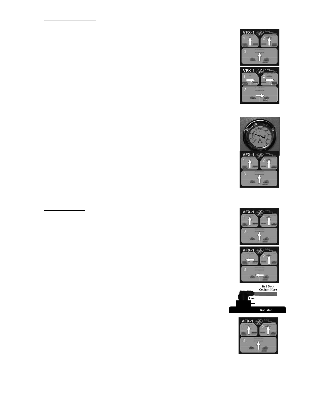
Figure 1
Figure
4
Figure 2
Figure
3
Figure 1
Figure 2
Figure
3
Figure
4
DISCONNECTING
(YELLOW)
To minimize spillage from disconnecting the unit from the vehicle the coolant level
needs to be lowered again using the LOWER LEVEL
(YELLOW)
procedures:
1) Verify adequate capacity for used fluid in used fluid sight gauge. Refer to
EMPTY USED coolant section to empty used coolant tank.
2) Verify that all VFX 1 Control panel valves are in the neutral position, (Fig 1)
and flow control valves at hose ends are off.
3) Turn AIR CONTROL valve (#1), FUNCTION CONTROL valve (#2)
and FLUID CONTROL valve (#3) to the right, LOWER LEVEL
(YELLOW).
Vacuum will begin to build on the compound gauge.
(Fig 2)
4) Connect vacuum cone with extension tube to BLACK/USED coolant
hose and open BLACK/USED coolant flow control valve at hose end.
5) Lower coolant level below radiator hose disconnection level. When
vacuum reaches 10inHg, coolant level should be below disconnect
level. (Fig 3)
6) Close BLACK/USED coolant flow control valve at hose end.
7) Return all control panel valves to neutral position, (Fig 4) and flow
control valves at hose ends to off.
8) Step adapters and hose adapters can now be removed and system restored to
original configuration.
TOPPING OFF
1) Verify all control panel valves are in neutral position.
(Fig 1) Turn both flow control valves at hose end OFF.
2) Turn AIR CONTROL valve (#1) and FLUID
CONTROL Valve (#3) to the left, TOP OFF
(
GREEN
up, TOP OFF (
), FUNCTION CONTROL valve (#2) straight
GREEN
). (Fig 2)
3) Connect cone assembly to RED/NEW coolant flow control valve. (Fig 3)
4) Place vacuum cone into radiator or Remote Reservoir neck. Slowly open
RED/NEW coolant flow control valve, observing coolant fluid level.
(Fig 3)
5) Close RED/NEW coolant flow control valve when proper coolant level is
reached.
6) Fill overflow tank to proper level following the procedures described in
steps 4 and 5.
7) Return all control panel valves to neutral position. (Fig 4)
8) Replace radiator / remote reservoir, and overflow caps.
14
Page 16

Figure 3
Figure
1
Figu
re 6
Figure
5
Figure 2
Figure
4
Changeover of PRIMARY
The VFX 1 can be used with multiple coolant types by simply switching between the PRIMARY (internal) Fluid Tank
and an ALTERNATE (external) Fluid Tank. The VFX 1 comes with one additional ALTERNATE (external) Fluid
Tank. Additional tanks can be purchased through Symtech Corporation or one of its Distributors. Inquire for a
Distributor location nearest you.
(internal)
Coolant Tank to
ALTERNATE (external)
Coolant Tank
1) Verify that all control panel valves are in neutral position, (Fig 1) and
flow control valves at hose ends are OFF.
2) Connect to clean shop air (70-120psi).
3) Move New ALTERNATE (external) coolant tank next to VFX 1.
Remove Lid from ALTERNATE (external) Tank container.
4) Pull out the ALTERNATE (external) Tank connection hose from VFX
1 and connect coupler to ALTERNATE (external) Tank lid. Verify diptube is open to atmosphere. (Fig 2)
5) Turn Coolant Tank select valve to ALTERNATE (external) Coolant Tank.
6) Turn AIR CONTROL valve (#1) and FLUID CONTROL valve (#3) to the
left, TOP OFF (
GREEN
). (Fig 3)
7) Connect cone assembly to RED/NEW coolant flow control valve
at hose end.
8) Place cone into fill spout of PRIMARY (internal)coolant fluid Tank,
SLOWLY open RED/NEW coolant flow control valve at hose end.
9) Close RED/NEW coolant flow control valve at hose end when
all coolant has been purged from unit.
10) Return all control panel valves to neutral position. (Fig 4)
11) Replace lid on ALTERNATE (external) coolant tank. Connect
ALTERNATE (external) tank hose coupling.
12) Turn AIR CONTROL valve (#1) and FLUID CONTROL valve (#3) to the left,
TOP OFF (
GREEN
). (Fig 5)
13) Place cone assembly still connected to RED/NEW coolant flow control valve
into tool storage compartment at front of machine, or waist fluid container.
SLOWLY Open RED/NEW coolant flow control valve at hose end.
14) Close RED/NEW coolant flow control valve at hose end when air has
been purged from line or a steady stream of coolant from ALTERNATE
(external) tank flows from unit.
15) Return all control panel valves to neutral position. ( Fig 6)
16) Unit is now ready to perform coolant system service with Exterior Tank
coolant.
15
Page 17

Changeover of ALTERNATE (external) Coolant Tank to PRIMARY (internal) Coolant Tank
Figure 3
Figure 2
Figure
1
Figure
5
Figure
4
1) Verify all control panel valves are in neutral position, (Fig 1) and
flow control valves at hose ends are OFF.
2) Connect to clean shop air (70-120psi).
3) Romove lid from ALTERNATE (external) coolant tank and connect to
ALTERNATE (external) coolant tank hose.
4) Turn Coolant select valve to ALTERNATE (external) Coolant Tank.
5) Turn AIR CONTROL valve (#1) and FLUID CONTROL valve
(#3) to the left, TOP OFF (
GREEN
). (Fig 2)
6) Connect vacuum cone assembly to RED/NEW coolant flow
control valve at hose end.
7) Place vacuum cone into ALTERNATE (external) coolant fluid
tank, SLOWLY open RED/NEW coolant flow control valve at
hose end.
8) Close RED/NEW coolant flow control valve at hose end when all coolant has
been purged from unit.
9) Return all control panel valves to neutral position. (Fig 3)
10) Replace lid on ALTERNATE (external) Tank and store for future use.
11) Turn AIR CONTROL valve (#1) and FLUID CONTROL valve (#3) to the left,
TOP OFF (
GREEN
). (Fig 4)
12) Place cone assembly still connected to RED/NEW coolant flow control valve
into tool storage compartment at front of machine, or waist fluid container.
SLOWLY Open RED/NEW coolant flow control valve at hose end.
13) Close RED/NEW coolant flow control valve at hose end when air has been
purged from line or a steady stream of coolant from PRIMARY (internal) coolant
tank flows from unit.
14) Return all control panel valves to neutral position. (Fig 5)
15) Unit is now ready to perform coolant system service with PRIMARY (internal)
Tank coolant.
16
Page 18

Figure
1
Figure
2
Figure
3
Figure
4
Figure
1
Figure
2
Figure
3
Figure
4
Empty Used Coolant
1) Verify all control panel valves are in neutral position, and flow control
valves at hose ends are OFF.
2) Connect to clean shop air supply (70-120psi).
3) Turn AIR CONTROL valve (#1) and FUNCTION CONTROL valve (#2) to
the left EMPTY USED (
right, EMPTY USED (
PURPLE
PURPLE
) and FLUID CONTROL valve (#3) to the
).
4) Connect cone assembly to BLACK/USED coolant flow control valve at hose
end. (Fig 3)
5) Secure cone assembly into used coolant storage vessel. SLOWLY open
BLACK/USED coolant flow control valve.
Note: The unit uses regulated air pressure (up to 30psi) to empty
the used coolant from the unit. Once the used fluid has been
expelled, the air pressure will cause the BLACK/USED
coolant hose to “jump” or “jerk. Properly secure the hose to
prevent spills.
6) Close BLACK/USED coolant flow control valve at hose end when all used
coolant drains from unit.
7) Return all control panel valves to neutral position. (Fig 4)
Empty Tool Storage compartment Waste Fluid Reservoir
1) Connect clean shop air supply (70-120psi).
2) Turn
AIR CONTROL
FLUID CONTROL
valve (#1), FUNCTION CONTROL valve (#2), and
Valve (#3) to the right LOWER LEVEL (
YELLOW
Vacuum will begin to build on the compound gauge. (Fig 1)
3) Connect extraction cone to BLACK/USED coolant flow control valve.
(Fig 2)
4) Insert extraction cone over tool storage compartment waste fluid
reservoir tube and remove all used coolant from reservoir. (Fig 3)
5) Open BLACK/USED coolant flow control valve at hose end.
6) When used coolant flow ceases, close used coolant flow control valve at hose
end.
7) Return all control panel valves to correct neutral position, (Fig 4) and
flow control valves at hose ends to off.
17
).
Page 19

Troubleshooting
PROBLEM SOLUTION
Vacuum speed or level is reduced - Inadequate air supply. Must maintain 70psi
minimum throughout service.
- Air powered vacuum venturi has become clogged
with debris from dirty air supply.
Please contact Symtech for service procedures.
- Leak in the unit. Please contact Symtech
Corporation for service procedures.
Removal of coolant stops prematurely (before all
removable coolant is removed)
Vacuum level of at least 20inHg is obtained but no
coolant is removed
Used coolant tank sight gauge is too dirty to view
level
Used coolant is leaking from bottom of unit
New coolant did not or can not adequately refill
vehicle
- Cone has become dislodged or unseated from
radiator or Remote Reservoir tank neck. Check that
cone is properly seated and vacuum level of at least
20inHg can be obtained
- Cone may be “bottomed out” on shallow radiator or
Remote Reservoir tank neck preventing coolant
flow. Cone may need to be trimmed back to
prevent “bottoming out”
- Sight gauge can be restored to new by emptying
used coolant tank and replacing sight gauge with new
17.5” X 3/8 O.D. length of new vinyl tube. Available
at Symtech.
- Used coolant tank has been over-filled and used
coolant is escaping through relief valve of tank.
- Possible leak inside unit – contact Symtech
Corporation for service procedures
- New coolant tank level or supply is empty or
coupler disconnected. Check level and replenish if
necessary. Check coupler for proper connection to
new coolant tank.
Coolant exchange in FLUSH mode does not occur.
- Recheck all connections, control panel valve
positions, and flow control valve positions and
retry. See pages 11 and 12
- Reverse RED/NEW and BLACK/USED hose
connections and retry. See pages 11 and 12
- Start vehicle allowing it to reach normal operating
temperature and retry. See pages 11 and 12
For more information and Frequently Asked Questions, and to watch demo videos, please
go to…. www.symtechcorp.net
18
Page 20

Safety by Design
WARRANTY STATEMENT
All Symtech Corporation Coolant Service products are warranted to be free from defects in material and
workmanship under normal use and service for a period of one year from time of purchase. Adapters and fittings
are warranted for a period of ninety (90) days. Exception to this policy will be individually evaluated and must be
approved by Symtech Corporate. The sole obligation under this warranty shall be to repair, or replace any defective
product, or components thereof which upon examination is/are deemed to the manufacturers satisfaction to be
defective.
Warranty shall not apply to any product which has been subject to misuse or negligence. Manufacturer shall not be
responsible for any special or consequential damages and the warranty as set forth is in lieu of all other warranties,
either expressed or implied. However, the manufacturer makes no warranty of merchantability in respect to any
products for any purpose other than that stated in literature and any applicable manufacturers shop or service
manuals referred to therein, including subsequent service bulletins.
Proof of purchase MUST accompany all warranty claims.
SERVICE STATEMENT / COMMITMENT
Symtech Corporation prides itself on personal, in-depth, service communication, if you encounter difficulties in the
operation, understanding of procedures or have general service questions we urge you to contact us at;
1-888-884-8182
This is not a thoughtless statement as our reputation is directly dependent upon your overall satisfaction.
It is our commitment to you that your satisfaction and favorable equipment experience is foremost to us. We will
endeavor to meet the high standard that you expect and deserve.
TECHNICAL SUPPORT
1-888-884-8182
8am to 5pm Central Standard Time.
19
 Loading...