

Page 1

ELECTRONIC
HEADLAMP ALIGNMENT
SYSTEM
ASSEMBLY
CALIBRATION
OPERATION
REV 9, 26, 2011
524 S. E. Transport Drive
Lee’s Summit, Missouri 64081
888-884-8182
816-525-9263 FAX: 816-525-9283
www.symtechcorp.net
Page 2

2
Page 3

INDEX
1. GENERAL Pg. 5
1.1 GENERAL ASSEMBLY INSTRUCTIONS
1.2 BASE / MAST CALIBRATION
1.3 MIRROR CALIBRATION PROCEDURE
2. SYSTEM COMPONENTS Pg. 65
2.1 CONTROL PANEL
2.1.1 ADJUSTMENT SELECTION BUTTON
2.1.2 ON/SELECT BUTTON
2.1.2.1 POSITION CHECK/BATTERY CHARGER LEVEL
2.1.2.2 HEADLAMP BEAM SELECTION
2.1.3 INTENSITY CHECK + BATTERY CHARGER METER
2.1.3.1 READING INTENSITY AND BATTERY CHARGER METERVEHICLE ALIGNMENT MIRROR
2.1.4 LAMP POSITION INDICATOR ARROWS
2.1.5 BATTERY CHARGER SOCKET
2.2 ALIGNMENT HEAD
2.3 MAST
2.4 WHEEL BASE
2.5 FLOOR RAIL
2.6 VEHICLE POSITIONING MIRROR
2.7 ALIGNMENT HEAD & MAST
3. OPERATION Pg. 8
3.1 ALIGNMENT BAY(s) PREPARATION
3.2 FLOOR SLOPE MEASUREMENT
3.3 MULTIPLE BAY ALIGNMENTS & WHEEL POSITION RECORDING
3.4 VEHICLE ALIGNMENT / POSITION TO ALIGNMENT HEAD
3.5 HEADLAMP ALIGNMENT
3.6 MAINTAINING POWER
3.7 OPERATING PROCEDURE, STEP BY STEP
4. LASER CALIBRATION PROCEDURES PG. 12
4.1 LASER CALIBRATION PROCEDURE ASSURANCE
FREQUENTLY ASKED QUESTIONS Pg. 12
WARRANTY Pg. 14
CUSTOMER SERVICE
2.1.5.1 BATTERY PACK
2.2.1 OPTICAL HEAD
2.2.2 POSITION SENSORS
2.2.3 LEVEL VIALS
2.3.1 GLIDE PLATE
2.4.1 FLOOR SLOPE ADJUSTMENT WHEEL ASSEMBLY
2.4.2 UNIT LEVELING ADJUSTMENT WHEEL ASSEMBLY
2.4.3 WHEELS TO WHEELBASE MOUNTING
2.5.1 FLOOR RAIL OPERATION
3.2.1 POSITIONG THE ALIGNMENT HEAD TO THE FLOOR SLOPE
LASER BATTERY REPLACEMENT
3.4.1 ALIGNING THE ALIGNMENT HEAD TO VEHICLE
3.4.2 SELECTING THE POSITION CHECK
3.4.3 POSITIONG THE ALIGNMENT HEAD BEFORE VEHICLE
3.5.1 CHOOSING HEADLAMP BEAM TYPE
3.5.2 ALIGING THE HEADLAMP
3.5.2.1 USING THE INDICATOR ARROWS
3.6.2 CHECKING BATTERY CHARGE STATUS
3.7.1 LOWBEAM, HIGH BEAM, & FOG/DRIVING PROCEDURE
3.7.2 LOW BEAM, VOL & VOR ALIGNMENT PROCEDURE
888-884-8182
3
Page 4
1.0 GENERAL ASSEMBLY & CALIBRATION
(1)
1.0 GENERAL ASSEMBLY & CALIBRATION
6
7
5
9
8
Tension
Adjustment Screws
2
1
4
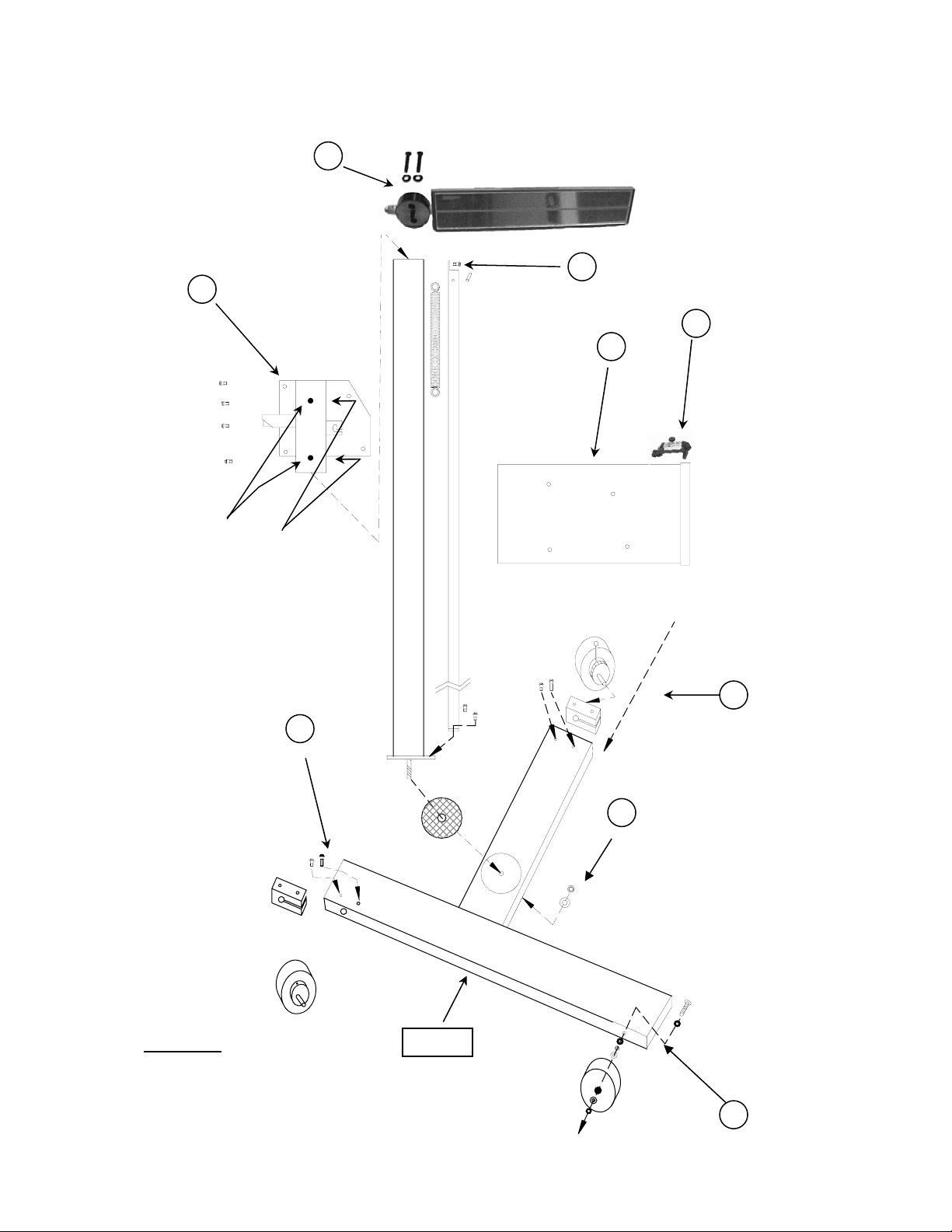
Parts List
Accessory Box
(1) AC Battery Charger
(1) Front Eccentric Axle assembly w/ wheel and handle
(1) Rear Eccentric axle assembly w/ wheel and handle
(1) Wheel w/ straight axle bolt assembly
(1) Mirror assembly
(2) 1/4-20 x 1 1/2 Allen head cap screws
(2) 1/4 steel washers
(1) Laser assembly
Glide Plate Assembly
Front
3
4
Page 5
1.1 GENERAL ASSEMBLY INSTRUCTIONS
Step 1 Insert Front Eccentric Axle assembly (eccentric without scale). Rotate eccentric axle until small scribe mark aligns with indicator arrow on base.
Tighten mounting screws.
Step 2. Insert Floor Slope Eccentric Axle assembly (attached indicator scale & handle). Tighten mounting screws.
Step 3. Place flat washer on 5/16”-18 x 2.5” bolt and push bolt through hole inside of base. Secure bolt in place using one 5/16” steel flat washer and non-
locking nut. Tighten until bolt is secure. Place one thin 5/16” nylon washer on bolt, followed by wheel, additional nylon washer and locking 5/16”
nut. Tighten locking nut until wheel is snug but spins freely.
Step 4. Lay the wheelbase flat on floor. Place the nylon thrust bushing over the hole in the center of the wheelbase. Holding the mast upright, place the stud on
the bottom of the mast through the bushing and into the hole in the center of the wheelbase. Tilt the wheel-base and mast together until you can access
the large hole on the bottom of the wheelbase. Place the provided1/2” flat washer and self-locking nut on the stud, and tighten to zero tolerance.
Loosen 1/16 turn at a time until the mast rotates smoothly with slight resistance.
Step 5. Remove attachment screw at top of mast spri ng cover.
Step 6. Slide Glide Plate over end of mast, between mast and mast spring cover, ensuring that handle is pointed away from spring cover. Slide glide plate
down over mast until the spring hook of the glide plate is even with the bottom of the spring inside of the mast spring cover. Place bottom of spring
into spring hook, and reattach screw at top of mast spring cover.
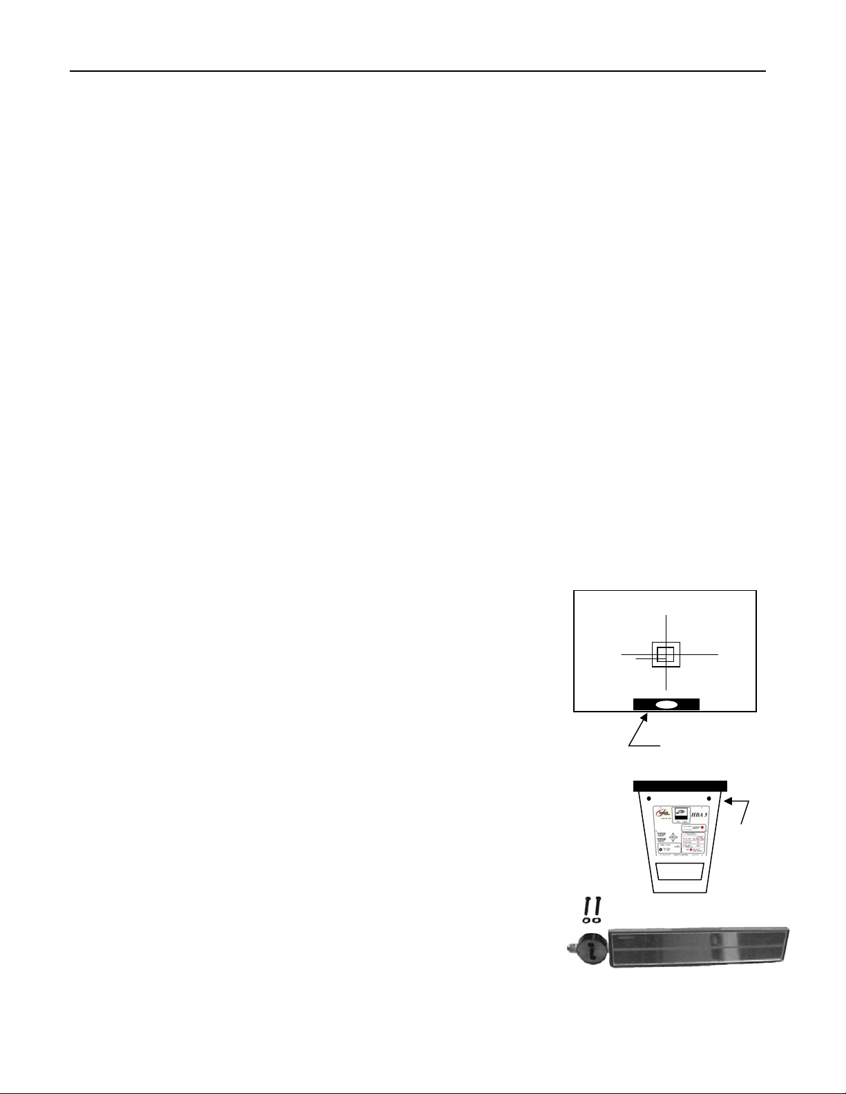
Step 7. Place Mirror Assembly on top of mast, and attach using two ¼”-20 x 1 ½” Allen head cap screws with 1/4” washers, insuring that mirror extends out
Step 8. Mount the HBA5 Head to the glide plate with four ¼”-20 button head cap screws.
Step 9: Remove viewing window (window is attached with tape during shipment) and packet of attachm e nt scr e ws. Attach battery to terminal and adhere to
Step 10. Place Laser on top of HBA5, unit assembly is complete. NOTE: The laser is to be removed from the head when floor slope calibration procedure is
Step 11. Battery must be initially charged for 12 hours prior to first use for optimum performance.
1.2 BASE / MAST CALIBRATION
Step 1: Verify that scribe mark on eccentric axel is aligned with arrow on base. Calibration Complete
IF NOT
Step 2: Locate a level surface area and place HBA 5 in this area.
Step 3: Lower HBA 5 alignment head to its lowest point.
Step 4: Loosen bolts on front eccentric wheel (1).
Step 5. While viewing level vial, located on the aiming screen, rotate the front eccentric wheel until level vial is centered.
Step 6: Tighten bolts on front eccentric wheel, recheck level vial for center. Calibration Complete.
NOTE: Four (4) tension adjustment set screws are located on the glide plate, two (2) are visible on the outside of the glide plate and two (2) are
located on the side that is covered by the spring cover. If glide plate becomes loose, or is overly tight during assembly, these tension
screws can be loosened/tightened for optimum operation and smoothness.
NOTE: Lightly lubricate mast with light-weight oil for smooth movement of glide plate. DO NOT lubricate side of mast that has the brake
mechanism, if oil is place on this side of mast, brake could loose friction properties during use.
on the same side of the mast as the glide plate. Tighten the locking nut until the mirror is held tight, but is allowed to turn with slight resistance.
side of head with supplied Felcro fastener. Replace window and attach with supplied screws.
NOT being performed.
LEVEL VIAL
1..3 MIRROR CALIBRATION PROCEDURE
Step 1: Standing at the rear of the alignment head (opposite the lens,) note the black calibration points on top
Step 2: Turn mirror down until the mirror’s line and the calibration points on the alignment head can be clearly viewed
Step 3: Line up the calibration points, and the mirror line
Step 4: If the mirror line and the calibration points are not parallel, slightly loosen the mirror mount
Step 5: While viewing the calibration points through the mirror, push or pull the mirror until the line
Step 6: Tighten the mirror mount bolts, holding the mirror firmly in place.
Step 7: Re-check the mirror and alignment head calibration points to ensure they are both parallel.
at front of the alignment head.
in mirror.
bolts on the top of the mast.
in the mirror is parallel with the points on the alignment head.
5
Calibration
Points
Page 6

2.0 SYSTEM COMPONENTS
2.1 CONTROL PANEL
The CONTROL PANEL consists of FIVE areas of interest.
1. ADJUST SELECTION MODE BUTTON
2. ON/SELECT BUTTON
3. INTENSITY CHECK + BATTERY CHARGE METER
4. LAMP POSITION INDICATOR ARROWS
5. BATTERY CHARGER SOCKET
2.1.1 ADJUSTMENT SELECTION BUTTON
When a beam type is selected by pushing the ON/SELECT button the Audit
Adjustment LED will turn on indicating that the aimer is in Audit adjustment mode.
This allows the operator to use the aimer to audit and adjust a vehicle’s headlamp to an
acceptable window of ± 4 Inches horizontally and vertically. Pressing the adjust
selection button switches the operating “Mode” of the aimer to Fine Adjustment so that
the HBA 5 can now be used to Adjust a vehicle’s headlamps to a tighter tolerance of ± 1
inch. The aimer automatically defaults to the audit mode when power is turned on,
indicated by its LED.
2.1.2 ON/SELECT BUTTON
The selection area is used by the operator to select between four options,
“Position Check / Battery Charge Level”
“Low beam”
“High beam”
“Fog & Driving Lamp”
2.1.2.1 POSITION CHECK/BATTERY CHARGE LEVEL
Position Check + Battery Charge Level, performs two functions. The battery charge
can be read in this mode and also the Position Check function is activated for positioning
the HBA 5 in front of the headlamp.
This mode is the default and will always be activated when the HBA 5 is turned on.
2.1.2.2 HEADLAMP BEAM SELECTION
The beam options allow the operator to choose between the three basic headlamp types,
Low Beam, High Beam and Fog/Driving Lamp. Pressing the “ON/SELECT” button will
move through the selections, lighting the LED next to each option.
NOTE: When Low Beam is selected, three low beam type patterns are allowable on US driven vehicles:
SAE: Aligned by Electronic Placement
VOL: Align by Visual Placement or Align on High Beam Pattern
VOR: Align by Visual Placement or Align on High Beam Pattern
NOTE: VOL and VOR patterns must be visually aligned by looking through the viewing
window and adjusting the headlamp to the position as depicted by pictorials. OR,
may be aligned electronically by aligning lamp on HIGH BEAM pattern
2.1.3 INTENSITY CHECK + BATTERY CHARGE METER
The Intensity & battery charge meter functions as a dual meter to display the charge level of the battery and a
determination of the maximum intensity of the headlamp.
2.1.3.1 READING THE INTENSITY AND BATTERY CHARGE METER
The meter is divided into two gauges serving three scales.
The intensity meter has two scales. The bottom scale is in use when the intensity lays within 0 - 25 Kilo
candela (0 - 25000 candela.) When the intensity exceeds 25 Kcd, the meter switches automatically to the top
scale of 0 - 125 Kcd (0 - 125000 candela.) At the bottom of the meter are two yellow L ED lights that light up
when that particular scale is in use.
The bottom gauge serves as an indicator of battery charge when in the position check mode.
4
5
3
1
2
2.1.4 LAMP POSITION INDICATOR ARROWS
The position indicator serves three purposes:
1 When positioning the alignment head, the arrows are used to guide the operator in positioning the HBA 5
with the vehicle’s headlamp.
2 When aiming the headlamp, the arrows are used to inform the operator which direction to adjust the
headlamp when adjusting to zero.
6
Page 7

3 When auditing the headlamp, the arrows indicate if the lamp is within or out of allowable limits of +/- 4 inches.
2.1.5 BATTERY CHARGER SOCKET
The HBA 5 is powered by an internal battery supply that will provide a sufficient amount of power
during working hours. An 110V ac power supply adapter is provided with the system for charging. A
red LED light labeled “Charge” lights up to inform the operator that the battery is receiving power and
is charging.
2.1.5.1 BATTERY PACK
The HBA 5 internal battery is located on the inside of the alignment head. During initial assembly, battery pack must be installed per STEP 9, Assembly
Instructions. The battery pack is detachable and can be removed if determined that it can no longer be rechar ged. Only certified battery packs as
determined by SYMTECH Corporation can be substituted for the original, any unauthorized replacement risks voiding all warranties
2.2 ALIGNMENT HEAD
2.2.1 OPTICAL LENS
The lens on the HBA 5’s alignment head is an impact resistant Fresnel lens designed
specifically to converge the light emitted from the headlamp onto the internal screen. The
pattern of light as seen on the screen is representative of the lamp pattern, as it would appear on
an alignment screen at 25 feet away in a laboratory situation.
2.2.2 POSITION SENSORS
The four position sensors are located on the front of the lens assembly, and are
used to centrally locate the headlamp in front of the HBA5. These sensors send a
signal, which is seen on the lamp position indicator arrows while in the position
check mode.
2.2.3 LEVEL VIALS
The level vials (2) are used as a field calibration reference only, and should not be tampered
with. They are located inside the optical block. The level vial located at the bottom of the aim
screen is used in conjunction with the front eccentric axle to adjust the level from left to right.
The level vial located at top of the head, closest to the viewing window, is used in conjunction
with the rear eccentric axle for field laser calibration and verification.
2.3 MAST
The Mast is used to hold the HBA5 head and mirror assembly. It is attached to the base using a 1/2” diameter stud bolted through
the base, with the unique ability to rotate to allow for minor adjustments to alignment without the need to move the entire HBA5
machine.
2.3.1 GLIDE PLATE
The glide plate handle is used to position the alignment head up and down during
the position check procedure.
Tension adjustment screws are located on the glide plate to loosen / tighten
tension of glide plate
2.4 WHEEL BASE
The wheel-base is used to easily move the HBA5 in front of the vehicle while adjusting or checking
headlamp adjustment. It is designed with both a front and rear eccentric axle for easy adjustment while
leveling the unit. The front axle is adjusted once to level the front of the base, and the rear axle with
the attached scale is used to adjust the HBA5 to the slope of the floor in the bay where headlamp
adjustments are done.
2.4.1 FLOOR SLOPE ADJUSTMENT WHEEL ASSEMBLY
The wheel-base contains 3 wheels. The rear wheel is eccentric, and is used in conjunction with the laser
to match the alignment head with the slope of the floor. The adjustable rear wheel operates by way of a
turning lever, and numeric scale that is used by the operator to measure and
record the floor’s slope.
Make sure to loosen the attachment screws for the axle block before
attempting to adjust the wheel. Damage will occur if this step is not
accomplished first.
2.4.2 UNIT LEVELING ADJUSTMENT WHEEL ASSEMBLY
The front wheel is also eccentric. This wheel is used to set the overall level of the unit during initial set-up. A small scribe
mark is placed on the eccentric axle during calibration at the factory; align this scribe mark with the indicator arrow on the base
Glide Plate Handle
Tension Screws
7
Fresnel Lens
Position
Sensor
Level Vial
Bubble
Wheel Base
Scale
Mast with
Glide Plate
Page 8

at time of initial setup. Make sure to loosen the attachment screws for the
t
axle block before attempting to adjust the wheel. Damage will occur if
this step is not accomplished first.
2.4.3 WHEELS TO WHEELBASE MOUNTING
There are three wheels on the wheelbase. Two wheels have an axle block that allows them to fit inside the
wheelbase, and be adjusted. Each axle block has two bolts, one for mounting to the wheelbase, and a second for
clamping the wheel axle into the block. The eccentric wheel is installed on the right leg of the wheelbase. The
straight shaft wheel is applied to the left leg of the wheelbase. The slope adjustment wheel is applied to the rear
leg Of the Wheelbase.
2.5 FLOOR RAIL
The floor rails are provided for guiding the horizontal movement of the wheelbase along the floor before the
vehicle. The floor rails assure that the alignment of the wheelbase to the vehicle does not change when moving
from lamp to lamp. The rails are attached together by using 1/4” dowel pins. Permanent attachment can be
accomplished by simply placing a couple of drops of locktite to each dowel pin before mating rails.
2.5.1 FLOOR RAIL OPERATIONS
It is recommended that the floor rail be positioned no further than 20 inches +/- 3 inches from the face of the
headlamp lens, and perpendicular to the centerline of the vehicle. The wheelbase’s two front wheels are placed
in the valley of the rail, and the rear wheel can be adjusted to conform to the floor slope of the work bay.
The floor rail is shipped in two 4-foot lengths. Included with the rails are two 1/4” dowel pins.
To assemble, slide the rail with dowel pins in the end of the rail with the arrow, and over the pins until the
edges are flush. The two pieces should hold each other firmly with no loose movement.
NOTE: If attachment of rail guide to floor is desired it will be necessary to drill holes on each end of
the rail into the working surface to accept anchoring devices.
2.6 VEHICLE POSITIONING MIRROR
The vehicle-positioning mirror is used by the operator as a guide in
positioning
he HBA 5 perpendicular to the vehicle headlamp. The mirror contains a
printed line that runs horizontally in the middle of the glass, which serves as
an eyesight guide in aligning the vehicle.
Tension of rotation of mirror should be snug, but loose enough to allow the
mirror to turn.
Mounting Bolt
Printed Mirror Line
Wheel tightening
Bol
2.7 ALIGNMENT HEAD & MAST
The alignment head is attached to the mast by the glide plate. The head fastens to the glide plate by four 1/4-20 x
1/2 Button Head Cap Screws.
3.0 OPERATING PROCEDURE
3.1 ALIGNMENT PREPARATION
Certain preparations must be made prior to beginning the alignm ent process.
1. The alignment area floor should be clean and clear of any unusual objects that could distort the position of the vehicle or the HBA 5 itself.
2. The vehicle should be free of any ice or mud, in and around, the fenders and headlamps. T he vehicle should not have any suspension problems, bad
shocks, springs, or struts causing the vehicle to sag or dip to any one side.
3. The vehicle’s tires should not be noticeably deflated
4. There should be no unnecessary or heavy loads inside the vehicle except for the driver.
5. The headlamps should be cleaned, including any reflective areas around the lenses. The alignment head lens should also be fr ee of any dirt or dust.
6. The headlamp should be checked for burnouts, or condensation inside the lamp. If condensation is present, replacement of the lamp assembly is
recommended.
7. Before setting floor slope, head should be set level using the level vial mounted on the aim screen. Move HBA5 to a known level surface, and
proceed in leveling the head. Adjust the head level (left to right) by loosening and adjusting front eccentric axle until bubble appears in center of
level vial. Re-tighten axle and confirm level of head. You are now ready to set your floor slope.
3.2 FLOOR SLOPE ALIGNMENT
The floor slope adjustment must be performed to align the alignment head parallel with the slope of the floor. Improper floor slope adjustment
will result in improper headlamp alignment. NOTE: Floor rail must be used during floor slope adjustment IF
headlamp alignment procedure.
3.2.1 POSITIONING THE ALIGNMENT HEAD TO THE FLOOR SLOPE
Glide Plate
floor rail is used during
Alignment
Head
8
Page 9

1. Position HBA 5 in front of vehicle with front wheels in floor rail and approximately one foot outside of vehicle.
2. Lower the alignment head to lowest possible position.
3. Adjust the alignment head until level vial is centered. (This is for a starting position only)
4. Install laser on top of alignment head placing position pin in hole located in center of bezel
5. Turn on the laser.
6. Move to the front wheel area of the vehicle
7. With tape measure, measure from floor to where laser beam intersects measuring device. Note this measurement.
8. Move to rear wheel area of vehicle and measure from floor to laser beam. Note this measurement.
9. Adjust alignment head so that laser beam is the same height at both front and rear wheel positions.
10. This is accomplished by rotating the handle on the base of the rear eccentric wheel
NOTE: When adjusting the rear axle, both measurements at automobile will be effected.
11. When both readings are equal, record position indicated on rear wheel scale, and bay.
NOTE: All floor slope measurements must be made with the HBA 5 front wheels placed on the rail, or alignment will be incorrect.
Laser Battery Replacement
On / Off
Knob
Unscrew back of laser and replace batteries with three (3), LR 44 button batteries.
Reverse process for assembly.
After battery replacement, CALIBRATION MAY BE REQUIRED.
Fixture
Placement
Level Adjuster
Set Screw
LR 44
Batteries
3.3 MULTIPLE BAY ALIGNMENTS & WHEEL POSITION RECORDING
In facilities where multiple bays are utilized for headlamp alignment, it is recommended that the position of the pointer mark on the rear leg of the
wheelbase be recorded after determining the floor slope in each bay that is utilized for headlamp alignment. By recording the position of the scale on the
rear wheel, the operator can pre-set the alignment head to the pre-determined slope of the bay and proceed with alignment without the necessity of
performing the steps of measuring the head to the floor slope.
3.4 VEHICLE ALIGNMENT / POSITION OF ALIGNMENT HEAD
The purpose of vehicle alignment is to position the alignment head perpendicular to the vehicle, and
Centerline
position the alignment head to the center of the lamp being checked.
3.4.1 ALIGNING THE ALIGNMENT HEAD TO THE VEHICLE
Place the alignment head at the center of the vehicle. Turn the mirror until the front of the vehicle can be
viewed in the mirror. With the mirror, locate two common
points at opposite sides of the vehicle such as
strut or shock towers, or corners of the hood. On the mirror, observe the guide line. Rotate the alignment
head until the fixed points are in line with the guide line. Be aware to check the alignment of the head
during the remainder of the process to assure that the head remains in alignment.
Line of sight
3.4.2 SELECTING THE POSITION CHECK
To position the alignment head in front of the headlamp the operator must use the indicator arrows as a guide. Press
the “ON/SELECT” button until the LED next to the option “Position Check + Battery Check lights up. Once this
option is highlighted the indicator arrows can now be used to position the alignment head in front of the headlamp.
9
Page 10

3.4.3 POSITIONING THE ALIGNMENT HEAD BEFORE THE VEHICLE
Move the alignment head in front of the headlamp, and observe the indicator arrows on the control panel. The indicator arrows will inform the operator
which direction to move the alignment head. The alignment head is in position when the green center LED lights up
indicating that it is in position to audit or adjust the headlamp.
NOTE: When positioning the alignment head take caution not to rotate the alignment head out of position as determined by
the mirror.
3.5 HEADLAMP ALIGNMENT
The purpose of headlamp alignment is to align the vehicle headlamp such that the driver of the vehicle has the most effective lighting of the road and its
conditions, while still being safe for both the driver and oncoming traffic.
3.5.1 CHOOSING THE HEADLAMP BEAM TYPE
Before aligning the headlamp the operator must designate which beam type is to be aimed. From the
control panel locate the “ON/SELECT” button. The select button provides a choice between low, high
and fog beam patterns. To choose a beam pattern press the select button until the LED next to the
selected beam pattern lights. To visually aim the VOR and VOL low beam patterns select low beam
and proceed to visually aim the lamp per pictorials. Letters marked on headlamp cover should
properly identify VOL and VOR lamps. NOTE: If attempting to align a composite or sealed beam
lamp with high & low beam within the same housing, align only the low beam. If aligning a 4-lamp
system with high & low beams in separate housings it is necessary to cover the low beam while
aligning the high beam if all four lamps are on at the same time.
H
3.5.2 ALIGNING THE HEADLAMP
V
US Low Beam
Adjusting the headlamp with the HBA 5 can be accomplished in either Audit Adjustment or Fine Adjustment modes with the use of the indicator arrows.
3.5.2.1 USING THE INDICATOR ARROWS
With the alignment head aligned, and beam type selected. The arrow LED’s should be lighting up in one or two directions
revealing which directions to adjust the headlamp. While observing the indicator arrows, adjust the vehicle headlamp until
the arrows red LED’s go off, and the green center LED lights up. This indicates that the headlam p is now pr operly
aligned.
Note: Audit Adjustment mode adjusts lamps to within a window +/- 4 inches from center. Fine Adjustment mode
adjusts lamps to within a +/- 1 inch window.
Note: Observe the intensity meter during adjustment. If meter is rising, adjustment is being performed in the
correct direction.
3.6 MAINTAINING POWER
The HBA 5 is designed to run on an internal battery powered by an AC power supply. The
batteries are charged by way of a battery charger that takes power from an AC power supply
adapter. The adapter is plugged into any 110 VAC wall socket, and into the charge socket
identified on the control panel. The HBA 5 should be charging during non-use hours A red LED
labeled “CHARGE” will light up to indicate that the battery is charging. The internal batteries are
set to provide power for 8 hours if used non-stop, and normal charge tim e is from 12 - 14 hours for
a full battery recharge. HBA 5 is designed with an automatic power off function after
approximately 5 minutes . To bring power back up, all that is needed is to press the “ON /
SELECT” button. It is recommended to plug in the charger and allow a full days charging time
before expected use.
3.6.2 CHECKING THE BATTERY CHARGE STATUS
To check the status of the battery press the “SELECT” button until the red LED
nest to the “Position Check +battery Check” mode is lit. When in the “Position
Check + Battery Check” mode the intensity meter functions as a battery charge
gauge. The bottom scale on the meter is the battery charge scale. If indicator needle
is in the green, the battery is fully charged.
3.7 OPERATING PROCEDURE STEP BY STEP
10
Page 11

3.7.1 LOW BEAM, HIGH BEAM & FOG/DRIVING PROCEDURE
V
V
V
V
The operating flowchart is a step by step procedure to follow when aligning the low beam and high beam lamps
1. Turn laser on. If using adjustment handle scale recording from previous alignment, skip steps 2 & 3.
2. Measure height of laser beam at both front and rear wheels using a tape measure.
3. Adjust rear eccentric wheel so that the height of the laser is equal at both front and rear wheels of vehicle.
5. Place the HBA 5 at center of vehicle. Rotate alignment head perpendicular to vehicle using mounted m i rror and two common points on vehicle.
6. PRESS the ON/SELECT Button. Confirm the LED next to “Position Check” on control panel is lit.
5. Noting the indicator arrows, position the alignment head in front of vehicle headlamp until only center GREEN LED lights up indicating that the
alignment head is perfectly aligned to the headlamp.
8. Audit headlamp by pressing the “ON/SELECT” button until the correct beam type is chosen, and its LED lights up.
9. GREEN light lit denotes that the lamp position is within allowable limits of +/- 4 inches up/down and left/right. RED lights lit denote that the lamp
is outside allowable limits of +/- 4 inches up/down and/or left/right.
9. If GREEN, proceed to step 11
10. If RED, adjust headlamp to GREEN light condition following directions indicated by arrows on control panel.
11. To accept “Headlamp within allowable limits”, proceed to step 14
12. To adjust to “Fine Adjust”, begin headlamp adjustment procedure by pressing the “ADJUST SELECTION” button. Confirm that the LED across
from “FINE ADJUSTMENT” is lit to indicate that it is in FINE ADJUST mode
13. Noting the indicator arrows, adjust headlamp until only center GREEN LED lights up indicating that the headlamp is in perfect alignment.
14. Move to next headlamp position and repeat steps 6 - 13.
15. Press “ON/SELECT” button and confirm that the “Position Check” LED is lit.
16. Repeat 6-14 to adjust HIGH BEAM headlamps
17. Headlamp aiming completed!
In the event that the lamps low beam will not conform to the standards set forth, which can be viewed by the lamps
NOTE:
extreme HIGH/LOW and/or LEFT/RIGHT final position, as depicted below, the following procedure should be followed.
H
H
H
H
US Low Beam
“HIGH”
US Low Beam
“LOW”
US Low Beam
“LEFT”
US Low Beam
“RIGHT”
V
• Switch lamp to HIGH BEAM mode and align lamp according to alignment
procedures specified for the HBA 5 system.
H
• Switch lamp to LOW BEAM mode and visually observe placement of low
beam on rear alignment screen of HBA 5. Pattern should be in a relative
position of alignment and appear as pictorial.
3.7.2 LOW BEAM, VOL & VOR LAMP ALIGNMENT PROCEDURE
The following steps are to be used when aligning the Low beam VOL & VOR lamps.
1. Follow steps 1 - 4 of low beam, high beam, fog / driving lamp opera tion to align, and level the alignment head
2. Use position check to square the alignment head with the lamp.
3. Observe the lamp pattern shown on the aiming screen inside the HBA 5 by peering through the tinted view window on top of the alignment head.
4. Adjust the lamp until the pattern matches that shown in the select window on the control panel for VOL or VOR beams.
5. Move to next lamp and repeat steps 2 - 5. Headlamp aiming completed!
4.0 CALIBRATION PROCEDURES
11
US Low Beam
Correct Pattern
Placement
Page 12

4.2 LASER CALIBRATION PROCEDURE ASSURANCE
”
NOTE: LASER IS CALIBRATED AT FACTORY, CALIBRATION IS REQUIRED ONLY IN THE EVENT OF
TAMPERING WITH ADJUSTMENT SCREW OR ASSURANCE OF LASER ACCURACY.
Step 1: Move the HBA 5 to a level floor surface with a recomm ended six feet (very minimum of four feet) of unobstructed floor in front of the alignment
Step 2: Level the alignment head. Noting the level vial on top of the alignment head, adjust the rear wheel up or down until the vial bubble is perfectly
Step 3: Locate a perfectly level surface, (i.e. frame machine, alignment rack,) if this is not available it will be necessary to create one. This can be achieved
Step 4: Place the board on edge, then place the level on top of the board. Shim one end of the board up until the surface is level according to the level.
Step 5: At front of alignment head measure up from level surface (board) to laser height and record reading from center of laser light.
Step 6: At the furthest point away from the HBA 5 (at least six feet,) again measure up from the level surface (board) and record reading.
Step 7: If the measurements are not equal, adjust the rear height adjustm e nt knob of the laser assembly (Lock Tight has been installed on screw at factory,
head.
centered. The vial is factory calibrated and is permanently affixed.
by using a six-foot or longer board, a steel channel, and a level. Shims may be required to stabilize the leveling surface.
minor pressure should break seal) until laser is viewed at either end of straight edge equally. Laser is now calibrated, installing lock tight or other
adhesive to adjustment screw is recommended.
MOST FREQUENTLY ASKED QUESTIONS ** All referenced pages are from the HBA 5 Instruction Manual
Q: Whom do I call for warranty questions, service and technical assistance?
A: Call Sy mtech Corporation Technical Assistance at 888-884-8182.
Q: How do I turn the HBA 5 OFF?
A: The sy stem will automatically turn off after five minutes of operation.
Q: How do I check calibration of mirror? (Page 3: Section 1.3)
A: Position the optical head approximately middle of mast. Standing behind the machine, turn the mirror down until the front edge of
the optical head can be seen in the mirror. There are two (2) small black calibration marks located near the top front edge of the
optical head. Slightly loosen mirror mount screws on top of the mast. Pivot the mirror until the horizontal line runs directly through
the calibration points on the optical head. Retighten the mirror mount screws.
Q: Are there any headlamps that the system is not able to aim?
A: Sy mtech Corporation makes no claims of any nature that the Sy mtech Corporation Optical alignment Sy stems will align headlamps
that do not conform to the Society of Automotive Engineers (SAE) recommended practices described in standards J599, J600, J1383
and J1735.
In the event that the lamps low beam will not conform to the standards set forth, which can be viewed by the lamps extreme
HIGH/LOW and/or LEFT/RIGHT final position, as depicted below, the following procedure should be followed.
V
V
V
V
H
US Low Beam
“HIGH”
H
US Low Beam
“LOW”
H
US Low Beam
“LEFT
H
US Low Beam
“RIGHT”
V
• Switch lamp to HIGH BEAM mode and align lamp according to alignment
procedures specified for the HBA 5 system.
H
12
US Low Beam
Correct Pattern
Placement
Page 13

• Switch lamp to LOW BEAM mode and visually observe placement of low
beam on rear alignment screen of HBA 5. Pattern should be in a relative
position of alignment and appear as pictorial.
Q: The lights keep blinking on the control panel, what does this mean?
A: Continue blinking of the lights on the control panel indicates either the internal battery requires charging, or that the system is not in
front of a light pattern. It will require twelve (12) hours to full charge battery in system.
Q: How do I measure floor slope? (Page 6~7: Section 3.2)
A: Move the aimer bay to be measured and in front of the vehicle. Move the aimer to approximately one foot outside side of the vehicle
and lower optical head to lowest point. Place laser on optical head and turn laser on. Using a tape measure or yard stick, go to the
front wheel area of the vehicle and measure up from floor to where the laser strikes the tape, note measurement. Go to the rear wheel
area of vehicle and again measure from the floor up to the laser, noting measurement. If measurements differ, rotate the rear floor
slope eccentric on the base until both height measurements are equal. Note the setting of the eccentric wheel tape and record setting
on the floor slope registry.
NOTE: Measurements are required for each bay that the HBA 5 is to be used.
Q: Do I need to always use a track? Does the track need to be attached to the floor? (Page 6: Section 2.5.1)
A: The track is provided to smooth the floor surface and to ensure the system will roll evenly across in front of the vehicle once the
system has been squared to the vehicle. When the system is operated without the track, the system must be squared on each side of
vehicle prior to aligning that sides lamp(s).
NO, the track need not be attached to the floor for proper and accurate alignment.
Q: How do I square the system to the vehicle?
A: While standing behind the system, with system placed in front and centered on vehicle, rotate the mirror down until you can see the
reflection of the front end of the vehicle in mirror. Locate two symmetrical points on the hood or under the hood and pivot the
optical head until the horizontal line on the mirror intersects the two select symmetrical points. System is squared.
Q: What do the boxes mean on the aiming screen?
A: The inside box is equal to four (4) inches Up/Down and Left/Right at twenty-five (25) feet. The larger outside box is equal to eight
(8) inches Up/Down and Left/Right at 25 feet. Check your state regulations for inspection tolerances.
Q: The laser does not light up. How do I change the batteries? (Page 9: Section 4.1)
A: The laser requires three (3) LR44 batteries to operate. To change batteries, remove the On/Off thumb screw and peel back the label
until the set screw is exposed. Using a 5/64
th
Allen wrench loosen the set screw until laser slides out of housing. Unscrew the rear of
laser and remove the old batteries and replace with new. Test laser prior to inserting into holder.
Insert laser into holder, carefull to align On/Off button on laser with thumbsrew hole. Lightly tighten set scew to secure laser in
holder and replace label. Inset On/Off thumb screw and test laser operation.
Calibration of the laser is required any time the laser is removed from the holder. Calibration instructions can be found on
page 9, section 4.1.
Q: There is a level vial attached to the bottom of the aiming screen. What is its purpose? (Page 3: Section 1.3)
A: This vial is used to ensure of vertical straightness of the aiming screen. During assembly of the unit there is an eccentric wheel on the
front of the base that must be correctly positioned to ensure that the mast, optical head and aiming screen are vertical as an assembly.
There is a small scribe mark on the front eccentric wheel that is to be placed directly in line with the indicator arrow on the base.
Should the vial on the aiming screeen be utilized for calibration, the unit must be placed on a true level surface and the front eccentric
rotated until the bubble is centered.
13
Page 14

All Symtech Corporation products are warranted to be free from defects in material and workmanship under
normal user service for a period of one year after the sale of the product.
Exception to this policy will be individually evaluated and must be approved by Symtech Corporation. The sole
obligation under this warranty shall be to repair, or replace any defective product, or parts thereof, which upon
examination are deemed to the seller’s satisfaction to be defective.
The warranty shall not apply to any product that has been subject to misuse, negligence, or accident.. The seller
shall not be responsible for any special or consequential damages and the warranty as set forth is in lieu of all
other warranties, either expressed or implied. However, the seller makes no warranty of merchantability in
respect to any products for any particular purpose other than that stated in literature and any applicable
manufacturers shop or service manuals referred to therein, including any subsequent service bulletins.
The “HBA 5” Optical Headlamp Alignment System has been tested by an AMECA accredited photometric
laboratory and found to comply with the Society of Automotive Engineers (SAE) recommended practices
prescribed in standards j599 and j600.
The seller makes no claims or warranties of any kind that the “HBA 5” Headlamp Alignment System will align
headlamps that do not conform to Society of Automotive Engineers recommended practices described in j599,
j600, j1383, and j1735.
WARRANTY
524 S. E. Transport Drive
Lees Summit, Missouri 34081
888-884-8182
TEL: 816-525-9263 FAX: 816-525-9283
e-mail: Symtech@symtechcorp.net
www.symtechcorp.net
14
 Loading...