

Page 1
Color
VISUAL
HEADLAMP ALIGNMENT
SYSTEM
With:
Visual Assist
Meter
VISUAL ASSIST
HIGH
BEAM
WW
LLLLOOOOWW
BEAM
ASSEMBLY
OPERATION
CALIBRATION
524 S. E. Transport Drive
Lee's Summit, MO 64081
888-884-8182
816-525-9263 FAX: 816-525-9283
www.symtechcorp.net
Page 2

INDEX
1. GENERAL Pg. 3
1.1 CVA 3 EZ ISOColor INTRODUCTION
1.2 SYSTEM COMPONENTS
1.3 LASER WARNING
1.4 VISUAL ASSIST METER & SWITCH
1.5 ISOColor LAMP PATTERN DEFINITION
2. ASSEMBLY Pg. 4
2.1 BASE / WHEEL ATTACHMENT
2.2 MAST / GLIDE PLATE / ROTATIONAL MAST MOUNT
2.3 OPTICAL ALIGNMENT HEAD
2.4 VEHICLE ALIGNMENT MIRROR
2.5 ALIGNMENT MIRROR CALIBRATION
2.6 FLOOR SLOPE LASER
3. OPERATION Pg. 6
3.1 ALIGNMENT BAY(s) PREPARATION
3.2 FLOOR SLOPE MEASUREMENT
3.3 VEHICLE PREPARATION, Prior to Alignment
4. HEADLAMP ALIGNMENT PG. 7
4.1 ALIGNMENT of OPTICAL HEAD TO VEHICLE
4.2 CENTERING on the HEADLAMP
4.3 SELECTING HEADLAMP PATTERN
4.4 ALIGNMENT of HEADLAMP PROCEDURE
5. LASER CALIBRATION / MAINTENANCE Pg. 9
5.1 LASER CALIBRATION
5.2 MAINTENANCE
6. FREQUENTLY ASKED QUESTIONS Pg. 10
WARRANTY Pg. 11
CUSTOMER SERVICE
888-884-8182
Page 3
1. GENERAL
crews
LASER RADIATION
PEAK POWER
WAVELENGTH
400-700
CL
IIIA LASER PRODUCT
g
1.1 INTRODUCTION
The Model CVA 3 EZ ISOColor Visual Headlamp Alignment System is an economical optical alignment tool that
functions under the same principle for accuracy and dependability of an aiming screen, with the added benefit of Color
Defined Lamp Pattern and a Visual Assist meter, without the excessive use of valuable shop space and the confusion
of vertical and horizontal lamp placement. System design and operation has been engineered with the technician in
mind. The CVA 3
facilitates headlamp alignment, with profitability and customer satisfaction the end result.
EZ ISOColor features Color Defined, Lamp Pattern Definition and a Visual Assist meter that
The Model CVA 3
EZ is designed, manufactured and serviced by Symtech Corporation, Olathe, Kansas, the industry
leader in headlamp alignment technology to the service and body repair industries, the architect of the Model ELA 10,
ISOColor , LCA 2
EZ Visual, HBA 5 and PLA 12 Electronic Headlamp Alignment systems and the AIM 200
Headlamp Intensity meter.
We are confident that the CVA 3
EZ ISOColor will provide you with years of exceptional service. Thank you for
selecting a Symtech Safety by Design product to address your headlamp alignment needs.
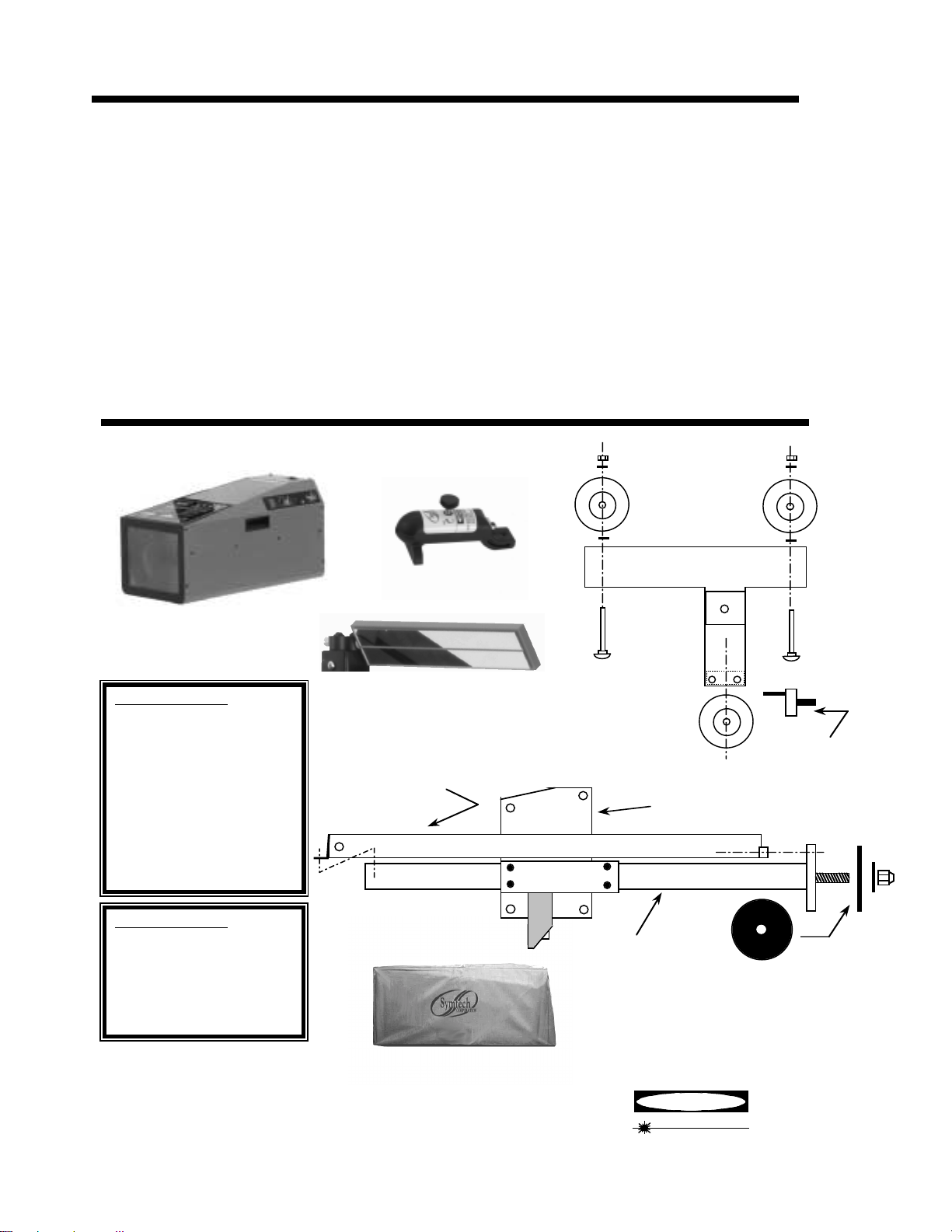
1.2 SYSTEM COMPONENTS
BASE &
WHEELS
FLOOR SLOPE
LASER
OPTICAL HEAD
Small Parts Package
2 Large Nylon Washers
5
2
/16 Nylon Washers
1
2 _ x
2 _ x _ Nylon Spacers
2
/2 Nylon Spacers
5
/16 Self-Locking Nuts
4 _ x 20 Machine Screws
1 _ Self Locking Nut
1 _ Flat Washer
2 _ Black, Flat Washer
2 _ x1.5 Button head Cap
S
VEHICLE ALIGNMENT
MIRROR
COUNTERWEIGHT
SPRING COVER
GLIDE PLATE
FLOOR SLOPE
AXEL
Large Parts Package
2 5/16 x 6 Carriage Bolts
1 Floor Slope Handle
2 Wheels
1 Wheel w/Floor Slope
Eccentric
1 Rotational Mast Bushin
1.3 LASER WARNING
AVOID LOOKING DIRECTLY INTO LASER
LIGHT — POSSIBLE EYE INJURY CAN
OCCUR.
MAST
ROTATIONAL
OPTIONAL
MAST BUSHING
DUST COVER
NOT INCLUDED
DANGER
AVOID DIRECT EYE EXPOSURE
< 5mW
ASS
nm
3
Page 4
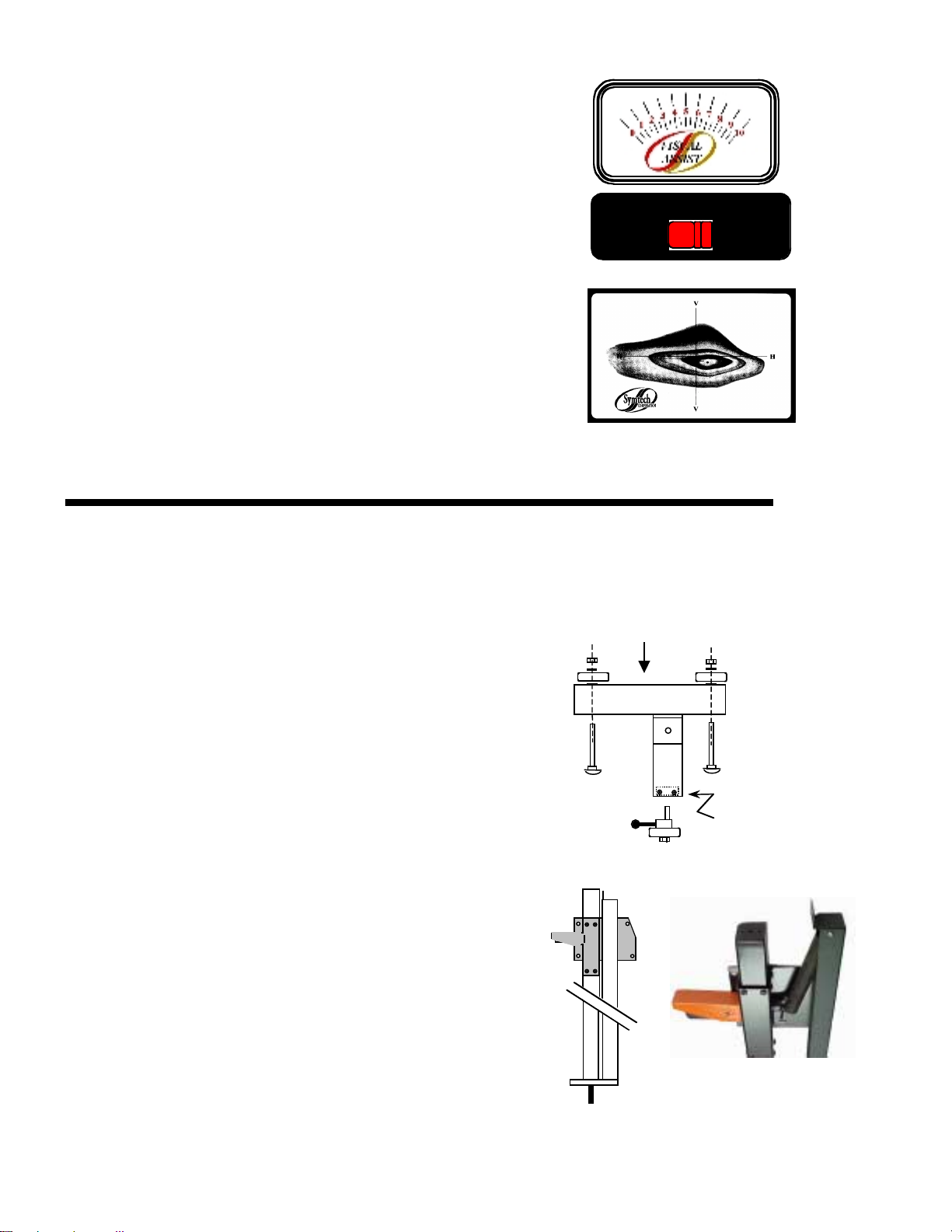
1.4 VISUAL ASSIST METER & SWITCH
The Visual Assist meter is an aide for positioning the headlamp
pattern to its correctly designed position. While visually adjusting
the headlamp into position, the Visual Assist meter will raise in
numeric reading if adjustment is directed in the correct direction.
Adversely, the meter reading will decrease if headlamp is adjusted in
the incorrect direction. When the highest achievable reading is
attained both vertically and horizontally, the headlamp will be
positioned correctly.
The SELECTOR switch moves the Visual Assist meter function
VISUAL ASSIST SSSSEEEELLLLEEEECCCCTTTTOOOORR
HIGH
BEAM
between High and Low Beam patterns. Make sure that the switch is
in the correct location for the beam pattern to be aligned.
1.5 ISOColor LAMP PATTERN DEFINITION
ISOColor technology, unique to Symtech Products, colorizes the
lamp pattern by designating a hue to the intensities of the headlamp.
The headlamp pattern will appear on the screen with the highest
intense portion of pattern being the most inner circle of color, with
varying colors of intensity radiating outward.
2. ASSEMBLY
Inspect all components of the CVA 3EZ system to assure that no damage has occurred during shipment, compare contents
of package with that of the exploded view to make sure that no component has been inadvertently left out of packaging. If
a component is missing, contact our customer service department at 888-884-8182 for an immediate replacement.
RR
WW
LLLLOOOOWW
BEAM
2.1 BASE / WHEEL ATTACHMENT
Place base of system on floor, or table with channel facing
downward.
Insert a 5/16 x 6 carriage bolt into each of the holes noted, making
sure that the square carriage bolt head seats securely into the square
hole placement.
Complete wheel assembly by placing in order a large nylon washer,
wheel, small nylon washer and self-locking 5/16 nut on carriage
bolt.
Tighten self-locking nut snug against wheel, but not so tight as to
hinder free wheel movement.
Insert floor slope eccentric and wheel into mounting block on base
(rear wheel). Tighten friction bolt until floor slope eccentric can be
moved, but not loose enough to move by itself.
2.2 MAST / GLIDE PLATE / ROTATIONAL MAST MOUNT
The Mast, Counterweight Spring Cover and Spring are packaged as
an assembly.
Remove attachment screw at top of mast spring cover.
Slide Glide Plate over end of mast, between mast and mast spring
cover, ensuring that handle is pointed away from spring cover. Slide
glide plate down over mast until the spring hook of the glide plate is
even with the bottom of the spring inside of the mast spring cover.
Place bottom of spring into spring hook, and reattach screw at top of
mast spring cover.
Front of Base
Tighten
this Bolt
Place rotation bearing over mast stud and insert rotational mast stud
into base. Secure mast to base with
1
/2 flat washer and _ selflocking nut. Tighten nut securely then back-off _ turn, or until mast
rotates freely with minor resistance.
4
Page 5
Move glide plate up and down the mast through its full motion, by
y
_
N
depressing handle.
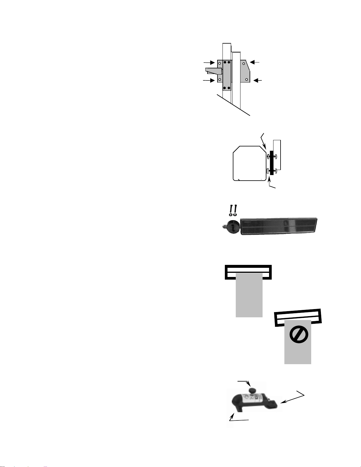
2.3 OPTICAL ALIGNMENT HEAD
Remove optical alignment head from shipping carton.
Inspect for any damage that may have occurred during
shipment i.e. lens, case, etc..
Attach optical alignment head to the mast glide plate by
aligning mounting holes of glide plate with the holes in
the optical head. Insert _ x 20 x _ allen head machine
screws through glide plate, place a _ x _ nylon spacers
on each upper screws, place a _ x
each lower screws, attach optical head and tighten
securely.
1
/2 nylon spacers on
_ x 20 x _
Allen head
Remove protective paper covering from viewing window
on top of optical head.
Move optical head through the full range of movement to
assure of smooth operation.
2.4 VEHICLE ALIGNMENT MIRROR
Vehicle alignment mirror assembly is
in the accessories box.
NOTE: Mount mirror assembly so that unit is
located directly over the optical head.
Insert 2, _ x 20 x 1
Package) into mirror calibration block and attach all
to top of mast.
DO NOT TIGHTEN. Tighten to a tension that
allows for sufficient movement during calibration.
After calibration has been performed tighten
securely.
NOTE: Sighting unit must be calibrated to the optical head prior
1
/2 screws (Small Parts
to alignment of headlamps.
enclosed
2.5 SIGHTING UNIT CALIBRATION
Calibration of sighting unit must be performed prior to alignment of
headlamps.
Raise optical head of CVA 3
of mast.
EZ to the approximate center of travel
Optical
Head
IN
Calibration
Optical
Head
x _ White
ylon Spacers
_ x _ Black
lon Spacers
N
Glide
Plate
Turn the sighting unit until you can see the reflection of the front
edge of the optical head. Line on mirror should line up with the
front edge of the optical head.
If line does not line up with the front edge of optical head, rotate
mirror assembly until line is parallel with front of optical head.
Tighten screws.
OUT of
Calibration
Optical
Head
It is important that periodical checking of calibration of the vehicle
alignment mirror be performed, to assure customer satisfaction.
On / Off
2.6 FLOOR SLOPE LASER
The floor slope laser assembly is factory calibrated, DO
Knob
Level Adjuster
Set Screw
NOT turn the level adjustment set screw which is at the
back of laser assembly.
The laser is used for floor slope measurement only. Remove
laser after floor slope measurements have been recorded
Fixture
Placement Pin
5
Page 6

Remove floor slope laser from packaging and insert front
fixture placement pin into hole on top and at rear of the
optical head, also there is an indentation provided for the
height adjustment screw to rest within.
Activate the laser by turning front knob clockwise
(CAUTION: Excessive turning may damage laser
ON/OFF mechanism) to assure of functionality, turn off
laser. No further adjustment is required.
NOTE: Should calibration of the laser become necessary in
the future, Refer to LASER CALIBRATION .
Calibration, Section 5.1, Pg. 9.
Laser Battery Replacement
Unscrew back of laser and replace batteries with three (3), LR 44
button batteries. Reverse process for assembly.
After battery replacement, CALIBRATION MAY BE REQUIRED.
3. OPERATION PROCEDURES
3.1 PREPARATION, ALIGNMENT BAY(s)
Prior to any headlamp alignment using the CVA 3EZ, the floor slope of the bay, or bays must be determined,
this is done by using the floor slope laser assembly and noting the position of the rear floor slope wheel.
LR44
LR44
If the correct floor slope of the bay is not adjusted prior to any headlamp alignment, the technician will align
the headlamps in a higher, or lower position than what is correct. The CVA 3
EZ must be on the same plain
as the vehicle that is to be aligned, if the vehicle is positioned on a floor that has an upward slope running
from fore to aft of vehicle, then the CVA 3
EZ must be adjusted to have the same slope.
3.2 FLOOR SLOPE MEASUREMENT
Tool Required: Tape Measure or Ruler
Move the CVA 3
front of the vehicle, off to one side. If multiple bays are to be used, procedure for determining floor slope
will need to be performed in each bay and recorded.
MEASURE
Lower the optical head to the bottom of the mast. Adjust optical head by rotating eccentric wheel at rear of
base until level vial registers level. Turn the laser on.
At the center point of the front wheel of the vehicle measure the distance from the floor to the point where the
laser strikes the tape measure, RECORD.
Move to the center point of the rear wheel of vehicle and measure the point where the laser strikes the tape
measure, RECORD.
EZ to the service bay to be used for headlamp alignment and place the CVA 3EZ at the
MEASURE
If the measurements at the front and rear wheels are not equal, the bay has a slope.
Rotate the floor slope handle on rear wheel until equal
measurements are registered at the front and rear wheels.
NOTE: When rotating eccentric axle on CVA 3
EZ, both
measurements will change at front and rear vehicle
6
Page 7
wheels, to achieve equal measurements, more than one
eccentric axle change may be required.
Note the number on the floor slope gauge and record that number along with the bay
designate on floor slope sticker provided. Repeat procedure for other bays and record.
NOTE: After measurements have been taken, remove laser and store in a secure place
3.3 VEHICLE PREPARATION
• Remove ice or mud from under the fenders.
• Set the tire inflation to the values recommended by the manufacturer.
• See that there is no load in the vehicle unusual to normal driving conditions.
• Check vehicle springs for sag or broken leafs.
• Check function of any automatic leveling systems and specific manufacturers instructions
pertaining to vehicle preparation for headlamp alignment.
• Clean lenses, check for bulb burnout, broken mechanical aiming pads, moisture in lens and
proper beam switching.
• Stabilize suspension by rocking vehicle sideways.
4. HEADLAMP ALIGNMENT
4.1 ALIGNMENT OF OPTICAL HEAD TO VEHICLE
Place the CVA 3EZ in front of the first headlamp to be aligned.
Once the CVA 3
be approximately 12 inches (+/- 6 inches) from the face of the
headlamp.
Set the floor slope of the eccentric wheel for the bay in which the
vehicle has been parked.
Rotate the vehicle alignment mirror so that the reflection of the front
of the vehicle can be seen in the mirror. Locate two (2) common
points on or under the hood to align the line in the mirror on.
NOTE: Points can be hood stops, radiator supports, points of
While looking at the mirror, align the line of the sighting unit on the
two common points by rotating the optical head.
The CVA 3
alignment process for each lamp.
4.2 CENTERING on the HEADLAMP
Turn headlamps on. Move optical head up, or down to the center of the
headlamp. Position of center of the headlamp is approximate; a ± 2
allowance is acceptable.
TRICK: A method to determining if position is greater than 2 is by observing
EZ is in place, the lens of the optical head should
fender, etc.
EZ is now aligned with the vehicle. Repeat the
the Visual Assist meter for highest reading while moving CVA
3
EZ left/right and up/down in front of the headlamp to be aligned.
Common Points
MIRROR
4.3 SELECTING HEADLAMP PATTERN
Not all headlamps are created alike and different vehicles
may have different design patterns. To be certain of the
lamp pattern, a designate is located on the lamp at the
bottom of the lens. Patterns of lamps that may be aligned
with the CVA 3
EZ are;
7
Page 8

• SAE HIGH BEAM: All high beam lamps. Highest
H
V
intensity point is centered on the Horizontal /
Vertical axis.
• SAE LOW BEAM: All low beam lamps
manufactured prior to 1999. After 1999, some
vehicles could have headlamp patterns that are
VOR or VOL . The high intensity area is located
in the lower right hand quadrant.
• FOG LAMPS: All fog lamps the top of the high
intensity area is located 4 down and centered on the
Vertical axis.
NOTE: DO NOT use Visual Assist Meter
for alignment assistance for Fog
Lamps
• SAE LOW BEAM
VOR (Visual Optical Right):
Low beam lamps manufactured after 1999, some
vehicles. The high intensity area is located in the
lower right hand quadrant and the beam pattern is
aligned by placing the right upper portion of the
beam pattern on the Horizontal axis.
NOTE: Visual Assist meter can be used when
aligning this lamp type if the lamp is
switched to HIGH beam and aligned as
High beam procedure.
• SAE LOW BEAM
VOL (Visual Optical Left):
Low beam lamps manufactured after 1999, some
vehicles. The high intensity area is located in the
lower right hand quadrant and the beam pattern is
aligned by placing the left upper portion of the beam
pattern on the .4 Degree (2.096 ) Down Horizontal
axis.
NOTE: Visual Assist meter can be used when
aligning this lamp type if the lamp is
switched to HIGH beam and aligned as
High beam procedure.
4.4 ALIGNMENT OF HEADLAMP PROCEDURE
• Locate CVA 3
EZ approximately 12 inches from in
front of the lamp to be aligned.
• Position CVA 3
• Align CVA 3
EZ in front of first lamp to be aligned.
EZ to vehicle by aligning two points
under or above the hood with line in alignment mirror.
• Select headlamp pattern and press Visual Assist
Switch to lamp type, HIGH BEAM or LOW BEAM.
H
H
US Low Beam
V
US Low Beam
VOR
.4 Degree Down
(2.096 Inches)
Headlamp Alignment Procedure
1. Position CVA 3EZ in
Front of first lamp to be
Aligned.
2. Adjust Floor Slope to
Recorded Bay Setting.
3. Square CVA 3 to
Vehicle by Aligning Two
Common Points with
Line in Sighting Mirror.
4. Press Visual Assist
Switch to Lamp Beam
Type.
H
Aim Area
Aim Area
H
High Beam
V
Fog Lamp
V
US Low Beam
VOL
5. Adjust by Centering
the Inner Most
Colored Ring of Lamp
Pattern over circle
designated by selected
Beam Type Arrow and
the Visual Assist
Meter to Highest
Reading.
6. Move CVA 3 to Next
Lamp and Repeat
Steps 3 Through 5.
VISUAL ASSIST SSSSEEEELLLLEEEECCCCTTTTOOOORR
HIGH
BEAM
RR
WW
LLLLOOOOWW
BEAM
8 inches
• While viewing aim screen and Visual Assist meter,
adjust headlamp to position that appears as graphic
illustration of headlamp pattern selected and Visual
Assist meter has reached its highest achievable
H
H
4 inches
reading for that lamp.
NOTE: Graphics on aiming screen denote position
V
of lamp position in inches. Outer box
8
Page 9

denotes 8 inches, inner box denotes 4
inches. Each hash mark denotes 1 inch
increment.
• Repeat steps 2 through 4 for remaining lamps.
6. LASER CALIBRATION / MAINTENANCE
5.1 FLOOR SLOPE LASER CALIBRATION
LASER IS CALIBRATED AT THE FACTORY PRIOR TO SHIPMENT
Calibration Required ONLY if Rear- LASER Adjustment Set Screw has
been tampered with
Tools Required: Elevated Surface (wheel alignment, frame machine)
Level (carpenters level or other means)
6 Straight Edge (board or other means)
5/64 Allen Wrench
Locate an elevated surface and lay the straight edge on surface facing away from
optical head. Check straight edge for level, shim if necessary.
Move CVA 3
optical head so that the mounted laser will shoot down the straight edge.
Adjust the rear floor slope wheel until the level in the optical head is centered. Readjustment of
height of optical block may be necessary.
Adjust the rear height adjustment set screw of the laser assembly (Lock Tight has been installed
on screw at factory, minor pressure should break seal) till laser is viewed at both ends of straight
edge equally.
Laser is now calibrated, installing lock tight or other adhesive to adjustment screw is
recommended.
EZ to end of straight edge, turn on the laser and adjust height of
5.2 MAINTENANCE
The CVA 3EZ will provide years of trouble free operation with minimum maintenance, however, care should
be taken in the day-to-day usage of this service instrument. Following are areas that should be periodically
checked and serviced;
• Check wheel axles nuts for tightness, minor
lubrication is recommended.
• Check the optical head mounting bolts for
tightness and tighten as required.
• Check all other mounting screws, bolts and nuts
for tightness.
• Clean the mast area where the brake rides with a
mild detergent to assure of secure holding.
• Clean the front lens, sighting unit and viewing
window with a mild detergent being careful to
use a non-abrasive soft cloth.
9
Page 10

6. FREQUENTLY ASKED QUESTIONS
Question: Level in optical head is not centered during alignment procedure?
Answer: Level vial is used ONLY when checking the calibration of the floor slope laser.
Question: The high intensity (hot spot) area of the headlamp how is this determine?
Answer: All lamps are legislated to be created equal, but this has proven not to be the case. The CVA 3EZ
ISOColor incorporates color definition technology that defines the high intensity zone for ease of
alignment. The most inner circle of color is the high intensity zone, this area should be centered over
the area that is designated by the arrow of the specific lamp pattern being aligned.
Question: Do I have to check for floor slope every time I perform a headlamp
alignment?
Answer: Floor slope need only be performed one time in each bay that the CVA 3EZ is to be used. When
determining the floor slope, record the reading of the rear eccentric wheel on the sticker provided,
Each time you are in that bay, refer to the sticker and adjust the rear eccentric to that measurement.
Question: I cannot attain equal readings at the front wheel and the rear wheel areas when determining the
floor slope.
Answer: The only time that this can occur is when the shop bay has an abnormally excessive angle of slope.
The most frequent problem with determining floor slope is patience in adjusting until the
measurements are equal. A TRICK to assist in making this measurement is to first measure the height
of the laser at the optical head. Then turn the eccentric wheel until the laser reading matches the
measurement of the optical head at the rear wheel area. Check readings at front and rear wheel areas
and make, if any, minor adjustments to equal measurements. RECORD READING OF ECCENTRIC
WHEEL FOR FUTURE REFERENCE.
Question: What do I use as reference when squaring the CVA 3
again when moving from one lamp to another?
Answer: It is always recommended to check the alignment of the sight unit to the vehicle for every lamp to be
aligned. Some reference points that are prominent on most vehicles are the grill, hood line, radiator
support, hood bumpers and common assembly point bolts. Always pick two points that are of equal
proportion.
Question: Can the Visual Assist meter measure light intensity?
Answer: The Visual Assist meter DOES NOT MEASURE LIGHT INTENSITY . It assists in locating the
highest value reading of that particular lamp. If a light intensity meter is an instrument your facility
would like to procure, SYMTECH offers the AIM 200 , a hand held, self-contained precision
instrument specifically designed for measuring automotive light intensities.
Question: Why does the Visual Assist meter have a higher reading on one side of the car than the other?
Answer: Most vehicles will have lamps of varying intensity and patterns. Just use the meter and adjust to the
highest value reading for that particular lamp.
Question: Can I use the Visual Assist meter to help line up the optical head with the headlamp?
Answer: YES. While observing the meter, roll the CVA 3
the optical head vertically until you achieve the highest metered reading.
Question: How do I change the batteries in the Visual Assist meter?
Answer: The meter does not have batteries, power is provided by the light of the headlamp.
Question: Is there a calibration procedure for the Visual Assist meter?
EZ to the vehicle and do I need to square
EZ back and forth horizontally and raise and lower
Answer: NO calibration of meter is required.
10
Page 11

WARRANTY
S
All Symtech Corporation products are warranted to be free from defects in material and workmanship under
normal user service for a period of one year after the sale of the product. Exception to this policy will be
individually evaluated and must be approved by Symtech Corporate. The sole obligation under this warranty shall
be to repair, or replace any defective products or parts thereof, which upon examination are deemed to the
seller s satisfaction to be defective.
The warranty shall not apply to any product, which has been subject to misuse, negligence, or accident. The
seller shall not be responsible for any special or consequential damages and the warranty as set forth is in lieu
of all other warranties, either expressed or implied. However, the seller makes no warranty of merchantability in
respect to any products for any particular purpose other than that stated in literature and any applicable
manufacturer shop or service manuals referred to therein, including any subsequent service bulletins.
The CVA 3, ISOColor Optical Headlamp Alignment System has been tested by an AMECA accredited
independent laboratory and found to comply with the Society of Automotive Engineers (SAE) recommended
practices prescribed in standards j599, j600, j1383 and j1735.
The seller makes no claims or warranties of any kind that the Symtech Corporation Optical Headlamp
Alignment Systems will align headlamps that do not conform to Society of Automotive Engineers recommended
practices described in j599, j600, j1383, and j1735.
afety by Design
11
 Loading...