

Page 1
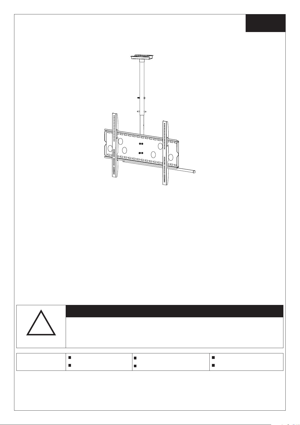
Installation Instruction
English
UNPACKING INSTRUCTIONS
! Careful ly open the ca rton, remo ve content s and lay o ut on c ardbo ard or other p rotectiv e surface to a void damag e.
! Check packag e con ten ts ag ainst th e Suppli ed Parts List in the next p age to assure t hat a ll compo nents we re recei ved
undamag ed. Do not use d amaged or de fective pa rts.
! Careful ly read all in structio ns before at tempt ing i nstal lation.
IMPORTANT SAFETY INFORMATION
Install and operat e this devi ce with car e. P lease rea d this inst ruction befo re beginn ing the ins tallatio n, and carefu lly
follow al l instruct ions conta ined herei n. Use prope r safet y equ ipmen t during ins tallatio n.
Please ca ll a qualifi ed install ation cont ractor for h elp if yo u:
! If you don' t understa nd these dir ectio ns or h ave any d oub ts abou t the safety o f the instal lation.
! If you are un certain ab out the natu re of you r wal l, cons ult a qualif ied instal lation con tractor.
Do not use this product for any p urp ose or in any configura tion not explicitl y speci fied in this inst ruction. We her eby
disclai ms any and all li ability f or inj ury or dam age ar ising fro m incorre ct ass embly, incor rect moun ting, or i ncorr ect use of
this prod uct.
CAUTION!
This TV mount must be securely attached to the ceiling. If the mount is
!
WARNING
not properly installed it may fall, resulting in possible injury and/or
damage.
Tools Required
5/32"(4mm) Drill Bit
Phillips Screwdriver
3/5"(10mm) Masonry Bit
Stud Finder
Wrench or Socket Set
Carpenter's Level
Note: The mounti ng c omponent s and h ardwa re s upplied in thi s package are not designed for insta llati ons to
ceiling s with steel studs. If t he hardwa re you need f or you r install ation is not included , plea se con sult your local
hardwar e store for pr oper mount ing har dware for th e applicat ion.
1
Page 2
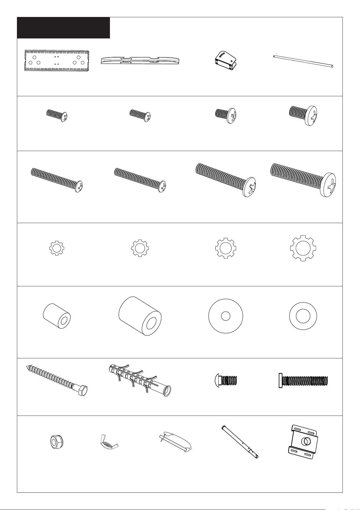
Supplied Par ts List
(1)Wall Plat e-a (1)Co nnection Part-c (1)Lo cking Bar-d(2)Mo nitor Bracket-b
(4)M4 x12 Bolt-e (4)M5 x12 Bolt-f (4)M6 x12 Bolt-g (4)M8 x16 Bolt-h
(4)M4 x30 Bolt-i (4)M5 x30 Bolt-j (4)M6x3 5 Bolt-k (4)M8 x40 Bolt-l
(4)M4 L ock Was her-m (4)M5 L ock Was her-n (4)M6 Loc k Washe r-o (4)M8 L ock Was her-p
(4)M4 /M5 Space-q (4)M6 /M8 Space-r (8)M4/M5 Washer-s (18)M 6/M8 Wa sher-t
(4) -uM8x90 L ag Bolt (4) -vM10x8 0 Concrete Anchor
(5)Nu t-y
(4)Sh ort Bolt-w
(3)Lo ng Bolt-x
(1)Tube Set- B (1)Ce iling Plate-C(1)Se curity Loop-A(2)Bu tterfly Nut-z
2
Page 3
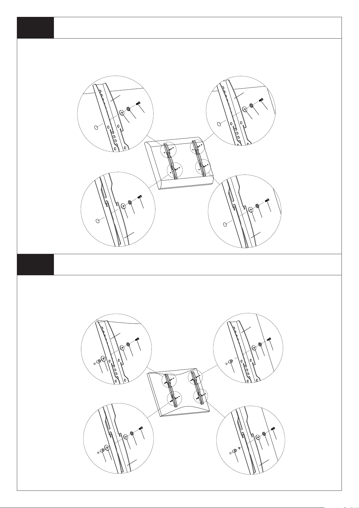
Step 1A
First of all, make sure the d iameter o f the B olt (e,f, g,h) your TV req uires . On ce you have dete rmined th e correct diameter,
please see the re lative diagram as bel ow. You will thread the B olt in to the TV using the correct Lock Washe r(m,n,o, p) and
Was her (s,t) . Please mak e sure the Mon itor Brack ets(b) are v erticall y centered a nd level wit h each other.
Mounting the Monitor Brackets to a TV with Flat Back
M4 Diamet er Bolt
b
s
M5 Diamet er Bolt
s
M6 Diamet er Bolt
b
e
m
Diagram 1 A
M8 Diamet er Bolt
f
n
b
g
o
t
h
p
t
b
Step 1B
First of all, Once you have deter mined the corre ct di ameter,
please see the relative diagram as below. You will threa d the Bolt i nto the TV u sing t he correc t Loc k Washe r(m,n,o, p),
Was her (s,t) and spa cer(q,r) . For t he M4 o r M5 diame ter bolt, you wil l nee d ano ther M4/M5 Washer betwe en th e Monitor
Bracket a nd the Space r. Please mak e sure the Mon itor Br ack ets are v erticall y centered a nd level wit h each other.
make sure the dia met er of t he Bolt(i, j,k,l) your TV re quire s.
Mounting the Monitor Brackets to a TV with Curved Back
M4 Diamet er Bolt
b
m
s
s
q
M5 Diamet er Bolt
i
Diagram 1 B
M6 Diamet er Bolt
b
o
t
r
M8 Diamet er Bolt
k
j
n
s
s
q
b
r
l
p
t
b
3
Page 4
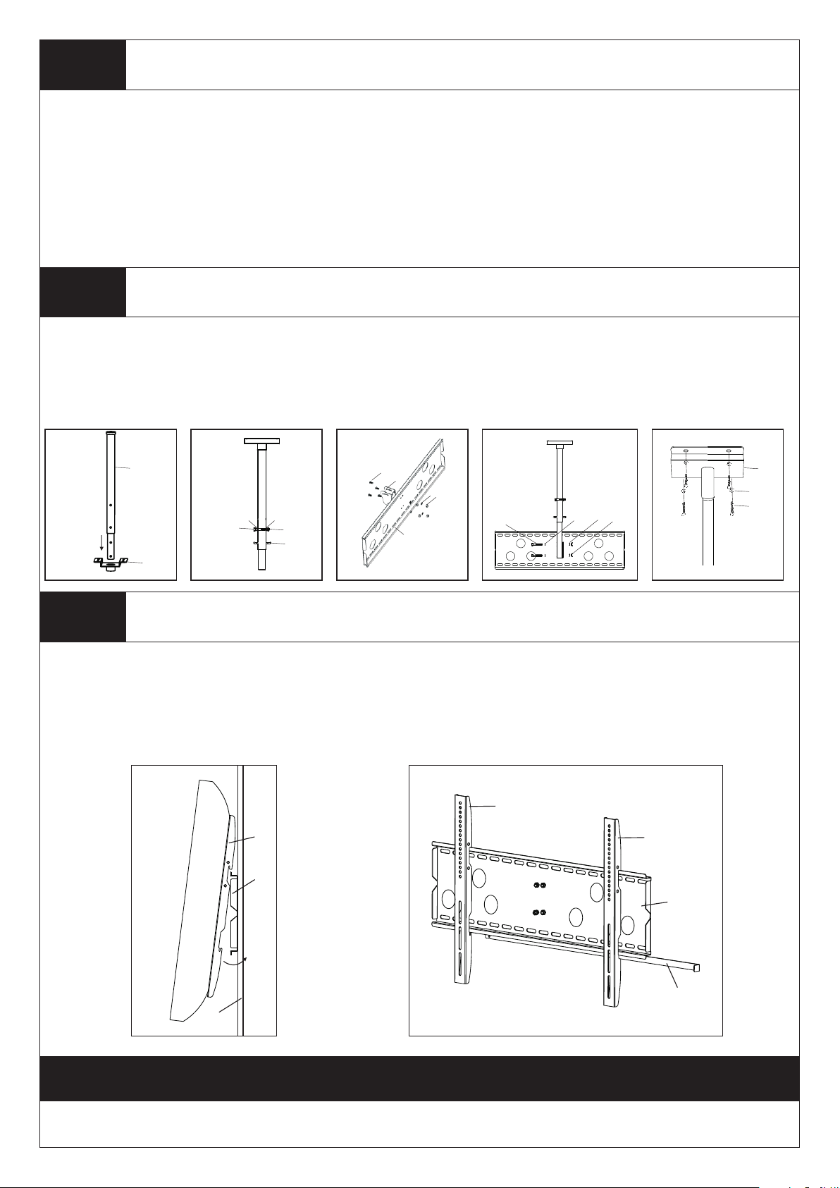
Step 2
Assemble the Ceiling Mount
Step 2A: Fi nd the Tube Set (B) from box a nd pass thro ugh the m idd le hole o f Ceiling Pl ate(C), se e Diagram 2A .
Step 2B: Determin e th e extensi on height you want for t he Tube Set(B) , make sur e two holes of each tube are leveled o ne
by o ne. U se th e Lon g Bol t(x) and H exagon Nut(y) to fix th e top hole and use the Securit y Loo p(A) to fi x the bott om ho le, s ee
Diagram 2 B.
Step 2C : Use 4pcs S hort Bol t(w), 4pcs He xagon Nu t(y) and 4pcs M6/M8 Washer( t) to fix th e connec tion Part(c) on the
Wal l Pla te(a) , see D iagra m 2C.
Step 2D: De termine th e angle you want to t ilt for the Tv and Conn ect the bott om of Tu be Set(B) to t he back plat e of Wall
Plate(a ) using 2pcs L ong Bolt(x ), 2pcs Butt erfly N ut(z) and 4p cs M6/M8 Wa sher(t), s ee Diagram 2 D.
Step 3
Use the Ceiling P late(C) a s a template to mar k 4 hole loc ations on the c eiling. P re-Drill these holes with a 3/ 8
Mounting the Ceiling Plate to the Ceiling
"(10mm)
masonry b it to at le ast 3"(75m m) in dep th. Insert a C oncrete Anc hor(v ) into each of t hese ho les. Make su re the an cho r is
seated co mpletely f lush with the con crete surf ace even if th ere i s a layer of dry wal l or other mat erial in fro nt. At tach the Wa ll
Plate to th e wall using 4 pcs Lag Bolt s(u) and 4pc s M6/M8 Washer(t ), see Diagr am 3.
Diagram 2 D D iagram 3Diagram 2 A Diagra m 2B
C
t
t
x
t
z
u
Step 4
Diagram 2 C
B
t
t
x
C
y
A
w
c
t
y
a
Attaching Monitor to Wall Plate and Insert the Locking Bar
War nin g: Some T Vs may requi re two peopl e to lift! We are no t responsi ble for pers onal injur y or prod uct damage .
First hook th e Monit or Brac kets( b) over the t op of the wal l Plate (a), th en let the bo ttom of the M onito r Brack ets rot ated to
the bot tom of t he Wall Plate. Th is proce ss is sh own in Diagram 4A. I nsert th e Lockin g Bar(d) into th e slots in the b ott om of
the Monit or Br ackets so that is sits behi nd th e bottom tab on the Wal l Pla te. O nce the Locking B ar pa sses out from the othe r
side of wal l plate, a pad lock can be ad ded for addi tional sec urity. Detail s see Diagra m 4B.
Diagram 4 A Diagram 4 B
b
b
b
a
a
d
wall
Thanks for choosing our products, enjoy the using.
4
 Loading...