

Page 1
ASSEMBLY AND INSTALLATION
INSTRUCTIONS
H0195 / H0196
TO AVOID RISK OF ELECTRICAL SHOCK, BE SURE TO SHUT OFF
WARNING:
NOTES: 1. Before installing, consult local electrical codes for wiring and grounding requirements.
2. READ AND SAVE THESE INSTRUCTIONS.
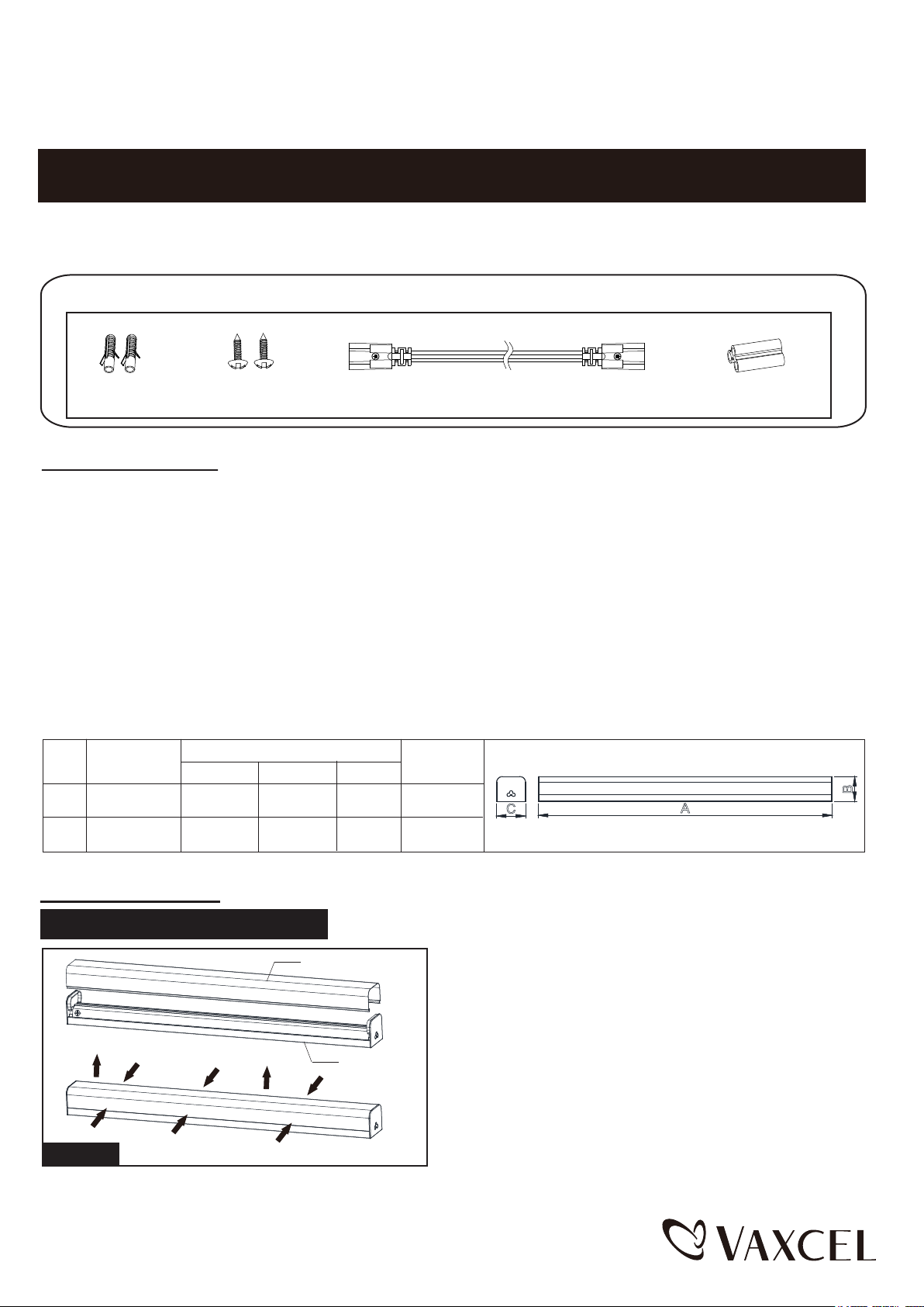
Hardware Package (Included):
POWER BEFORE INSTALLING OR SERVICING THIS FIXTURE.
Anchor (A)
Dry Wall Screw(B)
Linking Cord (C)
Plastic Connector (D)
Important to Know
1. Read all instructions carefully before installation and operation.
2. If you are not familiar with state and local electrical codes, it is recommended that you consult with a qualified electrician.
3. Units can be linked together in series from one power supply. Link up to 24pcs x 24" bar lights (#H0195) together, link
up to 24pcs x 48" bar lights (#H0196) together, or link combination of sizes together.
4. Do not use in wet locations, use indoors only.
5. Non-replaceable LEDs.
6. Caution: LEDs emit bright light. Avoid looking directly into the light source for prolonged periods to avoid eye damage.
7. Not to be used with a dimming circuit or any other electronically controlled switch.
8. Specification:
NO.
1
2
Item #.
H0195
H0196
Dimension(inch)
A
24
48 2
B
2
C
2.5
2.5
Watts
13.5W
30W
B
C
A
Installation Steps
Turn off the power at fuse or circuit box.
Fig.1
PC Diffuser
1. Open the PC diffuser by squeezing and pulling out.
Remove the hardware package which locate in fixture.
Fixture Plate
171207
Page 2
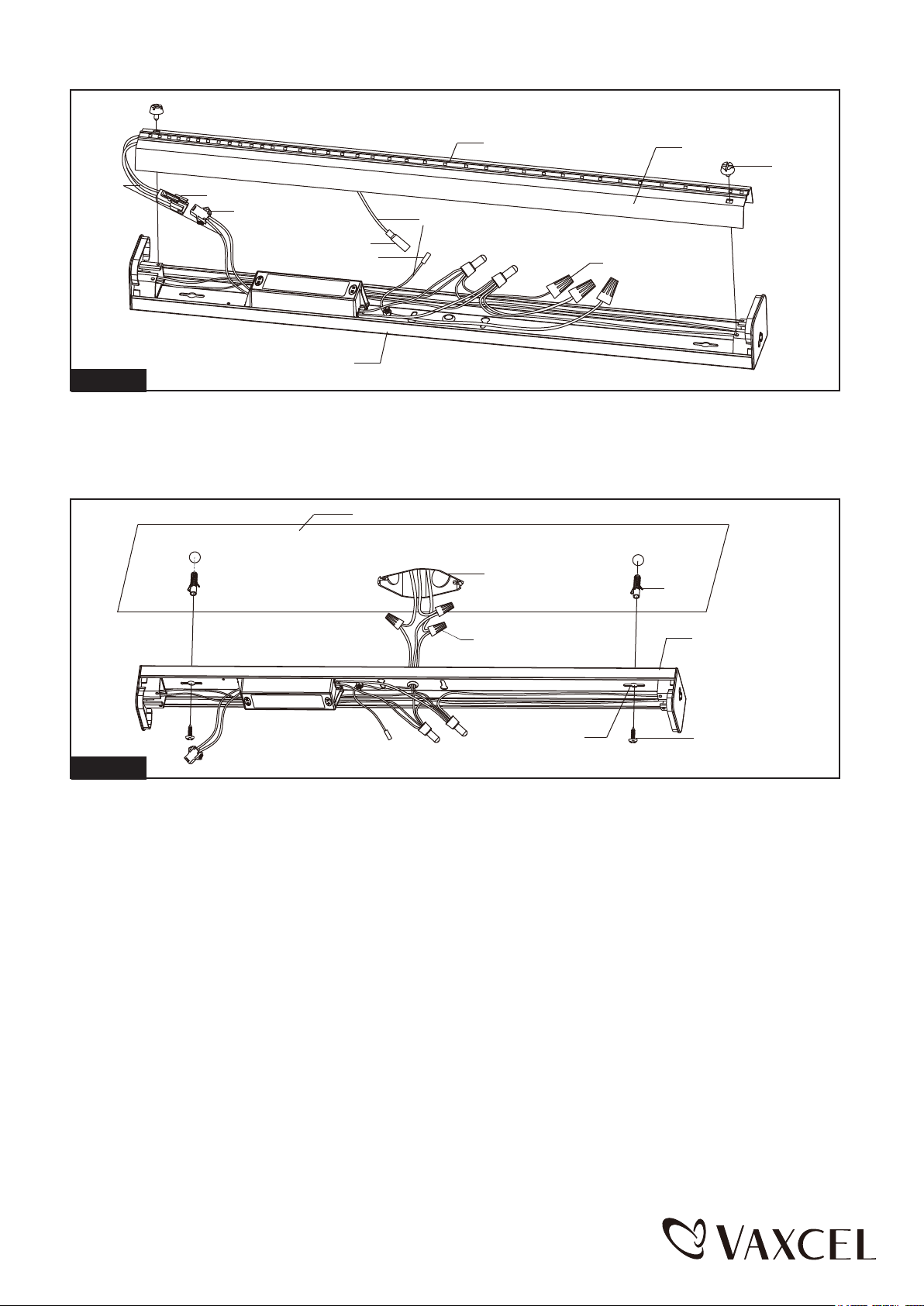
Terminal
Wire
Female Connector
Male Connector
Female Connector
Male Connector
Fixture Plate
LED Strip
Grounding Wire
Wire Connector
Aluminium Plate
Set Screw
Fig.2
2. Remove the set screws on each side and then detach the aluminum plate. Remove the hardware pack from
fixture, unplug two connectors to separate the terminal wires and grounding wire inside the fixture plate.
Ceiling
Outlet Box
Wire Connector
Anchor(A)
Fixture Plate
Dry Wall Screw (B)Key hole slot
Fig.3
3. Attach the fixture plate to the location where you want to install, mark the target where is for two anchors to
secure fixture plate to the ceiling. Remove the fixture plate and drill two holes on the target, hammer the anchors
to target holes tightly, then secure the dry wall screws to anchors in part way. (See Fig.3)
4. Remove three wire connectors from three wires, then thread these three wires through the center hole of fixture
plate.(See Fig.3)
5.
Pull out the source wires from the outlet box. Make wire connections using wire connectors as follows:
---Connect the hot wire (usually black insulation) from the fixture to the black wire from the power source.
---Connect the neutral wire (usually white insulation) from the fixture to the white wire from the power source.
---Connect the fixture grounding wire (usually green insulation or bare wire) to the house grounding wire from the
power source.
Carefully put the wires back into the outlet box.
(See Fig.3)
6. Attach fixture plate to ceiling by inserting two dry wall screw heads into key hole slots, then slide the fixture plate
to left or right until the heads of the dry wall screw are located into narrow ends of the key hole slot. (See Fig.3)
7. Use a screwdriver (not included) to tighten the dry wall screws. (See Fig.3)
171207
Page 3
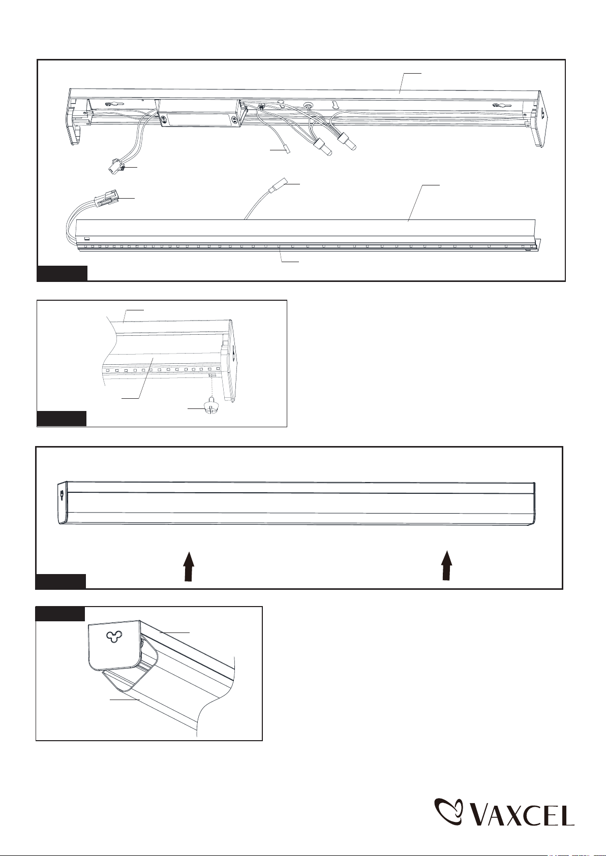
Male Connector
Fixture Plate
Male Connector
Fig.4
Aluminium Plate
Fig.5
Female Connector
Fixture Plate
Set Screw
Female Connector
LED Strip
8.
Plug the male connectors into female connectors. Attach
Aluminium Plate
the aluminium plate to fixture plate, and then secure it with
two set screws. (See Fig.4,5)
Fig.6
Fig.7
PC Diffuser
Fixture Plate
9. Attach the PC diffuser back to fixture plate, withhold one side
of PC diffuser into fixture plate, then squeez and push the other
side of PC diffuser to fixture plate. (See Fig.6,7)
171207
Page 4
Connecting fixture to fixture:
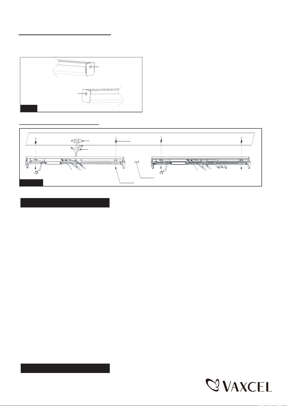
The LED strip lighting fixtures can be connected together in series using included plastic connector or linking cord.
Link up to 24pcs x 24" bar lights (#H0195) together, link up to 24pcs x 48" bar lights (#H0196) together or link
combination of sizes together.
Plastic Plug
Remove the plastic plugs from fixtures, where need plug
plastic connector or linking cord into LED light fixture.
The First Fixture
Plastic Plug
Fig.8
The Second Fixture
A. Using plastic connector:
Outlet Box
Wire Connector
The First Fixture Plate
Fig.9
Using plastic connectors to connect two more LED strip lighting fixtures: (Take two fixtures as example)
Turn off the power at fuse or circuit box.
Anchor(A)
Plastic Connector(D)
Dry Wall Screw(B)
The Second Fixture Plate
1. Follow step 1,2 of instructions of single fixture installation.
2. Plug the plastic connector into the first fixture, and then connect with the second fixture.
3. Attach the two connected fixture plates to the location where you want to install, mark the target where is for four
anchors to secure connected fixture plates to the ceiling. Remove the connected fixture plates and drill four holes
on the target, hammer the anchors to target holes tightly, then secure the dry wall screws to anchors in part way.
(See Fig.9)
4. Remove three wire connectors from three wires in the first fixture, then thread these three wires through the
center hole of the first fixture plate.(See Fig.9)
5.
Pull out the source wires from the outlet box. Make wire connections using wire connectors as follows:
---Connect the hot wire (usually black insulation) from the fixture to the black wire from the power source.
---Connect the neutral wire (usually white insulation) from the fixture to the white wire from the power source.
---Connect the fixture grounding wire (usually green insulation or bare wire) to the house grounding wire from the
power source.
Carefully put the wires back into the outlet box.
(See Fig.9)
6. Attach connected fixture plates to ceiling by inserting four dry wall screw heads, then slide the connected fixture
plates together to left or right until the heads of the dry wall screw are located into narrow ends of the key hole
slot. (See Fig.9)
7. Use a screwdriver (not included) to tighten the dry wall screws. (See Fig.9)
8. Follow step 8,9 of instructions of single fixture installation for two fixtures.
Turn on the power at fuse or circuit box.
171207
Page 5
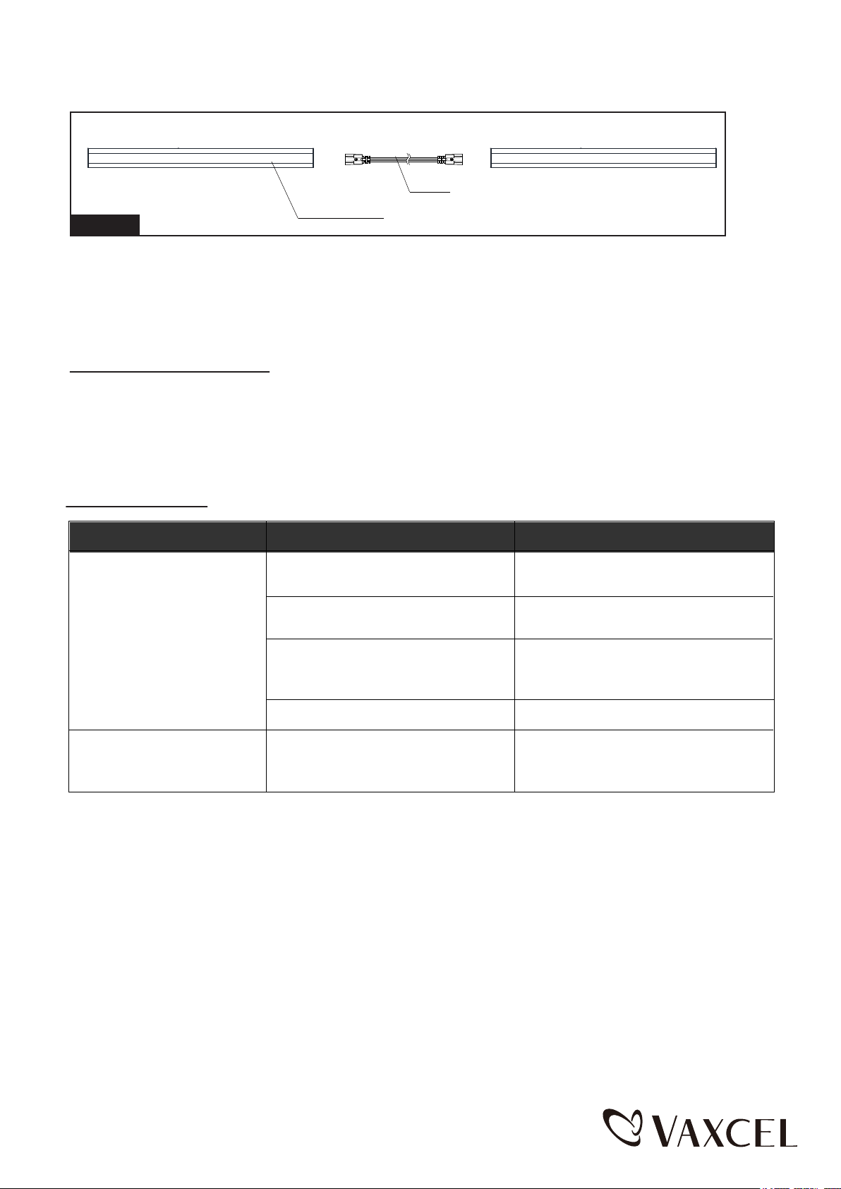
B. Using linking cord:
Previously Installed Fixture
Fig.10
Using linking cord to connect two more LED strip lighting fixtures:
Each additional fixture (not included) should be mounted in the same way as the previously installed fixture.
Once installed, attach the linking cord (12 inches) into the input receptacles between the previously installed
fixture and the additional fixture . (See Fig.10)
Make sure the distance between LED strip lighting fixtures does not exceed the linking cord length.
LED Strip Lighting Fixture
Linking Cord (C)
Additional Fixture
Care and Maintenance
Caution: Before attempting to clean the fixture, disconnect the power to the fixture by turning the breaker
off or removing the fuse from the fuse box.
This LED light fixture is made from quality materials that will last many years with minimum care. You may
want to periodically clean the fixture with a soft cloth. To maintain the best appearance of the fixture, do
not use cleaners with chemicals, solvents or harsh abrasives. Do not use liquid cleaner on the LEDs, LED
drive, or wiring inside the light fixture.
Troubleshooting
PROBLEM
POSSIBLE CAUSE CORRECTIVE ACTION
The power is off.
Check to ensure the power
supply is on
The fixture will not light
The fuse blows or circuit
breaker tips when the light
is turn on.
The circuit breaker is off.
There is a bad connection.
There is a defective switch.
The wires are crossed or the power
wire is grounding out.
Check to ensure the circuit
breaker is in the on position
Check to ensure proper wire
connections are made. Contact a
qualified electrician.
Contact a qualified electrician.
Check to ensure proper wire
connections are made. Contact a
qualified electrician.
171207
Page 6
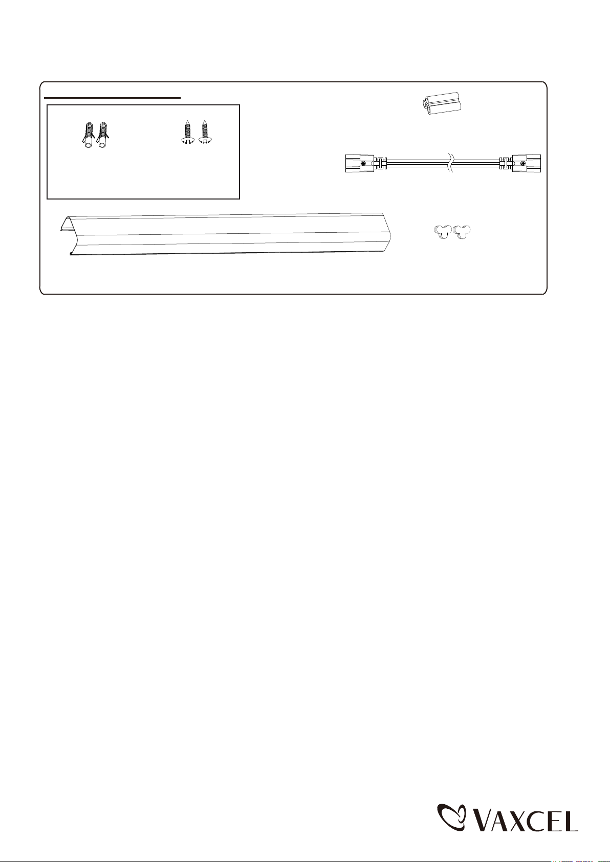
The following parts are available for re-order if damaged or missing.
Contents of Spare Parts:
Plastic Connector(D)
7120PC(1PC)
Assembly Kit
5403MM (1 SET)
Linking Cord (C)
7121LC(1PC)
Anchor (A)
Dry Wall Screw(B)
Plastic Lens
9743PL(1PC) FOR H0195
9744PL(1PC) FOR H0196
Plastic Plug
5413PA (2PCS)
5-YEAR LIMITED WARRANTY:
All products are warranted to be free of defects in material and workmanship for five (5) years from date of
purchase. This warranty is limited to the correction of any such defect, or the replacement of any such defective
item(s), provided that: (a) we are properly notified and consent to return of the item(s) in question:(b) the item (s)
is / are returned with proof of purchase date; and (c) it is found upon inspection by us that the item (s) is / are defective
as noted above. This warranty dose not cover labor costs, consequential damages, nor dose it apply to any item(s) that
have been improperly installed, overloaded, altered, or otherwise abused by the customer, its agent(s) or emplyee(s).
Finishes are specially excluded from the terms of this warranty since they are subject to environmental maintenance
deemed beyond our control. Other than the described obligation, we assume no further liability with respect to the sale
or use of our products.We make no warranty, express or implied, and disclaim any warranty of merchantability or fitness
for a particular purpose.
171207
 Loading...