

Page 1
Page 2

Page 3

SA 160
AIRCRAFTA I R C R A F T
Symphony
APPLICABILITY / REVISIONS
APPLICABILITY
i
Feb 25, 2005
This handbook contains information applicable to the model SA 160
aircraft designated by serial number and registration number shown on
thetitlepage.
All information is based on data available at the time of delivery of your
aircraftby SymphonyAircraft IndustriesInc.
NOTE: A current handbook must be in the aircraft during flight. It
is theoperator's responsibility to maintainthe handbook in
acurrentstatus.
The information in this handbook will be kept current by revisions
issuedby .
Revision materialwill contain information necessary toupdate the text,
figures,and chartsof thepresent handbookand /or addinformation.
1.Incorporating Revisions
Revisions must be incorporated as they are issued. Revision status is
noted on List of Revisions page and Log of Effective Pages table in this
section.
Revisionsshall beinserted intothe handbookas follows:
(a) Alwaysreplace pageswith revisionpages ofsame pagenumber.
(b) Insert additional pages in correct numerical order within each
section.
Revisions
SymphonyAircraft Industries
Page 4

SA 160
AIRCRAFTA I R C R A F T
Symphony
ii
APPLICABILITY / REVISIONS
2.Identification ofRevised Material
Revisions, additions and deletions will be identified by a vertical black
line alongthe outsideof thepage oppositeonly the portion ofthe printed
matterthat waschanged.
A line along the outside margin of the page beside the page number
indicatesthat non-changedmaterial hasa newphysical locationonly.
Thedate ofthe revisionis shownon eachrevised page.
Feb 25, 2005
Page 5

SA 160
AIRCRAFTA I R C R A F T
Symphony
The following Log of Effective Pages provides a listing of all effective
pages in the POH, as well as the date of issue or revision.
Revision Level Date of Issue
0 (Original Issue) Feb 25, 2005
PAGE DATE PAGE DATE
iii
Title Feb 25, 2005
i Feb 25, 2005
ii Feb 25, 2005
iii Feb 25, 2005
iv Feb 25, 2005
vi Feb 25, 2005
vii Feb 25, 2005
viii Feb 25, 2005
ix Feb 25, 2005
x Feb 25, 2005
xi Feb 25, 2005
1-1 Feb 25, 2005
1-2 Feb 25, 2005
1-3 Feb 25, 2005
1-4 Feb 25, 2005
1-5 Feb 25, 2005
1-6 Feb 25, 2005
v Feb 25, 2005
1-7 Feb 25, 2005
1-8 Feb 25, 2005
1-9 Feb 25, 2005
1-10 Feb 25, 2005
1-11 Feb 25, 2005
1-12 Feb 25, 2005
1-13 Feb 25, 2005
1-14 Feb 25, 2005
2-1 Feb 25, 2005
2-2 Feb 25, 2005
2-3 Feb 25, 2005
2-4 Feb 25, 2005
2-5 Feb 25, 2005
2-6 Feb 25, 2005
2-7 Feb 25, 2005
2-8 Feb 25, 2005
2-9 Feb 25, 2005
2-10 Feb 25, 2005
LOG OF EFFECTIVE PAGES
LOG OF EFFECTIVE PAGES
Feb 25, 2005
Page 6

SA 160
AIRCRAFTA I R C R A F T
Symphony
iv
2-11 Feb 25, 2005
2-12 Feb 25, 2005
3-1 Feb 25, 2005
3-2 Feb 25, 2005
3-3 Feb 25, 2005
3-4 Feb 25, 2005
3-5 Feb 25, 2005
3-6 Feb 25, 2005
3-7 Feb 25, 2005
3-8 Feb 25, 2005
3-9 Feb 25, 2005
3-10 Feb 25, 2005
3-11 Feb 25, 2005
3-12 Feb 25, 2005
3-13 Feb 25, 2005
3-14 Feb 25, 2005
3-15 Feb 25, 2005
3-16 Feb 25, 2005
3-17 Feb 25, 2005
3-18 Feb 25, 2005
4-1 Feb 25, 2005
4-2 Feb 25, 2005
4-3 Feb 25, 2005
4-4 Feb 25, 2005
4-5 Feb 25, 2005
4-6 Feb 25, 2005
4-7 Feb 25, 2005
4-8 Feb 25, 2005
4-9 Feb 25, 2005
3-19 Feb 25, 2005
3-20 Feb 25, 2005
3-21 Feb 25, 2005
4-10 Feb 25, 2005
4-11 Feb 25, 2005
4-12 Feb 25, 2005
4-13 Feb 25, 2005
4-14 Feb 25, 2005
4-15 Feb 25, 2005
4-16 Feb 25, 2005
4-17 Feb 25, 2005
4-18 Feb 25, 2005
4-19 Feb 25, 2005
4-20 Feb 25, 2005
4-21 Feb 25, 2005
4-22 Feb 25, 2005
4-23 Feb 25, 2005
4-24 Feb 25, 2005
4-25 Feb 25, 2005
4-26 Feb 25, 2005
4-27 Feb 25, 2005
4-28 Feb 25, 2005
4-29 Feb 25, 2005
4-30 Feb 25, 2005
4-31 Feb 25, 2005
4-32 Feb 25, 2005
5-1 Feb 25, 2005
5-2 Feb 25, 2005
5-3 Feb 25, 2005
5-4 Feb 25, 2005
5-5 Feb 25, 2005
5-6 Feb 25, 2005
5-7 Feb 25, 2005
5-8 Feb 25, 2005
5-9 Feb 25, 2005
PAGE DATE PAGE DATE
LOG OF EFFECTIVE PAGES
Feb 25, 2005
Page 7

SA 160
AIRCRAFTA I R C R A F T
Symphony
v
5-10 Feb 25, 2005
5-11 Feb 25, 2005
5-12 Feb 25, 2005
5-13 Feb 25, 2005
5-14 Feb 25, 2005
5-15 Feb 25, 2005
5-16 Feb 25, 2005
5-17 Feb 25, 2005
5-18 Feb 25, 2005
5-19 Feb 25, 2005
5-20 Feb 25, 2005
5-21 Feb 25, 2005
5-22 Feb 25, 2005
6-1 Feb 25, 2005
6-2 Feb 25, 2005
6-3 Feb 25, 2005
6-4 Feb 25, 2005
6-5 Feb 25, 2005
6-6 Feb 25, 2005
6-7 Feb 25, 2005
6-8 Feb 25, 2005
6-9 Feb 25, 2005
6-10 Feb 25, 2005
6-11 Feb 25, 2005
6-12 Feb 25, 2005
6-13 Feb 25, 2005
7-1 Feb 25, 2005
7-2 Feb 25, 2005
7-3 Feb 25, 2005
5-23 Feb 25, 2005
5-24 Feb 25, 2005
6-14 Feb 25, 2005
7-4 Feb 25, 2005
7-5 Feb 25, 2005
7-6 Feb 25, 2005
7-7 Feb 25, 2005
7-8 Feb 25, 2005
7-9 Feb 25, 2005
7-10 Feb 25, 2005
7-11 Feb 25, 2005
7-12 Feb 25, 2005
7-13 Feb 25, 2005
7-14 Feb 25, 2005
7-15 Feb 25, 2005
7-16 Feb 25, 2005
7-17 Feb 25, 2005
7-18 Feb 25, 2005
7-19 Feb 25, 2005
7-20 Feb 25, 2005
7-21 Feb 25, 2005
7-22 Feb 25, 2005
7-23 Feb 25, 2005
7-24 Feb 25, 2005
7-25 Feb 25, 2005
7-26 Feb 25, 2005
7-27 Feb 25, 2005
7-28 Feb 25, 2005
7-29 Feb 25, 2005
7-30 Feb 25, 2005
7-31 Feb 25, 2005
7-32 Feb 25, 2005
7-33 Feb 25, 2005
7-34 Feb 25, 2005
7-35 Feb 25, 2005
PAGE DATE PAGE DATE
LOG OF EFFECTIVE PAGES
Feb 25, 2005
Page 8

SA 160
AIRCRAFTA I R C R A F T
Symphony
vi
7-36 Feb 25, 2005
7-37 Feb 25, 2005
7-38 Feb 25, 2005
7-39 Feb 25, 2005
7-40 Feb 25, 2005
7-41 Feb 25, 2005
7-42 Feb 25, 2005
7-43 Feb 25, 2005
7-44 Feb 25, 2005
7-45 Feb 25, 2005
7-46 Feb 25, 2005
7-48 Feb 25, 2005
7-49 Feb 25, 2005
8-1 Feb 25, 2005
8-2 Feb 25, 2005
8-3 Feb 25, 2005
8-4 Feb 25, 2005
8-5 Feb 25, 2005
8-6 Feb 25, 2005
8-7 Feb 25, 2005
8-8 Feb 25, 2005
8-9 Feb 25, 2005
8-10 Feb 25, 2005
8-11 Feb 25, 2005
8-12 Feb 25, 2005
8-13 Feb 25, 2005
8-14 Feb 25, 2005
7-50 Feb 25, 2005
7-51 Feb 25, 2005
7-52 Feb 25, 2005
7-53 Feb 25, 2005
7-54 Feb 25, 2005
8-15 Feb 25, 2005
8-16 Feb 25, 2005
8-17 Feb 25, 2005
LOG OF EFFECTIVE PAGES
PAGE DATE PAGE DATE
Feb 25, 2005
Page 9

SA 160
AIRCRAFTA I R C R A F T
Symphony
vii
LOG OF EFFECTIVE PAGES
INTENTIONALLY LEFT BLANK
Feb 25, 2005
Page 10

SA 160
AIRCRAFTA I R C R A F T
Symphony
viii
LOG OF EFFECTIVE PAGES
INTENTIONALLY LEFT BLANK
Feb 25, 2005
Page 11

SA 160
AIRCRAFTA I R C R A F T
Symphony
ix
LIST OF REVISIONS
LIST OF REVISIONS
Description
Page
No.
Date
Rev.
No.
Feb 25, 2005
Approval
Page 12

SA 160
AIRCRAFTA I R C R A F T
Symphony
x
LIST OF REVISIONS
INTENTIONALLY LEFT BLANK
Feb 25, 2005
Page 13

SA 160
AIRCRAFTA I R C R A F T
Symphony
xi
CONTENTS
CONTENTS
SECTION
GENERAL............................1
LIMITATIONS .........................2
EMERGENCY PROCEDURES ................3
NORMAL PROCEDURES ..................4
PERFORMANCE........................5
WEIGHT AND BALANCE
EQUIPMENT LIST.......................6
DESCRIPTION AND OPERATION
OF THE AIRCRAFT AND ITS SYSTEMS ..........7
HANDLING, SERVICING AND
MAINTENANCE ........................8
SUPPLEMENT .........................9
Feb 25, 2005
Page 14

SA 160
AIRCRAFTA I R C R A F T
Symphony
Page 15

SA 160
AIRCRAFTA I R C R A F T
Symphony
SECTION 1
GENERAL
1-1
SECTION 1
GENERAL
TABLE OF CONTENTS
Page
Aircraft Views (3) ..............................................................................1-2
1.1 Introduction..........................................................................................1-4
1.3 Technical Data ......................................................................................1-5
Engine.................................................................................................1-5
Propeller.............................................................................................1-5
Fuel......................................................................................................1-5
Oil........................................................................................................1-6
Maximum Certificated Weights......................................................1-6
Typical Aircraft Weights...................................................................1-6
Cabin and Entry Dimensions .........................................................1-7
Baggage Space...................................................................................1-7
Specific Loadings..............................................................................1-7
Other Data .........................................................................................1-7
1.5 Symbols, Abbreviations and Terminology .......................................1-8
(a) General Airspeed Terminology and Symbols......................1-8
(b) Meteorological Terminology ................................................1-10
(c) Power Terminology................................................................1-11
(d) Engine Instruments ...............................................................1-11
(e) Aircraft Performance and Flight
Planning Terminology...........................................................1-11
(f) Weight and Balance...............................................................1-12
(g) Other Definitions ...................................................................1-14
Feb 25, 2005
Page 16

SA 160
AIRCRAFTA I R C R A F T
Symphony
AIRCRAFT VIEWS
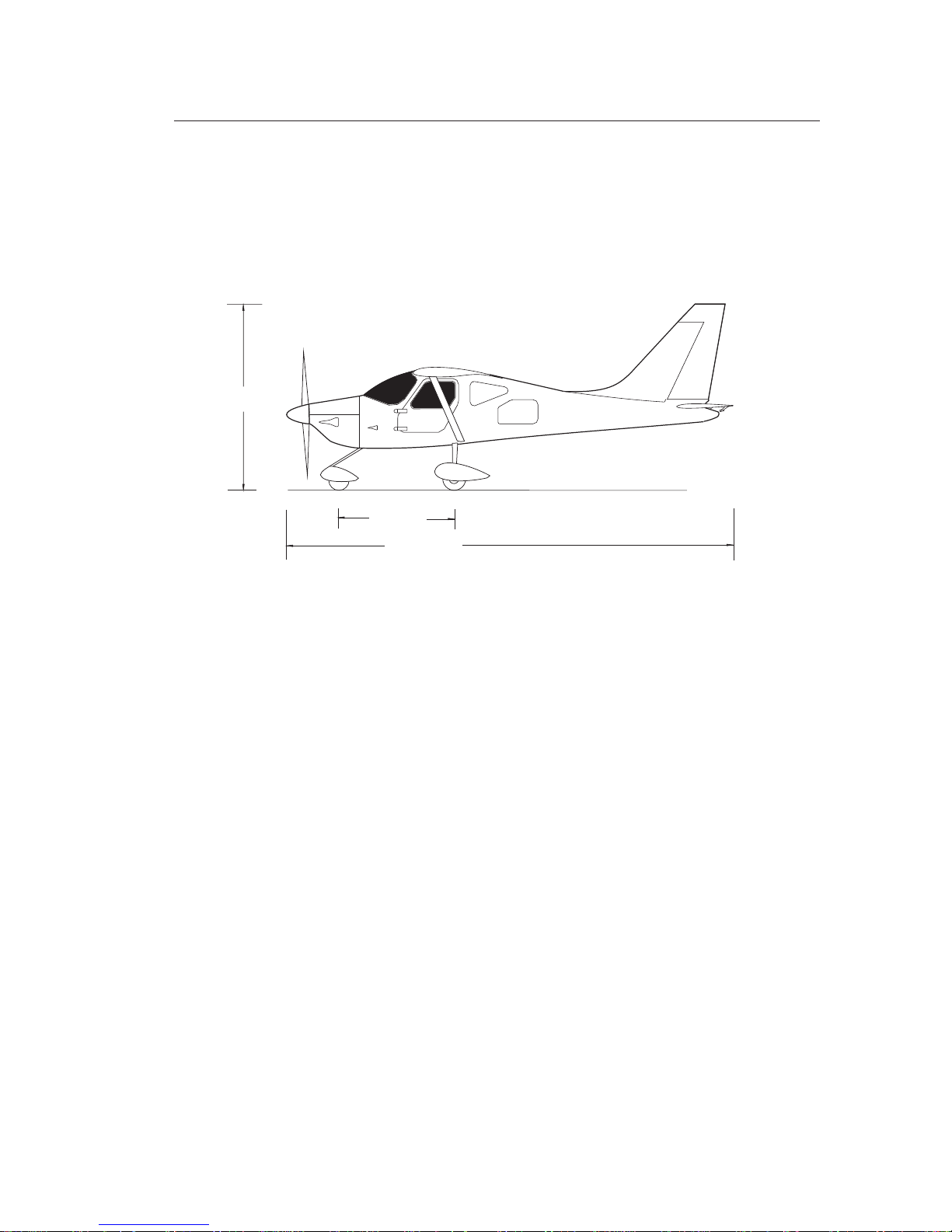
Abb. 1-1(1)
Aircraft Views
1-2
10.67 (35)
2.11 (6.92)
1.118 (3.67)
3.27 (10.75)
0.86 (2.82)
m (ft.)
SECTION 1
GENERAL
Feb 25, 2005
Page 17
SA 160
AIRCRAFTA I R C R A F T
Symphony
Abb. 1-1(2)
Aircraft Views
1-3
2.82 (9.25)
1.72 (5.67)
6.960 (22.84)
SECTION 1
GENERAL
Notes:
The ground clearance of the propeller at maximum takeoff weight and
in the takeoff attitude is at least 0.180 m (7 in.). Maximum propeller
diameteris 1.854m (73in.).
Thewing areais 11.93m² (128.4sq.ft.).
A minimum turning radius of 6.6 m (21.7 ft) (Pivot point to the wing
tip) can be achieved.
Control Surface Deflections:
- Aileron Up 23° - Down 17°;
- Elevator Up 21° - Down 20°;
- Rudder Left 21°- Right 21°;
- Trim Tab Up 10° - Down 20°;
- Flaps - Down 0° to 40°.
Feb 25, 2005
Page 18

SA 160
AIRCRAFTA I R C R A F T
Symphony
1-4
1.1 INTRODUCTION
SECTION 1
GENERAL
This manual constitutes a Transport Canada approved Airplane Flight
Manualfor Canadianregistered airplanesin accordancewith AWM 523.
In countries other than Canada, Transport Canada operating rules may
not apply. Operators must ensure that the aircraft is operated in
accordancewith nationaloperating rules.
The manual is divided into 8 sections and contains data for the pilot that
must be available in accordance with the CARs. Supplementary
specificationsof theaircraft manufacturerare alsoincluded.
The handbook is intended to familiarize the pilot with the aircraft,
operating limits, emergency procedures, normal procedures and
performance.
The handbook does not serve as a substitute for appropriate flight
training and knowledge of valid airworthiness advisories, the relevant
official aviation rules and the advisory circulars. It is not intended as
orientation for flight, basic training, or as a training manual, and it may
onlybe usedas thecurrentstatus for theoperationof theAircraft.
The handbook is divided into sections, which are numbered with Arabic
digits. Each section is divided by separator sheets for speedy reference.
The operating limitsand theemergency proceduresare placedbefore the
normal procedures, the performance data and the other sections. The
section "Emergency Procedures" is marked witha red tab divider so that
thissection canbe lookedup immediately.
Provision for an extension to the handbook is provided. Therefore, some
paragraph numbers, figure numbers, position numbers and pages are
deliberatelyomitted andannotated "Intentionally leftblank".
Feb 25, 2005
Page 19

SA 160
AIRCRAFTA I R C R A F T
Symphony
1.3 TECHNICAL DATA
1-5
SECTION 1
GENERAL
Engine
Propeller
Fuel
(a) Number 1
(b) Engine Manufacturer Textron Lycoming.
(c) Engine Model O-320-D2A
(d) Engine Type Four cylinder, direct drive,
horizontally opposed,
air cooled engine with
a float type carburetor
(e) Rated Power 119 kW (160 BHP)
(f) Rated Speed 2700 RPM
(g) Bore 130.175 mm (5.125 in.)
(h) Stroke 98.425 mm (3.875 in.)
(i) Displacement 5.24 l (319.8 cu.in.)
(j) Compression Ratio 8.5:1
(a) Number 1
(b) Propeller Manufacturer MT-propeller
(c) Propeller Model MT 186 R 140-3D P-244-3
(d) Number of Blades 2
(e) Propeller Diameter 1860 mm, (73.2)
(f) Propeller Type Wood, fixed pitch
(a) Fuel Approved Fuel Grades
AVGAS 100 LL blue
(b) Total Capacity 122 l (32.2 U.S. Gal)
(c) Total Usable 110 l (29.1 U.S. Gal)
Feb 25, 2005
Page 20

SA 160
AIRCRAFTA I R C R A F T
Symphony
1-6
SECTION 1
GENERAL
Oil
Maximum Certified Weights
Typical Aircraft Weights
(a) Oil Specification Aviation Grade Straight
Mineral Oil MIL-L-6082
and Aviation Grade Ashless
Dispersant Oil MIL-L-22851
(b) Oil Viscosity
Mean Environment- MIL-L-6082 MIL-L-22851
Temperature Ashless Dispersant
Above 16°C (60°F) SAE 50 SAE 40 or SAE 50
-1°C to 32°C SAE 40 SAE 40
-18°C to 21°C SAE 30 SAE 30 or SAE 40
Below -12°C SAE 20 SAE 30
(c) Max. Oil Capacity 7.6 l (8 qt)
(d) Recommended Oil Quantity 4.7 - 6.6 l (5 -7 qt)
(a) Maximum Ramp Weight 975 kg (2150 lbs)
(b) Maximum Takeoff Weight 975 kg (2150 lbs)
(c) Landing Weight 926 kg (2041 lbs)
(d) Maximum Weight in Baggage Compartment 75 kg (165 lbs)
but in the front or rear area maximum 45 kg (99 lbs)
(a) Empty Weight depending
630 - 660 kg (1389 - 1455 lbs)
(b) Maximum Useful Load 345 kg (761 lbs)
(30°F) (90°F)
(0°F) (70°F)
(10°F)
on installed equipment:
Feb 25, 2005
Page 21

SA 160
AIRCRAFTA I R C R A F T
Symphony
1-7
SECTION 1
GENERAL
Cabin and Entry Dimensions
Baggage Spaces
Specific Loadings
(a) Maximum Cabin Width 1.10 m (43.3 in.)
(b) Maximum Cabin Length 1.22 m (48.0 in.)
(c) Maximum Cabin Height 1.14 m (44.8 in.)
(d) Maximum Entry Width 0.805 m (31.7 in.)
(e) Maximum Entry Height 0.80 m (31.5 in.)
(f) Maximum Sill Height 0.838 m (33 in.)
(a) Compartment Width 0.44 m (17.3 in.) - 0.87 m (34.3 in.)
(b) Compartment Length 1.255 m (49.4 in.)
(c) Compartment Height 0.45 m (17.7 in.) - 0.77 m (30.3 in.)
(a) Volume 870 l (30.72 cu.ft)
(a) Wing Area Loading 81.7 kg/m (16.73 lbs/sq.ft.)
(b) Power Loading Takeoff Power (N) / 975 x 9.81 (N) = 0.122
= 8.19 kg/kW (13.89 lbs/hp)
2
Feb 25, 2005
Page 22

SA 160
AIRCRAFTA I R C R A F T
Symphony
1-8
SECTION 1
GENERAL
1.5 SYMBOLS, ABBREVIATIONS
AND TERMINOLOGY
The followingdefinitions arefor symbols,abbreviation, and terms which
are used in this handbook or are relevant for the pilot during the
operationof theAircraft.
means the indicated speed of an aircraft,
corrected for position and instrument error. CAS is equal to TAS in
standardatmosphere atsea level.
CalibratedAirspeed expressedin "knots”.
isthe speedrelative tothe ground.
is thespeed ofan aircraftas shownon the airspeed
indicator whencorrectedfor instrument error. IASvalues published
inthis Handbookassume zeroinstrumenterror.
IndicatedAirspeed expressedin "knots".
isthe ratioof true airspeedto thespeed ofthe sound.
is the airspeed of anAircraft relative to undisturbedair
which is the CAS corrected for altitude, temperature and
compressibility.
(a) General Airspeed Terminology and Symbols
CAS
KCAS
GS
IAS
KIAS
M
TAS
Calibrated Airspeed
Ground Speed
Indicated Airspeed
Mach Number
Tr ue Airspeed
Feb 25, 2005
Page 23

SA 160
AIRCRAFTA I R C R A F T
Symphony
1-9
SECTION 1
GENERAL
V/V
AO
Maneuvering Speed
Maximum Flap Extended Speed
Never Exceed Speed
Maximum Structural Cruising Speed
Stall Speed
Stall Speed with flap
Best Angle-of-Climb Speed
Best Rate-of-Climb Speed
V
V/M
V
V
V
V
V
is the maximum speed at which application of
fullavailable aerodynamiccontrol willnot overstressthe Aircraft.
is the highest speed permissible with
wingflaps ina prescribedextended position.
or Mach Number is the speed limit that may not
beexceeded atany time.
is the speed that should not be
exceededexceptin smoothair andthen onlywith caution.
or the minimum steady flight speed at which the Aircraft
iscontrollable.
orthe minimumsteady flight speedat whichthe
Aircraftis controllablein thelanding configuration.
is the airspeed which delivers the greatest
gainof altitudein theshortest possiblehorizontal distance.
is the airspeed which delivers the greatest
gainin altitudein theshortest possibletime.
FE
NE NE
NO
S
SO
x
Y
Feb 25, 2005
Page 24

SA 160
AIRCRAFTA I R C R A F T
Symphony
1-10
SECTION 1
GENERAL
(b) Meteorological Terminology
ISA
OAT
MSN
Indicated Pressure Altitude
Pressure Altitude
Station Pressure
International StandardAtmosphere
Outside Air Temperature
inwhich
(1) The airis adry perfect gas;
(2) The temperatureat sealevel is15° Celsius(59° Fahrenheit);
(3) The pressureat sealevel is29.92 inchesh g.(1013.2mb);
(4) The temperature gradient from sea level to the altitude at which
thetemperature is-56.5°C (-69.7°F) is- 0.00198°C
(- 0.003564°F)per footand zeroabove thataltitude.
is the free air static temperature, obtained
either from inflight temperature indications or ground
meteorological sources, adjusted for instrument error and
compressibilityeffects.
Mean Sea Level
The number actually read from an altimeter when the barometric
subscalehas beenset to29.92 inchesof mercury (1013.2mb).
Altitudemeasured fromstandardsea levelpressure(29.92 in.hg.)by
a pressure or barometric altimeter. It is the indicated pressure
altitude corrected for position and instrument error. In this
Handbook,altimeter instrument errorsare assumedto bezero.
Actualair pressureat fieldelevation.
Feb 25, 2005
Page 25

SA 160
AIRCRAFTA I R C R A F T
Symphony
1-11
SECTION 1
GENERAL
(c) Power Terminology
(d) Engine Instruments
(e) Aircraft Performance and Flight Planning Terminology
Takeoff Power
Maximum Continuous Power
Cruise Climb Power
Maximum Cruise Power
EGT-Indicator
CHT-Indicator
Climb Gradient
Themaximum powerpermissible fortakeoff(may betime limited).
Highestpower setting,not limitedby time.
Powerrecommended forcruise climb.
The maximum power setting for which specific values of fuel flow
andairspeed arepresented.
ExhaustGas TemperatureIndicator
Cylinder Heat Temperature Indicator
The demonstrated ratio of the change in height during a portion of
a climb, to the horizontal distance traversed in the same time
interval
Feb 25, 2005
Page 26

SA 160
AIRCRAFTA I R C R A F T
Symphony
1-12
SECTION 1
GENERAL
Demonstrated Crosswind Velocity
Accelerate-StopDistance
Route Segment
MEA
Reference Datum
Station
Arm
The demonstrated crosswind velocity is the velocity of the
crosswindcomponent forwhich adequatecontrol ofthe Aircraft
during takeoff and landing was actually demonstrated during
certificationtests.
The distance required to accelerate an Aircraft to a specified speed
and, assuming failure of an engine at the instant that speed is
attained,to bringthe Aircraftto astop.
A part of a route. Each end of that part is identified by: (1) a
geographical location;or (2) apoint at whicha definite radiofix can
beestablished.
Minimumenroute IFRaltitude.
An imaginary vertical plane from which all horizontal distances are
measuredfor balancepurposes.
A location along the Aircraft fuselage usually given in terms of
distancefrom thereference datum.
The horizontal distance from the reference datum to the center of
gravity(C.G.) ofan item.
(f) Weight and Balance
Feb 25, 2005
Page 27

SA 160
AIRCRAFTA I R C R A F T
Symphony
1-13
SECTION 1
GENERAL
Moment
Center of gravity (C.G.)
C.G. Arm
C.G. Limits
Usable Fuel
Unusable Fuel
Standard Empty Weight
Basic Empty Weight
Useful load
,
The productof theweight ofan itemmultiplied byits arm.(Moment
divided by a constant is used to simplify balance calculations by
reducingthe numberof digits.)
The point at which an Aircraft would balance if suspended. Its
distance from the reference datum is found by dividing the total
momentby thetotal weightof theAircraft.
The arm obtained by adding the Aircraft's individual moments and
dividingthe sumby thetotal weight.
The extreme center of gravity locations within which the Aircraft
mustbe operatedat agiven weight.
Fuelavailable forflight planningpurposes.
Fuel remaining after a run out test has been completed in
accordancewith governmental regulations.
Weightof astandard Aircraftincluding unusablefuel, fulloperating
fluidsand fulloil.
Standardempty weightplus optionalequipment.
Difference between take off weight, or ramp weight if applicable
andbasic emptyweight.
Feb 25, 2005
Page 28

SA 160
AIRCRAFTA I R C R A F T
Symphony
Payload
Maximum Ramp Weight
Maximum Takeoff Weight
Maximum Landing Weight
Maximum Zero Fuel Weight
Weightof occupants,cargo andbaggage.
Maximum weight approved for ground maneuvre. (It includes
weightof start,taxi andrun upfuel.)
Maximumweight approvedfor thestart ofthe takeoffrun.
Maximumweight approvedfor thelanding touchdown.
Maximumweight exclusiveof usablefuel.
Methods, proceduresor limitswhich must befollowed precisely
toavoid injury ordeath.
(g) Other Definitions
1-14
CAUTION !
WARNING !
SECTION 1
GENERAL
Methods, procedures or limits which must be followed to avoid
damageto equipment.
Additionalprocedures orinformation pertainingto thetext.
NOTE:
Feb 25, 2005
Page 29

SA 160
AIRCRAFTA I R C R A F T
Symphony
SECTION 2
LIMITATIONS
2-1
SECTION 2
LIMITATIONS
TABLE OF CONTENTS
2.1 General..................................................................................................2-2
2.3 Airspeed Limitations...........................................................................2-2
2.5 Airspeed Indicator Markings.............................................................2-3
2.7 Power Plant Limitations .....................................................................2-4
2.9 Engine Parameter Color Markings...................................................2-5
2.11 Weight Limits .......................................................................................2-6
2.13 Center of Gravity Limits.....................................................................2-6
2.15 Maneuver Limits .................................................................................2-6
2.17 Flight Load Factor Limits ...................................................................2-7
2.19 Crew ......................................................................................................2-7
2.21 Kinds of Operations............................................................................2-7
2.23 Fuel Limitations...................................................................................2-8
2.29 Placards .................................................................................................2-9
2.25 Other Limitations ................................................................................2-8
(a) Airframe.....................................................................................2-8
2.27 Temperature Limitation ......................................................................2-8
Feb 25, 2005
Page 30

SA 160
AIRCRAFTA I R C R A F T
Symphony
2.1 GENERAL
2.3 AIRSPEED LIMITATIONS
2-2
This section contains the operating limits (approved by the regulatory
authority), the instrument markings, the color coding and the most
important placards that are necessary for the safe operation of the
aircraft,engine, systems,and theaircraft's standardequipment.
The Chapter 4 "Airworthiness" of the SA 160 Maintenance Manual
containsthe prescribedlimitations concerning themaintenance.
The aircraft must be operated in compliance with these operating limits,
which areprovided inthe form ofmarkings andplacards aswell asin this
manual.
Operating limits for specific systems and equipment are incorporated in
section9, entitled"Supplements".
Airspeed KIAS KCAS
V
V
NE
NO
- 162 162
Do not exceed this speed in
any operation.
Maximum Structural Cruising 130 130
Speed - Do not exceed this
speed except in smooth air and
then only with caution.
975 kg (2150 lbs). Do not make 116 116
full or abrupt control movements
above this speed.
Maneuvering Speed at weightV/V
AO
SECTION 2
LIMITATIONS
Feb 25, 2005
Page 31

SA 160
AIRCRAFTA I R C R A F T
Symphony
WARNING !
2-3
Airspeed KIAS KCAS
Maximum Flap Extended Speed 90 89
, Flap setting 20° and 40° Do not exceed this speed with
flaps down.
Stalling Speed - Minimum 60 59
steady flight speed at which the
aircraft is controllable.
Stalling Speed - Minimum 51 50
steady flight speed at which the
aircraft is controllable in the landing
configuration.
V
V
V
FE
S
SO
2.5 AIRSPEED INDICATOR MARKINGS
SECTION 2
LIMITATIONS
Feb 25, 2005
Markings KIAS Remarks
Red Line 162 Never exceed speed. Maximum speed for
all operations.
Yellow Arc 130 - 162 Operations must be conducted with
caution and only in smooth air.
The maneuvering speed decreases at lighter weight as the effects
ofaerodynamic forcesbecome morepronounced.
Linear interpolation may be used for intermediate gross weights.
Maneuvering speed should not be exceeded while operating in
roughair.
Page 32

SA 160
AIRCRAFTA I R C R A F T
Symphony
2-4
2.7 POWER PLANT LIMITATIONS
(a) Number of Engines 1
(b) Engine Manufacturer Textron Lycoming
(c) Engine Model Number O-320 D2A
(d) Engine Operating Limits
(1) Maximum Takeoff Power 119 kW (160 BHP)
(2) Maximum Engine Speed 2700 RPM
(3) Maximum Oil Temperature 245 °F (118°C)
(e) Oil Pressure
Minimum Oil Pressure (Red Line) 25 psi
Maximum Oil Pressure (Red Line) 97 psi
(f) Fuel Pressure
Minimum Pressure (Red Line) 0.5 psi
Maximum Pressure (Red Line) 8 psi
(g) Fuel grade (minimum requirement)
only aviation fuel AVGAS 100LL
(h) Oil grades (minimum requirement) aviation oils
(see section 8, para. 8.11)
(h) Number of Propellers 1
(i) Propeller Manufacturer MT-Propeller
(j) Propeller Model MT 186 R 140-3D
(k) Propeller Diameter 1.854 m (73 in.)
(l) Static RPM at Maximum Takeoff Power 2700 RPM
SECTION 2
LIMITATIONS
Green Arc 60 - 130 Normal Operating Range
White Arc 51 - 90 Full Flap Operating Range
Markings KIAS Remarks
Feb 25, 2005
Page 33
SA 160
AIRCRAFTA I R C R A F T
Symphony
2-5
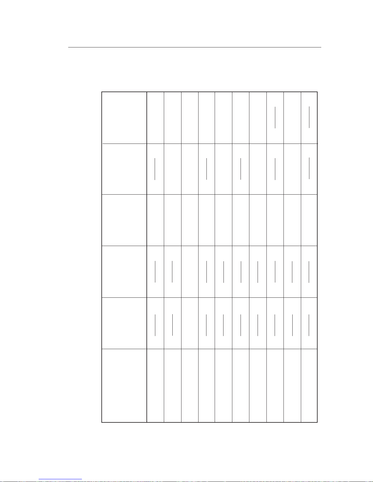
2.9 ENGINE PARAMETER COLOR MARKINGS
ENGINE PARAMETER COLOR MARKINGS ON THE VM 1000 INDICATOR
SECTION 2
LIMITATIONS
Feb 25, 2005
Parameter
RPM ~ U / MIN
0600 - 2700
75 - 245
150 - 435
1300 -1550
24.0 - 28.7
1-50
28.8 - 31.9
32.0
436 - 500
501
0.5 - 8.0
2 -16
17-18
19
13.0 - 29.0
0-24
25-54
55-95
96-97
8.1
98
246
29.1 - 31.0
31.1
2701
MAN PRES ~ HG
OIL PRES ~ PSI
AMPS ~ A
VOLTS ~ V
OIL TEMP ~ °F
CHT ~ °F
EGT ~ °F
FUEL PRES ~ PSI
FUEL FLOW ~ GPH
LOW
RED ARC
(PROHIBITED)
UPPER
RED ARC
(PROHIBITED)
LOW
YELLOW ARC
(CAUTION!)
UPPER
YELLOW ARC
(CAUTION!)
GREEN ARC
(NORMAL
OPERATING
RANGE)
Page 34

SA 160
AIRCRAFTA I R C R A F T
Symphony
2-6
2.11 WEIGHT LIMITS
(a) Maximum Ramp Weight: 975 kg (2150 lbs)
(b) Maximum Takeoff Weight:
For dependence maximum weights on performance see
section 5, “Performance”.
975 kg (2150 lbs)
(c) Maximum Landing Weight 926 kg (2042 lbs)
(d) Maximum Weight in Baggage Compartment 75 kg (165 lbs)
but in the front or rear area maximum 45 kg (99 lbs)
NOTE:
2.13 CENTER OF GRAVITY LIMITS
Weight Forward Aft
kg /lbs (m / in. aft of (m / in. aft of
Datum.) Datum)
648 / 1428 2.45 / 96.46 975 / 2150 - 2.60 / 102.36
hanges between the specified points are linear. The
reference datum is 1.5367 m (60.5 in.) in front of the
firewall. Statements for correct loading see also in
section 6, “Weight and Balance".
NOTE: C
2.15 MANEUVER LIMITS
All aerobatics maneuvers including spins are prohibited.
The aircraft is authorized for maneuvers in which the angle off bank is
notmore than60°.
SECTION 2
LIMITATIONS
Feb 25, 2005
Page 35

SA 160
AIRCRAFTA I R C R A F T
Symphony
2-7
2.17 FLIGHT LOAD FACTOR LIMITS
Configuration Maximum Flight Load
Factor
Flaps Up 3.80 / -1.5
Flaps Down 2.00
Maneuvers with a negative flight load factor are prohibited.
2.21 KINDS OF OPERATIONS
2.19 CREW
SECTION 2
LIMITATIONS
Feb 25, 2005
(a) Minimum Crew VFR 1 Pilot
(b) Minimum Crew IFR
(c) Max. Persons on Board 2
1 Pilot* (FAA registered Aircraft)
* Pilots operating aircraft of other than U.S. registry should refer to the appropriate
regulations of the country of certification.
The aircraft iscertified for VFR Day /Night andIFR operations as long as
theequipment requiredby FARPart91 isinstalled andoperational.
Flightinto knownor forecasticing conditionsis prohibited.
The reference to types of flight operations on the operating limitation
placard reflects equipment installed at the time of Airworthiness
Certificateissuance.
Page 36

SA 160
AIRCRAFTA I R C R A F T
Symphony
2-8
2.23 FUEL LIMITATIONS
2.25 OTHER LIMITATIONS
(a) Total Fuel: 122 l (32.2 U.S.Gallons)
(c) Unusable Fuel: 12 l (3.1 U.S.Gallons)
Additional Fuel Limitations:
(a) With less than 12 liters (3 U.S. Gallons) per each wing tank (Indicator
shows “Lo”) power on descents with flaps fully extended must be
limitedto maximum10 minutesduration.
(b) Usable Fuel: 110 l (29.1 U.S.Gallons)
SECTION 2
LIMITATIONS
(a) Airframe
For safe aircraft operation all four Vortex Generators (Refer to Section
7, 7.3Aircraft) mustbe inplace andin goodcondition.
Absence of one or several Vortex Generators affects the flight
behaviorof theaircraft unfavorablywhen closeto thestall speed.
WARNING !
2.27 TEMPERATURE LIMITATION
(a) OAT for Operating (Avionics) -20/+50°C
Feb 25, 2005
Page 37

SA 160
AIRCRAFTA I R C R A F T
Symphony
2-9
SECTION 2
LIMITATIONS
2.29 PLACARDS
The following placards must be attached inboard and outboard of the
aircraftin therequired places.
1.In fullview ofthe pilot:
WITH FUELBELOW 12 LITERS (3 U.S. GAL.) IN
EACH WING TANK (”Lo” IND.), POWER ON
DESCENTS WITH FLAPS DOWN ARE
LIMITEDTO 10 MINUTESMAX DURATION.
(SEEPOH)
Feb 25, 2005
For IFR
equipped
aircraft
only.
For VFR
equipped
aircraft
only.
OPERATING MODE: NORMAL CATEGORY
FOR FLIGHTS IN VFR, DAY AND NIGHT CERTIFIED
FLIGHTS INTO KNOWN ICING CONDITIONS ARE PROHIBITED!
FLIGHTS IN HEAVY TURBULENT AIR AND
CLOSE TO THUNDERSTORMS ARE PROHIBITED!
SEE THE LIMITATION SECTION IN THE POH
MAXIMUM GROSS WEIGHT:
MANEUVERING SPEED:
MAX. FLAP EXTENDED SPEED:
MAX. DEMONSTRATED CROSSWIND
COMPONENT:
MAXIMUM LANDING WEIGHT:
2150 [lbs]
2042 [lbs]
116 [kts]
90 [kts]
20 [kts]
17 [kts]
TAKEOFF
LANDING
OPERATING MODE: NORMAL CATEGORY
FOR FLIGHTS IN VFR, IFR, DAY AND NIGHT CERTIFIED
FLIGHTS INTO KNOWN ICING CONDITIONS ARE PROHIBITED!
FLIGHTS IN HEAVY TURBULENT AIR AND
CLOSE TO THUNDERSTORMS ARE PROHIBITED!
SEE THE LIMITATION SECTION IN THE POH
MAXIMUM GROSS WEIGHT:
MANEUVERING SPEED:
MAX. FLAP EXTENDED SPEED:
MAX. DEMONSTRATED CROSSWIND
COMPONENT:
MAXIMUM LANDING WEIGHT:
2150 [lbs]
2042 [lbs]
116 [kts]
90 [kts]
20 [kts]
17 [kts]
TAKEOFF
LANDING
Page 38

SA 160
AIRCRAFTA I R C R A F T
Symphony
2-10
SECTION 2
LIMITATIONS
MODEL
A 229
S
MANUFACTURED
SA 160
ERIAL NO.
0X/200X S-XXXX
Symphony Aircraft Industries
Trois-Rivieres-Québec
Canada
2. Near oil access door
3. Left fuselage, near the engine cowling
USE ONLY OIL THAT COMPLIES WITH APPLICABLE
PILOT’S OPERATING HANDBOOK
ENGINE OIL
ABOVE 16°C (60°F) SAE 40 OR SAE 50
-1°C TO 32°C SAE 40
-18°C TO 21°C SAE 30 OR SAE 40
BELOW -12°C SAE 30
(30°F) (90°F)
(0°F) (70°F)
(10°F)
NO SMOKING
THE AIRCRAFT MUST BE OPERATED IN COMPLIANCE WITH THE PILOT’S OPERATING HANDBOOK
ACROBATIC MANEUVERS, INCLUDING SPINS, ARE NOT APPROVED
TYPE CERTIFICATE
Feb 25, 2005
Page 39

SA 160
AIRCRAFTA I R C R A F T
Symphony
2-11
SECTION 2
LIMITATIONS
Rescue!
PUSH AND TURN
DOWN TO OPEN
2. OPEN2. OPEN
1. PUSH
5. On the doors below the door handle
99 LBS MAXIMUM
MAXIMUM
MAXIMUM 165 COMBINED
BAGGAGE FORWARD OF RED MARKING
BAGGAGE AFT OF RED MARKING
99 LBS
LBS
SEE WEIGHT AND BALANCE DATA
6. On the baggage door
AIRCRAFT DATA PLATE
LOCATED AT FIREWALL
THIS SIDE!
4. On the left fuselage side below the horizontal stabilizer
Feb 25, 2005
Page 40
SA 160
AIRCRAFTA I R C R A F T
Symphony
2-12
SECTION 2
LIMITATIONS
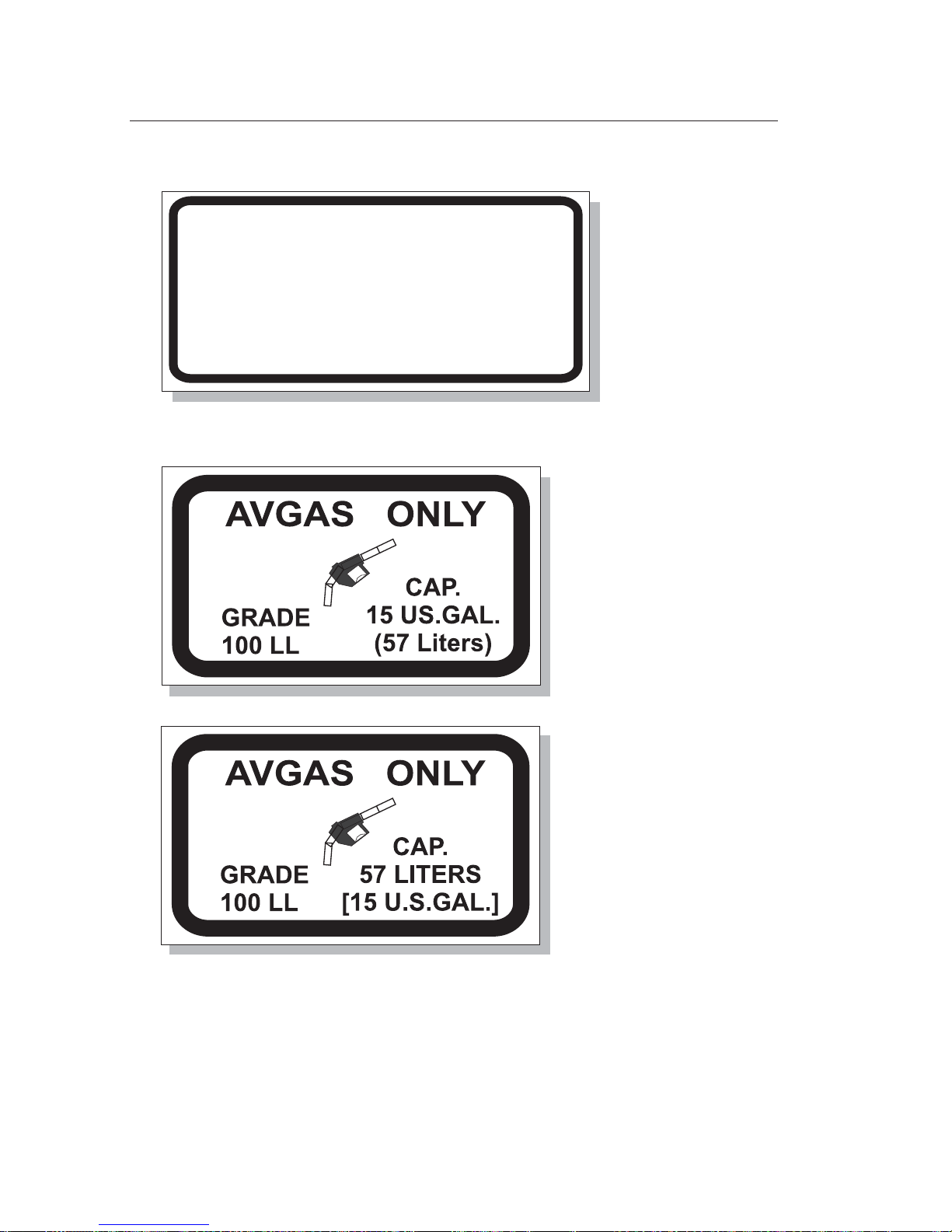
8. Near fuel tank filler cap
CAUTION 24 VOLTS D.C.
OBSERVE PROPER POLARITY
THIS AIRCRAFT IS EQUIPPED WITH
ALTERNATOR AND A NEGATIVE
GROUND SYSTEM.
REVERSE POLARITY WILL DAMAGE
ELECTRICAL COMPONENTS.
7. Near external power receptacle
Feb 25, 2005
For aircraft registered
in countries where SI
units are used.
For aircraft registered
in countries where
imperial units are
used.
Page 41

SA 160
AIRCRAFTA I R C R A F T
Symphony
TABLE OF CONTENTS
SECTION 3
EMERGENCY PROCEDURES
3-1
SECTION 3
EMERGENCY PROCEDURES
Page
3.1 General..................................................................................................3-2
3.3 Airspeeds for Emergency Operations..............................................3-3
3.5 Emergency Procedures Checklist .....................................................3-4
(a) Engine Failure During Takeoff Roll.......................................3-4
(b) Engine Failure Immediately After Takeoff...........................3-4
(c) Engine Failure During Flight (Restart Procedures)............3-4
(d) Landing Without Engine Power............................................3-5
(e) Rough Engine Operation .......................................................3-5
(f) Precautionary Landing With Engine Power........................3-6
(g) Ditching .....................................................................................3-6
(h) Engine Fire During Start.........................................................3-7
(i) Engine Fire In Flight................................................................3-7
(j) Electrical Fire In Flight ............................................................3-8
(k) Loss Of Oil Pressure ................................................................3-8
(l) Power Supply System Malfunction.......................................3-9
(m) Excessive Rate Of Charge.......................................................3-9
(n) Icing............................................................................................3-9
(o) Flap Actuator Drive Failure ...................................................3-9
(p) Static Source Blockage (IFR).................................................3-10
(q) Spin Recovery Procedure .....................................................3-10
3.7 Amplified Emergency Procedures..................................................3-11
Engine Failure During Takeoff Roll (3.5 a)..................................3-11
Engine Failure Immediately After Takeoff (3.5 b)......................3-11
Engine Failure During Flight (3.5 c).............................................3-12
Landing Without Engine Power (3.5 d) ......................................3-13
Rough Engine Operation (3.5 e)...................................................3-14
Feb 25, 2005
Page 42

SA 160
AIRCRAFTA I R C R A F T
Symphony
3-2
TABLE OF CONTENTS (Continued)
3.1 GENERAL
SECTION 3
EMERGENCY PROCEDURES
Precautionary Landing With Engine Power (3.5 f) ...................3-14
Ditching (3.5 g)................................................................................3-15
Engine Fire During Start (3.5 h) ...................................................3-15
Engine Fire In Flight (3.5 i)............................................................3-16
Electrical Fire In Flight (3.5 j) ........................................................3-16
Loss Of Oil Pressure (3.5 k)...........................................................3-17
Power Supply System Malfunction (3.5 l)...................................3-18
Excessive Rate Of Charge (3.5 m).................................................3-18
Icing (3.5 n) ......................................................................................3-19
Static Source Blockage IFR (3.5 p)................................................3-20
Spin Recovery Procedure (3.5 q) ..................................................3-20
This section contains the recommended procedures for coping with
various emergencies or critical situations as required by the Aviation
Authorities, as well as those necessary for operation of the aircraft, as
determined bythe operatingand designfeatures ofthe aircraft.
Emergency procedures associated with optional systems and
equipment, which require handbook supplements, are presented in
Section9, “Supplements”.
Thissection isdivided intotwo mainparts:
1) The first part contains the emergency procedure checklists. These
checklists are clearly arranged to give an action sequence to be
followedduring givensituations withoutexplanations.
2) The second part provides amplified emergency procedures
corresponding tothe emergency procedures checklist items. These
amplified emergency procedures contain additional information to
Feb 25, 2005
Page 43

SA 160
AIRCRAFTA I R C R A F T
Symphony
3-3
3.3 AIRSPEEDS FOR EMERGENCY OPERATIONS
(a) Stalling Speeds
(b) Maneuvering Speeds
(c) Never Exceed Speed
(d) Speed For Maximum Gliding
975 kg (2150 lbs) Flaps Up ............................................................60 KIAS
, Flaps Full Down..............................................51 KIAS
...........................................................................116 KIAS
..................................................................162 KIAS
i) Flaps Up.......................................................................................74 KIAS
ii) Flaps 20°......................................................................................65 KIAS
Gliding at the above speeds will result in 1.6 NM of gliding distance
per 1000 ft for both flight configurations.
975 kg (2150 lbs)
975 kg (2150 lbs)
Distance Without Engine Power
SECTION 3
EMERGENCY PROCEDURES
provide the pilot with a more complete description of the
procedures and a better understanding of the reasons for the
actionslisted.
The numbers located in parentheses () after each paragraph
headingindicate thecorresponding checklistparagraph.
It isrecommended thatpilots familiarizethemselves withthe emergency
procedures described in this section and review them periodically. This
process helps ensure pilots take the appropriate action should an
emergencysituation arise.
These proceduresare offeredas acourse ofaction forcoping witha given
situation or condition.
.
Standard Emergency Procedures are a part of pilot training. The
information given here does not replace this education. They provide a
sourceof referencefor theprocedures thatare applicableto thisaircraft.
They are not a substitute for sound judgment,
goodairmanship andcommon sense
Feb 25, 2005
Page 44

SA 160
AIRCRAFTA I R C R A F T
Symphony
3-4
3.5 EMERGENCY PROCEDURES CHECKLIST
(a) Engine Failure During Takeoff Roll
1. Throttle...........................................................................................IDLE
2. Apply brakesand holddirection. Avoidobstructions, ifpossible:
3. Flaps .......................................................................................RETRACT
4. Mixture ........................................................................IDLE CUT-OFF
5. Ignition Switch ...............................................................................OFF
6. Switch ALT / BAT............................................................................OFF
(b) Engine Failure Immediately After Takeoff
1. Establish glide,
Airspeed with Flaps down .....................................................65 KIAS
Airspeed with Flaps up...........................................................74 KIAS
2. Land straight ahead, make only shallow turn to avoid
obstructions, if possible:
3. Mixture ........................................................................IDLE CUT-OFF
4. Fuel Valve ........................................................................................OFF
5. Ignition Switch ...............................................................................OFF
6. Switch ALT / BAT............................................................................OFF
(c) Engine Failure During Flight (Restart Procedures)
1. Establish glide - secure airspeed of 74 KIAS. Locate suitable
field. At sufficient flight altitude:
2. Mixture................................................................CHECK FULL RICH
3. Aux. Fuel Pump ...............................................................................ON
4. Carburetor Heat...............................................................................ON
5. Ignition Switch ........................................................................“BOTH“
SECTION 3
EMERGENCY PROCEDURES
Feb 25, 2005
Page 45

SA 160
AIRCRAFTA I R C R A F T
Symphony
6. Fuel Valve ..........................................................................CHECK ON
7. Fuel Quantity ...........................................................................CHECK
8. Engine Parameters...................................................................CHECK
9.
If power is not restored, prepare for Landing Without Engine
Power (d).
If propeller is stopped (V<70 KIAS):
Ignition switch shortly ..........................................................“START“
to initiate autorotation.
3-5
SECTION 3
EMERGENCY PROCEDURES
(d) Landing Without Engine Power
1. Airspeed ....................................................................................74 KIAS
2. Seat Belts and Harnesses..........................................................TIGHT
3. Flaps .............................................................................as required SET
Before landing:
4. Mixture ........................................................................IDLE CUT-OFF
5. Fuel Valve ........................................................................................OFF
6. Ignition Switch ...............................................................................OFF
7. Switch ALT / BAT............................................................................OFF
Touchdown with lowest possible airspeed
8. Doors................................UNLATCH PRIOR TO TOUCHDOWN
9. Brakes as required.....................................................................APPLY
(e) Rough Engine Operation
1. Carburetor Heat...............................................................................ON
2. Aux. Fuel Pump ...............................................................................ON
3. Mixture ...........................ADJUST for MAXIMUM SMOOTHNESS
4. Primer ......................................................................CHECK LOCKED
5. Ignition Switch...................................................L thenR; thenBOTH
If operation is satisfactory on either magneto, continue on that
magneto to first suitable airfield.
7. Engine Parameters...................................................................CHECK
If roughness continues for some minutes and atmospheric
conditions make carburetor icing unlikely:
8. Carburetor Heat .............................................................................OFF
Feb 25, 2005
Page 46

SA 160
AIRCRAFTA I R C R A F T
Symphony
3-6
SECTION 3
EMERGENCY PROCEDURES
(f) Precautionary Landing With Engine Power
1. Locate suitablefield. Test suitabilityof thefield withoverflight.
2. If radio contact is available, inform the corresponding ground
stationabout intentionsand location.
3. Prepare forlanding approach. In finalturn:
4. Airspeed ....................................................................................65 KIAS
5. Flaps....................................................................................................40°
6. Seat Belts and Harnesses..........................................................TIGHT
Before landing:
7. Switch ALT / BAT............................................................................OFF
9. After touchdown with lowest possible airspeed, apply brakes
and attempt to avoid obstructions, if possible:
10. Mixture ........................................................................IDLE CUT-OFF
11. Ignition Switch ...............................................................................OFF
12. Fuel Valve ........................................................................................OFF
8. Cabin Doors........................UNLATCH PRIOR TO TOUCHDOWN
(g) Ditching
After an engine failure immediately secure glide speed 74 KIAS, trim
aircraft. Whenthe mainlandcan't bereached:
1. Transmit Mayday message giving location and intentions, set
Squawk7700 (oras directedby TC)
Perform approach into the wind if strong winds and heavy seas,
otherwise parallelto swells.
2. Seat Belts and Harnesses..........................................................TIGHT
3. ELT ........................................................................................ACTIVATE
4. Flaps (65 KIAS) ..................................................................................40°
5.
7. Aircraft ................................................................................EVACUATE
8. Inflate LifeVests andRaft whenclear ofaircraft.
Cabin Doors......................UNLATCH PRIOR TO TOUCHDOWN
6 Touchdown on water surface should be made at lowest possible
airspeed with maximum angle off attack.
Feb 25, 2005
Page 47

SA 160
AIRCRAFTA I R C R A F T
Symphony
3-7
SECTION 3
EMERGENCY PROCEDURES
(h) Engine Fire During Engine Start
1. Ignition Switch........................................................CRANK ENGINE
If engine starts:
2. Keep throttle for a few minutes at.....................................1800 RPM
3. Engine .............................................................................SHUTDOWN
and inspect for damage.
If engine fails to start:
4. Ignition Switch.........................CONTINUE CRANKING ENGINE
5. Throttle .............................................................................FULL OPEN
6. Mixture ........................................................................IDLE CUT-OFF
7. Fuel Valve ........................................................................................OFF
If fire continues
8. “ALT / BAT“......................................................................................OFF
9. Fire Extinguisher ............................................................................USE
10. Aircraft ................................................................................EVACUATE
(i) Engine Fire In Flight
1. Fuel Valve ........................................................................................OFF
2. Throttle....................................................................................CLOSED
3. Mixture ........................................................................IDLE CUT-OFF
4. Aux. Fuel Pump ..............................................................................OFF
5. Cabin Heat.......................................................................................OFF
6. Cabin Ventilation for Lowest
Smoke in Cabin ...............................................................................SET
Inform the corresponding ground station
7. “ALT / BAT“......................................................................................OFF
8. Fire Extinguisher as required............................................ACTIVATE
Proceed with Landing Without Engine Power(d)
Feb 25, 2005
Page 48

SA 160
AIRCRAFTA I R C R A F T
Symphony
3-8
SECTION 3
EMERGENCY PROCEDURES
(j) Electrical Fire In Flight
1. Switch ALT / BAT............................................................................OFF
2. Cabin Ventilation ...................................................................CLOSED
3. Cabin Heat.......................................................................................OFF
4. Fire Extinguisher as required............................................ACTIVATE
5. All other Switches
(except ignition switch).................................................................OFF
Afterfire iscompletely extinguished,ventilate cabin.
If it cannot be visually determined that the fire is completely
extinguished,land assoon aspossible.
Afterascertaining thatfire hasbeen extinguishedcompletely:
6. Cabin ventilation.............................................................FULL OPEN
7. Switch ALT / BAT.............................................................................ON
8. Circuit Breakers........................................................................CHECK
If the short circuit is localized:
9. Required electrics ............................................................................ON
10. Land as soon as practical to inspect damages.
WARNING !
(k) Loss Of Oil Pressure
Land as soon as possible.
Oil Temperature.............................................................................CHECK
Prepare for Landing Without Engine Power (d).
Feb 25, 2005
Page 49

SA 160
AIRCRAFTA I R C R A F T
Symphony
3-9
SECTION 3
EMERGENCY PROCEDURES
(l) Power Supply System Malfunction
Ammeterand voltmetershows apower supplysystem malfunction.
1. “ALT“ Switch .....................................................................CHECK ON
2. ALT FLD circuit breaker..........................................................CHECK
and reset as required.
3. “ALT“ Switch ..................................................................OFF then ON
Ifpower ofalternator isnot restored:
4. “ALT“Switch....................................................................................OFF
5. Non-essential electrical equipment.............................................OFF
6. Land as soon as practical.
(m) Excessive Rate Of Charge
Ammeter and voltmeter shows a excessive rate of charge.
1. “ALT“ Switch ...................................................................................OFF
2. Non-essential electrical equipment.............................................OFF
3. Land as soon as practical.
(n) Icing
Watch for signs of icing conditions, immediately leave the region in
whichthe icingoccurred. Ifpossible, changeflight altitude.
Feb 25, 2005
(o) Flap Actuator Drive Failure
“Flap in Motion” light stay ¨on¨ when the flaps are fully retracted or
extended.
1. FLAPS circuit breaker .......................................................................PULL
2. Land as soon as practical.
Page 50

SA 160
AIRCRAFTA I R C R A F T
Symphony
Page 51

SA 160
AIRCRAFTA I R C R A F T
Symphony
SECTION 3
EMERGENCY PROCEDURES
(q) Spin Recovery Procedure
1. Throttle ..........................................................................................IDLE
2. Ailerons ................................................................................NEUTRAL
3. Rudder ..........FULL OPPOSITE TO DIRECTION OF ROTATION
At the same time
4. Elevator ................................................................................NEUTRAL
5. Rudder (when rotation stops) ..........................................NEUTRAL
As rotation stops make a smooth recovery from the dive. If flaps
were extended, retract and establish horizontal flight with engine
poweras required.
3-10
Icing has a very strong negative effect on the aerodynamic
characteristicsof theaircraft. Stalling speedincreases.
Continuedflight inicing conditionsis prohibited.
1. Pitot Heat Switch.............................................................................ON
2. Carburetor Heat...............................................................................ON
3.
4. Wind shield Heat
With an ice accumulation of 5mm ore more on the wing leading
edges, perform landing with flaps retracted or in 20° position.
Airspeed in final approach must be higher corresponding the ice
accumulationand theflap position.
Cabin Heat / Ventilation .................................................................ON
Land at the nearest airfield.
.............................................................................ON
(p) Static Source Blockage (IFR)
1. Alternate Static Source ....................................................................OPEN
2. Airspeed .........................................................................................ADJUST
According to the Airspeed Calibration
(Alternate Static Source) table in Section 5. P.5.11
WARNING !
Feb 25, 2005
Page 52

SA 160
AIRCRAFTA I R C R A F T
Symphony
SECTION 3
EMERGENCY PROCEDURES
3.7 AMPLIFIED EMERGENCY PROCEDURES
Engine Failure During Takeoff Roll Checklist 3.5 a
If lossof poweroccurs duringtakeoff roll, theaircraft mustbe brought
to a halt as soon as possible in order to avoid leaving the runway.
Enginepower mustbe reducedto idle.
It is recommended that flaps be retracted in order to reduce lift force.
This increases the rolling friction and therefore decreases the
accelerate-stopdistance.
If the aircraft goes off the runway, damage (possible collision with
obstacles and even overturning) cannot be excluded. Seat belts and
harnesses mustbe tightto reducethe possibilityof injury.
In order to reduce the danger of a short circuit and /or fire, the fuel
supply tothe engineshould becut offand theelectrical systemturned
off. Cut off the fuel supply by moving the Mixture control to the
position IDLE CUT-OFF. Turn off the ALT / BAT switch and the
ignitionswitch.
Engine Failure Immediately After Takeoff Checklist 3.5 b
In climbingflight withoutengine power, theaircraft will loseairspeed
very quickly. In order to guarantee further controllability the control
stickmust bemoved forward toestablish aglide attitude.
Avoidobstacles andavoid steepangles ofbank.
At no time should the airspeed decrease below the stalling speed
for the configuration setting. Note: This speed increases by
increasing the angle of bank of the aircraft. See section 5 Fig. 5-5
"StallingSpeed".
WARNING !
Feb 25, 2005
3-11
Page 53

SA 160
AIRCRAFTA I R C R A F T
Symphony
3-12
Engine Failure During Flight (Restart Procedures)
Checklist 3.5 c
Sudden and complete engine power loss is usually the result of fuel
flow interruption. Power should be restored shortly after fuel flowis
restored.
If power loss occurs at low altitude, the first step is to prepare for an
emergency landing. Promptly establish a glide attitude and secure
the speed for best gliding angle (74 KIAS). Trim the aircraft and look
fora fieldsuitable forlanding.
If altitude permits, move the mixture control to RICH and check the
auxiliary fuel pump and, if required, switch to ON. It supports the
fuel supply to the engine if the engine driven fuel pump has failed.
Switch the carburetor heat to ON. Check to ensure the ignition
switchis in"BOTH" position.
At airspeeds below 75 KIAS the propeller can stop (no
autorotation).
In this event increase the airspeed to autorotation or turn ignition
When performing an off field landing, damage (possible collision
with obstacles and even overturning) cannot be excluded. Seat belts
andharnesses mustbe tightto reducethe possibilityof injury.
In order to reduce the danger of a short circuit and /or fire, the fuel
supply to the engine should cut off and the electrical system turned
off. Cut off the fuel supply by moving the Mixture control to the
position IDLECUT-OFF and the fuel valve to OFF. Turn off the ALT /
BATswitch andthe ignitionswitch.
Touchdownshould bemade atthe lowestpossible airspeed.
WARNING !
Feb 25, 2005
SECTION 3
EMERGENCY PROCEDURES
Page 54

SA 160
AIRCRAFTA I R C R A F T
Symphony
Page 55

SA 160
AIRCRAFTA I R C R A F T
Symphony
3-13
SECTION 3
EMERGENCY PROCEDURES
Landing Without Engine Power Checklist 3.5 d
The gliding air speed of 74 KIAS (flaps up) and 65 KIAS (flaps 20°)
delivers minimum loss of altitude in a given time. Over a distance of
1.6NM theloss ofaltitude is1000 ft.
With sufficient altitude and after selection of a suitable field, a spiral
pattern should be attempted around the selected field. In this way, a
series of correction possibilities are available in order to complete a
preciselanding atthe chosenpoint withoutengine power.
While descending, if radio contact is available, notify the
corresponding ground station of your difficulty, location and
intentions. Excessaltitude maybe lostby wideningthe pattern, using
flaps,side-slipping, ora combinationof these.
Atno time should theairspeed reducebelow thestalling speed for
the configuration setting. Note: This speed increases by
increasing the angle of bank of the aircraft. See section 5, Fig. 5-4
“StallingSpeed“.
In order to contact the ground at the lowest possible speed, flaps
should be full extended just before landing and the speed should be
65KIAS.
WARNING !
switchto STARTtostart theengine.
Check the fuel valve is in ON position, and the fuel quantity in the
wing tanks is sufficient. By examining the engine parameters, it is
usually possible to determine the cause of the power loss and rectify
thesituation.
As soon as the engine power is restored, and if the failure cause was
notcarburetor icing,move thecarburetor heatto theOFF position.
If power is not regained, proceed with the “Landing Without Engine
Feb 25, 2005
Page 56

SA 160
AIRCRAFTA I R C R A F T
Symphony
Precautionary Landing With Engine Power Checklist 3.5 f
A precautionary landing with engine power usually offers sufficient
time reserve to take all the necessary measures to minimize the
danger. The choice of the field should be made considering size,
surface conditions, vegetation, any obstructions in the planned
3-14
Rough Engine Operation Checklist 3.5 e
Roughengine operationcan becaused byvarious problems.
In the case of carburetor icing, turn carburetor heat ON. Wait for a
decrease in engine roughness or an increase in RPM, indicating ice
removal. If carburetor heat shows no effect, and atmospheric
conditions make carburetor icing unlikely (if CAT indicator installed,
check reading), after some minutes turn carburetor heat OFF. Check
thefuel valveis inON position.
The auxiliary fuel pump supports the fuel supply to engine if the
enginedriven fuelpump doesnot workcorrectly.
Check the mixture control lever position, adjust for maximum
smoothness. A unlocked primer may also cause for engine
roughness.
Switching from BOTH to either L or R ignition switch position will
identifya magnetoor aspark plugproblem.
Check the VM 1000 display for abnormal readings that may indicate
thecause.
SECTION 3
EMERGENCY PROCEDURES
While perform a forced landing on unknown field, damage (possible
collision with obstacles and even overturning) cannot be excluded.
Seat belts and harnesses must be tight to reduce the possibility of
injury.
In order to reduce the danger of a short circuit and /or fire, the fuel
supply to the engine should cut off and the electrical system turned
off. Cut off the fuel supply by moving the Mixture control to the
position IDLECUT-OFF and the fuel valve to OFF. Turn off the ALT /
BATswitch andthe ignitionswitch.
Feb 25, 2005
Page 57

SA 160
AIRCRAFTA I R C R A F T
Symphony
3-15
SECTION 3
EMERGENCY PROCEDURES
approach direction and the current wind direction. A fly-over
provides the opportunity for abetter assessment of the selectedfield.
A ground station by radio should if possible, be informed of the
decisionfor precautionary landingand thelocation.
It is recommended to make a landing approach from the downwind
leg above the field. This procedure provides enough time and
correction possibilitiesfor a precise approach. On final approach the
normal speedand flapsettings shouldbe taken.
Perform a landing on an non-prepared field, any damage (possible
collision with obstacles or overturn) can not be excluded. Seat belts
andharnesses setup tightlyreduce theinjury hazard.
When committed toa landing, turn OFF theALT / BAT switchbefore
touchdown and unlatch both doors before touch down. After
touchdown at the lowest possible airspeed, attempt to brake the
aircraft as soonas possible. Stop the engine withmixture controland
Ignition Switch. Then, closing the fuel valve, interrupt the fuel
supply.
Ditching Checklist 3.5 g
During a landing in water, tighten seat belts to reduce the risk of
injury. Brief passenger, if any, on the opening mechanism of the seat
beltsbefore touchdown.Unlatchdoor beforetouchdown.
Touchdown on the water surface with minimum possible airspeed
and maximum angle of attack. Evacuate aircraft, inflate life vests and
raftwhen clearof aircraft.
Engine Fire During Engine Start Checklist 3.5 h
Engine firesduring enginestart are usuallythe result ofover priming.
In such a case, the first effort to extinguish the fire should be to
Feb 25, 2005
Page 58

SA 160
AIRCRAFTA I R C R A F T
Symphony
3-16
Electrical Fire In Flight Checklist 3.5 j
If smoke and/or fumes are experienced inthe cabin, this may indicate
a cable fire, the whole electrical system of the aircraft should be
switched off to prevent spreading of any fire: With the exception of
the ignition, turn all electrical equipment and the ALT / BAT switch
OFF.
Turn the cabin heat OFF and close the cabin ventilation to avoid
smokeingress intothe cabin.
After discharging fire extinguisher ascertain that the fire has been
extinguished. Then ventilatethe cabinsufficiently.
SECTION 3
EMERGENCY PROCEDURES
attempt an engine start in order to draw the excess fuel back into the
induction system. If the engine starts, with higher RPM there is a
good chance to blow out a possible external fire. If the engine fails to
start, try to draw the fire back into the engine by moving the mixture
control to IDLE CUT-OFF, opening the throttle, turning OFF the fuel
valve,while crankingthe engine.
If is not possible to extinguish thefire, turn OFF the ALT / BAT switch,
usethe fireextinguisher,evacuate theaircraft.
Engine Fire In Flight Checklist 3.5 i
If an enginefire exists, shut off thefuel supplyto theengine by
closing the fuel valve. Then, stop the engine with the throttle, the
mixture control and the ignition switch. Turn OFF the auxiliary fuel
pump.
In order to avoid smoke reaching the cabin, check cabin heat is off. If
smoke enters the cabin via cabin ventilation, close it. After
information of the corresponding groundstation about thesituation,
turn OFF ALT/ BAT switch. Proceed with the “Landing Without
EnginePower” procedure(Checklist 3.5d).
clearly
Feb 25, 2005
Page 59

SA 160
AIRCRAFTA I R C R A F T
Symphony
3-17
WARNING !
Loss of Oil Pressure Checklist 3.5 k
Loss of oil pressuremay beeither partialor complete. A partial lossof
oil pressure usually indicates a malfunction in the oil pressure
regulating systemof theengine. However,an oilloss and/ordefect of
the oilpump isalso possible. In eithercase, a landingshould bemade
as soon as possible to investigate the cause and to prevent engine
damage.
A complete loss of oil pressure indication may be the result of a faulty
gauge,a totaloil pumpfailure, ormay signifyoil exhaustion.
Immediately proceedtoward the nearestairfield, andbe prepared for
the engine to stop suddenly. Avoid unnecessary loadson the engine.
Flight altitude should be maintained. Pay particular attention to the
oiltemperature.
Depending on the circumstances, it may be advisable to make a off
field landing while power is still available, particularly if other
indications of actual oil pressure loss, such as sudden increase in
temperatures, or oil smoke, or oil on the windshield, are apparent,
andan airfield isnot close.
If an engine stoppage occurs, proceed with “Landing Without
EnginePower” (Checklist3.5 d)
SECTION 3
EMERGENCY PROCEDURES
Feb 25, 2005
Residual smoke in the cabin can cause feeling of sickness and of
nausea. Therefore, ventilatecabin fully andmake aprecautionary
emergencylanding.
Pop all circuit breakers and set ALT / BAT switch ON. Then set circuit
breakers one by one for required electrics and to localize a possible
shortcircuit.
Page 60

SA 160
AIRCRAFTA I R C R A F T
Symphony
3-18
SECTION 3
EMERGENCY PROCEDURES
Power Supply System Malfunction Checklist 3.5 l
Loss of alternator output can be detected by monitoring the ammeter
andthe voltmeteron theVM 1000indicator.
Verify the “ALT” switch is on. Check the ALT FLD circuit breaker and
resetif required.
Attempt to reset the over voltage protection system of the alternator
regulator by turning “ALT” OFF and then ON. Check the ammeter
andvoltmeter.
If the alternator will not reset, turn OFF the ALT switch and reduce
the electrical load to a minimum. All electrical load is now being
supplied by the battery. Turn off all non-essential electrical
equipment.
Proceedtoward nearestairfield.
A power supply malfunction has no effect of the engine
operation.
NOTE:
Excessive Rate Of Charge Checklist 3.5 m
With a faulty alternator regulator an excessive rate of charge and an
overchargingof thebattery mayoccur.
Electricalequipment maybe damagedby overvoltage.
If ammeter and voltmeter on the VM 1000 indicator indicates an
excessive rate of charge, turn OFF the Alternator by the switch ALT.
Turn off non-essential electrical equipment, to decreases the battery
discharge. In such case all electrical load is being supplied by the
battery. Terminate flightas soonas practical.
Feb 25, 2005
Page 61

SA 160
AIRCRAFTA I R C R A F T
Symphony
3-19
WARNING !
SECTION 3
EMERGENCY PROCEDURES
Feb 25, 2005
Icing Checklist 3.5 n
Under certain circumstances, usually in cold weather, icing
conditions mayprevail andice can accumulateon external surfaces of
the aircraft. The occurrence and the manner of icing depends on the
air temperature, humidity, as well asother atmospherically condition
butalso onthe airspeedof theaircraft.
At the first sign of icing conditions the area of icing should be left as
soonas possible.
Icing has a very strong negative effect on the aerodynamic
characteristicsof theaircraft. Stalling speedincreases.
Continuedflight inicing conditionsis prohibited.
Achange oftemperature willoccur witha changeof altitude.
The pitot heat reduces the chance of ice accumulation on the pitot
tube, which could cause wrong indications and failure of the static /
dynamicsystem.
The carburetor is especially at risk because of the rapid absorption of
heat from the air by vaporization of the fuel. To prevent carburetor
icing and an engine power loss, switch carburetor heat . Cabin
heatingand cabinventilation preventsicing onthe windshield.
It is advisable to proceed toward the nearest airfield and wait for
better weatherconditions.
Withan ice accumulation on the wingleading edges of 5mm or more,
perform alanding withflaps upor in20° position.
The landing approach speed should be higher depending upon
amountof theaccumulation.
ON
Page 62
SA 160
AIRCRAFTA I R C R A F T
Symphony
3-20
SECTION 3
EMERGENCY PROCEDURES
Static Source Blockage (IFR) Checklist 3.5
If erroneous readings of the static source instruments (aispeed, altimeter
and verticalspeed) aresuspected, thealternate staticsource valve, onthe
left side of instrument panel, should be opened to supply static pressure
from the cabin to these instruments. With the alternate static source on,
adjust indicated airspeed slightly during climb or approach according to
the Airspeed Calibration (Alternate Static Source) table in section 5 as
page 5.11 appropriate for vent configuration, causing the aircraft to be
flownwithin thenormal operatingspeed limits.
Spin Recovery Procedure Checklist 3.5 p
Cause ofinadvertent spinsis usually theresult ofheavy orinsensitive
controlinputs. The spinrecoveryis unproblematicwith theSA 160.
Once the spin is recognized: first move the throttle to idle and the
ailerons to neutral. Stop the rotation of the aircraft by applying the
rudder full opposite to the direction of yaw. At the same time move
the control stick forward up until the elevator is approx. in neutral
position,to reducethe angleof attackto subcritical values.
When the rotation stops, neutralize the rudder and make a smooth
recovery from the resulting dive increasing engine power as
required.
Ifflaps weredown retractas soonas rotationis stopped.
For spinrecovery movethe ailerons in neutral position andNOTE:
WARNING !
Feb 25, 2005
Intentionalspins inthe SA 160 are prohibited.
Page 63

SA 160
AIRCRAFTA I R C R A F T
Symphony
check this by means of control stick position to the panel.
Different aileron forces cause an incorrect neutral position
andmay delaythe spinrecovery.
The maximum altitude loss for a 1-turn spin is 300 ft. 1000 ft may
required to accomplishing both, the spin recovery and the dive
3-21
SECTION 3
EMERGENCY PROCEDURES
Feb 25, 2005
Page 64

SA 160
AIRCRAFTA I R C R A F T
Symphony
Page 65

SA 160
AIRCRAFTA I R C R A F T
Symphony
TABLE OF CONTENTS
SECTION 4
NORMAL PROCEDURES
4-1
Page
4.1 General..................................................................................................4-3
4.3 Airspeeds For Normal Operation .....................................................4-4
4.5 Normal Procedures Checklist............................................................4-4
(a) Preflight Inspection .................................................................4-4
(b) Before Starting Engine ............................................................4-9
(c) Starting Engine.........................................................................4-9
(d) Starting Hot Engine ..............................................................4-10
(e) Engine Start With External Power Source .........................4-10
(f) Warm-Up.................................................................................4-10
(g) Taxiing......................................................................................4-11
(h) Ground Check........................................................................4-11
(i) Before Takeoff .........................................................................4-12
(j) Takeoff......................................................................................4-12
Normal Conditions .............................................................4-12
Short Field ............................................................................4-13
(k) Climb........................................................................................4-13
(l) Cruise.......................................................................................4-13
(m) Descent ....................................................................................4-14
(n) Before Landing.......................................................................4-14
(o) Landing....................................................................................4-15
Normal Conditions .............................................................4-15
Balked Landing ...................................................................4-15
(p) After Landing..........................................................................4-15
(q) Engine Shut Down 4-16
(r) After Engine Shut Down ......................................................4-16
SECTION 4
NORMAL PROCEDURES
Feb 25, 2005
Page 66

SA 160
AIRCRAFTA I R C R A F T
Symphony
4-2
TABLE OF CONTENTS (Continued)
Page
4.7 Amplified Normal Procedures ........................................................4-17
(a) Preflight Inspection (4.5 a)....................................................4-17
Cabin .....................................................................................4-17
Left Wing..............................................................................4-18
Nose Section.........................................................................4-19
Right Wing ...........................................................................4-19
Fuselage ................................................................................4-20
(b) Before Starting Engine (4.5 b) ..............................................4-21
(c) Starting Cold Engine (4.5c)...................................................4-22
(d) Starting Hot Engine (4.5d)....................................................4-23
(e) Engine Start with External Power Source..........................4-23
(f) Warm-Up (4.5f).......................................................................4-24
(g) Taxiing (4.5 g) ..........................................................................4-24
(h) Ground Check(4.5h)..............................................................4-25
(i) Before Takeoff (4.5i) ...............................................................4-26
(j) Takeoff (4.5j)............................................................................4-26
Normal Conditions .............................................................4-26
Short Runway......................................................................4-27
(k) Climb (4.5k) .............................................................................4-27
(l) Cruise (4.5l) .............................................................................4-28
(m) Descent (4.5m) ........................................................................4-29
(n) Before Landing (4.5n)............................................................4-30
(o) Landing (4.5o).........................................................................4-31
Normal Conditions .............................................................4-31
Balked Landing ...................................................................4-31
(p) After Landing (4.5p) ..............................................................4-32
(q) Engine Shut Down (4.5q)......................................................4-32
(r) After Engine Shut Down (4.5r) ............................................4-32
SECTION 4
NORMAL PROCEDURES
Feb 25, 2005
Page 67

SA 160
AIRCRAFTA I R C R A F T
Symphony
4-3
4.1 GENERAL
Thissection containsthe normal operatingprocedures forthe aircraft.
All of the normal operating procedures required by the Aviation
Authorities, as well as those necessary for operation of the aircraft, as
determined by the operating and design features of the aircraft, are
presented.
Normal operating procedures associated with optional systems and
equipment, which require handbook supplements, are presented in
Section9, “Supplements”.
This section shouldput the pilotin a position to usethe aircraft and/orits
systems and equipment optimally and safely. Therefore, it is
recommended tomake yourself familiarwith theprocedures and beable
tomaster them.
Thissection isdivided intotwo mainparts:
1. The first part contains the normal procedure checklists. These
checklists are clearly arranged to give an action sequence for normal
procedureswith littleemphasis onthe operationof thesystems.
2. The second part provides amplified normal procedures corresponding to the normal procedures checklist items. These amplified
normal procedures contain detailed information and explanations of
theprocedures andhow toperform them.
Thisportion ofthe sectionis notintended foruse inflight.
The numbers located in parentheses () after each paragraph heading
indicatethe corresponding checklistparagraph.
SECTION 4
NORMAL PROCEDURES
Feb 25, 2005
Page 68

SA 160
AIRCRAFTA I R C R A F T
Symphony
4-4
4.3 AIR SPEEDS FOR NORMAL OPERATION
The following air speeds are important for the safe operation of the
aircraft. These air speeds apply to a standard aircraft up to maximum
weightand understandard conditionsat sealevel.
Performance for a specific aircraft may vary from published values
depending upon different condition; e.g: different equipment on the
aircraft,another engine, andother atmosphericfactors etc.
(a) BestRate ofClimb Speed ............................................................80KIAS
(decreaseofone knotper 1000ft tomin. 73KIAS)
(b) Best Angleof ClimbSpeed..........................................................70 KIAS
(c) Final ApproachSpeed (Flaps40°) ..............................................65KIAS
(d) BalkedLanding............................................................................65 KIAS
(e) MaximumTurbulent AirOperating Speed ............................130KIAS
(f) Max.Demonstr. CrosswindVelocity Takeoff/Ldg. .................20/17kts
4.5 NORMAL PROCEDURES CHECKLIST
SECTION 4
NORMAL PROCEDURES
(a) Preflight Inspection
1. Cabin
Control Stick Lock .....................................................................UNLOCK
POH / Checklists ....................................................................AVAILABLE
Electrical Switches................................................................................OFF
Light Dimmer Switches ......................................................................OFF
Ignition Switch .....................................................................................OFF
Circuit Breakers........................................................................CHECK IN
Throttle..........................................................................................CLOSED
Mixture ..............................................................................IDLE CUT-OFF
Flight Controls ....................................................................CHECK FREE
Trim.....................................................................CHECK, SET NEUTRAL
Feb 25, 2005
Page 69
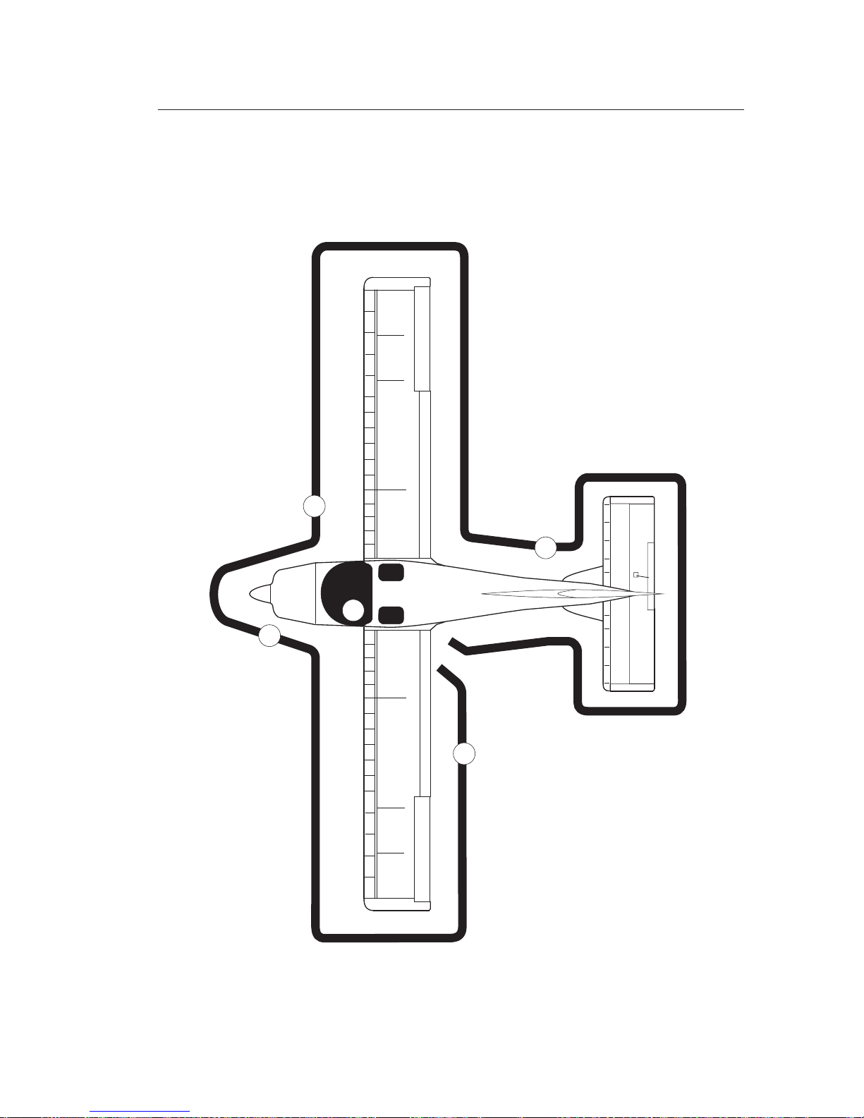
SA 160
AIRCRAFTA I R C R A F T
Symphony
4-5
1
2
3
4
5
Figure 4-1
PREFLIGHT INSPECTION
SECTION 4
NORMAL PROCEDURES
Feb 25, 2005
Page 70

SA 160
AIRCRAFTA I R C R A F T
Symphony
4-6
SECTION 4
NORMAL PROCEDURES
Seat position...................................................................................CHECK
BAT Switch.............................................................................................ON
Fuel Quantity.................................................................................CHECK
Flaps EXTEND, Yellow Light “Flaps in Motion”......................CHECK
Landing Light (at Night)..............................................................CHECK
Strobe Light (at Night)..................................................................CHECK
NAV Light (at Night) ....................................................................CHECK
Instr. / Map Lights (at Night) .......................................................CHECK
BAT Switch............................................................................................OFF
Fuel Tank Sump .............................................DRAIN fuel into clear cup
Fuel ................................................................................CHECK for water,
sediment and proper fuel
Left Main Gear Strut and Wheel Fairing...................................CHECK
Main Wheel Tire............................................................................CHECK
for proper inflation and general condition
Wing Surface .............................................FREE of ICE, FROST, SNOW
Left-Side Top-Deck Hatch.......................................CHECK for security
Flap and Aileron......................................................CHECK for freedom
of movement and security
Bonding Straps ...............................CHECK for security of attachment
and general conditions
Static Dischargers ...........................CHECK for security of attachment
and general conditions
Counter Weight ..............................CHECK for security of attachment
Wing Tip and Lights .....................................................................CHECK
Wing Leading Edge with Vortex Generators ............................CHECK
Stall Warning System....................................................................CHECK
Fuel Tank Vent Line ..........................................CHECK for free venting
2. Left Wing
20° Flap Position Color Marking on Flap Track ........................CHECK
for condition
Feb 25, 2005
Page 71

SA 160
AIRCRAFTA I R C R A F T
Symphony
4-7
SECTION 4
NORMAL PROCEDURES
Pitot Tube........................................................REMOVE pitot tube cover
Pitot Tube Hole.....................................................................CHECK clear
Fuel Tank ....................................................................CHECK VISUALLY
for desired level
Fuel Filler Cap ................................................................................CHECK
secure and vent unobstructed
Cowling...........................................................................................CHECK
fasteners for security
Windshield ........................................................CHECK for any damage
Air Inlets.............................................................CHECK for obstructions
Landing Light ........................................................CHECK for condition
Propeller and Spinner ..............................CHECK for nicks and cracks
Generator Drive Belt.......................................................CHECK tension
Oil...........................................................................................CHECK level
Oil Filler Cup...................................................................................CLOSE
Oil Access Door...............................................................................CLOSE
Nose Gear Strut and Wheel Fairing ...........................................CHECK
Nose Wheel Tire CHECK
For proper inflation and general condition
Wing Surface .............................................FREE of ICE, FROST, SNOW
Fuel Tank ....................................................................CHECK VISUALLY
for desired level
Fuel Filler Cap ................................................................................CHECK
Secure and Vent unobstructed
Wing Leading Edge with Vortex Generators ............................CHECK
Fuel Tank Vent Line ..........................................CHECK for free venting
Wing Tip and Lights .....................................................................CHECK
Counter Weight ..............................CHECK for security of attachment
3. Nose
4. Right Wing
Feb 25, 2005
Page 72

SA 160
AIRCRAFTA I R C R A F T
Symphony
4-8
SECTION 4
NORMAL PROCEDURES
Static Dischargers ...........................CHECK for security of attachment
and general conditions
Flap and Aileron......................................................CHECK for freedom
of movement and security
Bonding Straps ...............................CHECK for security of attachment
and general conditions
Right-Side Top-Deck Hatch ....................................CHECK for security
Fuel Tank Sump .............................................DRAIN fuel into clear cup
Fuel ................................................................................CHECK for water,
sediment and proper fuel
Right Main Gear Strut and Wheel Fairing ................................CHECK
Main Wheel Tire............................................................................CHECK
for proper inflation and general condition
Fuselage Skins ..........................CHECK
Antennas.........................................................................................CHECK
Empennage ............................................CLEAR of ICE, FROST, SNOW
Elevator.....................CHECK for freedom of movement and security
Trim Tab ....................................................................CHECK for integrity
Rudder ......................CHECK for freedom of movement and security
Static Dischargers ...........................CHECK for security of attachment
and general conditions
Baggage Compartment ...................CHECK baggage anchored down
Baggage Door ..................................................CLOSED AND LOCKED
At fuselage bottom:
Fuel System Low-Point Drain......................DRAIN fuel into clear cup
Fuel..................................CHECK for water,
Static/Dynamic System Drain Valve..........................CHECK for water
Cabin:
20° Flap Position Color Marking on Flap Track ........................CHECK
for condition
for stress cracks and fractures
sediment and proper fuel
BAT Switch.............................................................................................ON
5. Fuselage
Feb 25, 2005
Page 73

SA 160
AIRCRAFTA I R C R A F T
Symphony
4-9
SECTION 4
NORMAL PROCEDURES
Feb 25, 2005
(b) Before Starting Engine
Preflight Check ......................................................................COMPLETE
BAT switch..............................................................................................ON
Cabin Lighting (at Night)................................................AS REQUIRED
Fuel Quantity........................................................................SUFFICIENT
Seat Belts and Harnesses........................................FASTENED/CHECK
Cabin Doors ...........................................................CLOSED / LATCHED
Charts, Navigation Equipment, and
Flashlight (at Night) ..............................................................ON BOARD
AVIONIC 1, AVIONIC 2 (IFR) Switches...........................................OFF
Fuel Valve ................................................................................CHECK ON
(c) Starting Cold Engine
Brakes......................................................................................................SET
ALT Switch ............................................................................................ON
INST LT / MAP LT Dimmer Switches (at Night) ..............................ON
DOME LT Switch (at Night)...............................................................OFF
STROBE LT Switch ...............................................................................ON
Carburetor Heat ...................................................................................OFF
Throttle.....................................................................6 mm (1/4 in.) OPEN
Mixture.....................................................................................FULL RICH
Primer ......................................................... ONE TO THREE STROKES
Propeller Area .................................................................................CLEAR
Ignition Switch.................................................................................START
Throttle...........................................................................................ADJUST
to 1000 - 1200 RPM
Oil pressure ....................................................................................CHECK
NAV LT Switch (at Night)....................................................................ON
Flaps.............................................................................................RETRACT
BAT Switch............................................................................................OFF
Page 74

SA 160
AIRCRAFTA I R C R A F T
Symphony
4-10
SECTION 4
NORMAL PROCEDURES
(d) Starting Hot Engine
Brakes......................................................................................................SET
ALT Switch.............................................................................................ON
STROBE LT Switch ...............................................................................ON
Carburetor Heat ...................................................................................OFF
Throttle.....................................................................6 mm (1/4 in.) OPEN
Mixture.....................................................................................FULL RICH
Propeller Area .................................................................................CLEAR
Ignition Switch.................................................................................START
Throttle...........................................................................................ADJUST
to 1000 - 1200 RPM
Oil pressure ....................................................................................CHECK
NAV LT Switch (at Night)....................................................................ON
(e) Engine Start With External Power Source
External Power Source ...........................................................CONNECT
Start engine according (b) and (c) or (b) and (d), then:
Throttle.................................................................................................IDLE
External Power Plug.........................................................DISCONNECT
Throttle...........................................................................................ADJUST
to 1000 - 1200 RPM
Ammeter .........................................................................................CHECK
If engine does not start within 10 sec., disengage the
starter and try again after a few seconds.
NOTE!
(f) Warm-Up
Throttle.............................................................................1000 - 1200 RPM
Avionic Equipment ..................................................ON AS REQUIRED
Feb 25, 2005
Page 75

SA 160
AIRCRAFTA I R C R A F T
Symphony
4-11
SECTION 4
NORMAL PROCEDURES
(g) Taxiing
Taxi Area...........................................................................................CLEAR
Throttle............................................................................APPLY SLOWLY
Brakes ..............................................................................................CHECK
Controls...................................CHECK for free and correct movement
(h) Ground Check
Brakes................................................................................................APPLY
Throttle........................................................................................1800 RPM
Magnetos..................................................................CHECK “L“ then “R“
Maximum Drop 175 RPM
Maximum Difference 50 RPM between magneto
Ignition Switch..............................................................................“BOTH“
Throttle.................................................................................................IDLE
Engine runs smooth with..................................................500 - 700 RPM
Throttle.............................................................................1000 - 1200 RPM
Voltage.............................................................................................CHECK
Oil Pressure ....................................................................................CHECK
Oil Temperature.............................................................................CHECK
Fuel Pressure ..................................................................................CHECK
Carburetor Heat ....................................................................................ON
RPM drop at least 50 RPM
Carburetor Heat ...................................................................................OFF
Feb 25, 2005
Vacuum ...........................................................................................CHECK
Ammeter .........................................................................................CHECK
Oil Temperature.............................................................................CHECK
Circuit Breakers .............................................................................CHECK
Page 76

SA 160
AIRCRAFTA I R C R A F T
Symphony
4-12
SECTION 4
NORMAL PROCEDURES
(j) Takeoff
Normal Conditions
Flaps..........................................................................................................20°
Brakes...........................................................................................RELEASE
Throttle...................................................................................FULL OPEN
At a speed of 53 KIAS..................................................ROTATE to lift-off
After lift-off accelerate to:
Airspeed...................................................................................65 - 75 KIAS
After an altitude of 50 ft is achieved:
(i) Before Takeoff
Brakes................................................................................................APPLY
Throttle.............................................................................1000 - 1200 RPM
Seats ...........................................................................................ENGAGED
Seat Belts and Harnesses........................................FASTENED/CHECK
Empty Seat ...........................................Seat Belts SNUGLY FASTENED
Cabin Doors...................................................CLOSED AND LATCHED
Instrument/Map Light (at Night)...............................................ADJUST
Primer
Fuel Valve ................................................................................CHECK ON
Pitot Heat................................................................................................ON
Aux. Fuel Pump.....................................................................................ON
Fuel Quantity.................................................................................CHECK
Mixture.....................................................................................FULL RICH
Carburetor Heat ...................................................................................OFF
Ignition Switch..............................................................................“BOTH“
Engine Parameters.........................................................................CHECK
Flight Instruments.....................................................adjust and CHECK
Navigation Equipment.............................OPERATIONAL as required
Trim .........................................................................................................SET
...........................................................................................LOCKED
Feb 25, 2005
Page 77

SA 160
AIRCRAFTA I R C R A F T
Symphony
4-13
SECTION 4
NORMAL PROCEDURES
(l) Cruise
Trim .........................................................................................................SET
Cruise Power....................in accordance with the flight planning SET
Feb 25, 2005
Wing Flaps..................................................................................RETRACT
Airspeed ..........................................................................................80 KIAS
Flaps..........................................................................................................20°
Brakes................................................................................................APPLY
Throttle...................................................................................FULL OPEN
When full engine power is available:
Brakes...........................................................................................RELEASE
At a speed of 53 KIAS..................................................ROTATE to lift-off
After lift-off accelerate to:
Airspeed ..........................................................................................62 KIAS
After an altitude of 50 ft is achieved:
Wing Flaps..................................................................................RETRACT
Airspeed ..........................................................................................80 KIAS
Short Field
(k) Climb
Flaps .......................................................................................RETRACTED
Trim .................................................................................................ADJUST
Best Rate Climb Speed..................................................................80 KIAS
Best Angle Climb Speed ...............................................................70 KIAS
Aux. Fuel Pump....................................................................................OFF
Engine Parameters.........................................................................CHECK
Page 78

SA 160
AIRCRAFTA I R C R A F T
Symphony
CAUTION !
4-14
SECTION 4
NORMAL PROCEDURES
(n) Before Landing
SeatBelts andHarnesses.........................................FASTENED/CHECK
Mixture.....................................................................................FULL RICH
Aux. Fuel Pump.....................................................................................ON
Carburetor Heat ....................................................................................ON
Landing Light........................................................................................ON
Flaps..................................................................................As required SET
Trim .........................................................................................................SET
Parking Brake Control Knob (optional)..............CHECK PUSHED IN
Final Approach Speed:
Flaps 40° ..........................................................................................65 KIAS
It is recommended that all necessary landing checks
and actions in the cabin are completed before turning
NOTE:
Mixture ...........................................................................................ADJUST
Engine Parameters.........................................................................CHECK
Fuel Quantity.................................................................................CHECK
Prolonged operation with a lean mixture, at more than 75%
enginepower, couldresult inengine damage.
(m) Descent
Carburetor Heat................................................................AS REQUIRED
Mixture..............................................................ENRICH AS REQUIRED
Power......................................................................................................SET
Airspeed .............................................................................AS REQUIRED
Cylinder Head Temperature........................................................CHECK
Feb 25, 2005
Page 79

SA 160
AIRCRAFTA I R C R A F T
Symphony
4-15
SECTION 4
NORMAL PROCEDURES
(o) Landing
Normal Conditions
Balked Landing
Flaps..........................................................................................................40°
Airspeed...........................................................................................65 KIAS
Flare the aircraft,so thatit flaresout atapprox. 0,5 mover, and parallel
to,the runway surface.
Increase pitch with decreasing speed, so that the aircraft slowly
approaches the ground and make contact with the lowest possible
speed- mainwheels first. Aftertouchdown:
NoseWheel ...................................................................LOWER GENTLY
Braking................................................................................AS REQUIRED
Throttle....................................................................................FULL OPEN
CarburetorHeat....................................................................................OFF
Airspeed...........................................................................Stabilize 65KIAS
Trim .........................................................................................................SET
Afterreaching thesafety heightof 50ft:
Flaps.............................................................................................RETRACT
Feb 25, 2005
on to the final approach. In this way, the pilot's
attention canbe directedcompletely tocontrolling the
aircraft.
(p) After Landing
Flaps.............................................................................................RETRACT
CarburetorHeat....................................................................................OFF
FUELPUMP Switch.............................................................................OFF
Page 80

SA 160
AIRCRAFTA I R C R A F T
Symphony
4-16
SECTION 4
NORMAL PROCEDURES
(q) Engine Shut Down
Flaps.............................................................................................RETRACT
Avionics .................................................................................................OFF
Throttle..............................................................................1000 -1200 RPM
Mixture...............................................................................IDLE CUT-OFF
IgnitionSwitch......................................................................................OFF
STROBELTSwitch ...............................................................................OFF
NAV LT Switch (at Night)...................................................................OFF
DOME LT Switch (at Night)................................................................ON
INST LT /MAP LT Dimmer Switch (at Night)..................................OFF
ALT / BAT Switch (on Day).................................................................OFF
ALT Switch (at Night)..........................................................................OFF
(r) After Engine Shut-Down
AllElectrical Equipment......................................................................OFF
IgnitionSwitch......................................................................................OFF
Throttle........................................................................................FULL AFT
Mixture...............................................................................IDLE CUT-OFF
ControlStick ................................................................................LOCKED
DOME LT Switch (at Night)...............................................................OFF
BATSwitch (atNight)...........................................................................OFF
WheelChocks.............................................................................IN PLACE
TieDowns......................................................................................SECURE
Coverings................................................................................INSTALLED
PITOTHT Switch .................................................................................OFF
LDGLTSwitch .........................................................................on dayOFF
Feb 25, 2005
Page 81

SA 160
AIRCRAFTA I R C R A F T
Symphony
4-17
4.7 AMPLIFIED NORMAL PROCEDURES
The following provides detailed information and supplementary notes
fornormal operationof theaircraft.
(a) Preflight Inspection (4.5 a)
The aircraft should be given a thorough preflight check. A check of
the aircraft's logs is also required. Scheduled aircraftinspections and
maintenancemust becompletely documented.
The maincomponent ofpreflight inspectionis anaircraft visual check
inaccordance withthe check-list(Fig. 4-1).
SECTION 4
NORMAL PROCEDURES
1. Cabin
Inthe cabin: first,unlock thecontrol stick.
You should ascertain that a current SA 160 flight manual as well the
checklistsare on-board.
The instrumentation andthe control elements of the cockpit are tobe
checkedfor externaldamage.
Checkthe fuelquantity bymeans ofthe fuellevel indicator.
Allswitches (inclusivethe ignitionswitch) mustbe OFF.
Verify theinstrument/map lightdimmer switchesare inoff position.
When the instrument light dimmer switch is in ON position the
annunciator lights “Fuel Pump” and “Flaps in Motion” will be
dimmed(See Section7, “Lights”).
CAUTION !
Feb 25, 2005
Page 82

SA 160
AIRCRAFTA I R C R A F T
Symphony
4-18
SECTION 4
NORMAL PROCEDURES
All circuit breakers are in ON position. The throttle control lever
shouldbe inthe closedposition andthe mixturein idlecut-off.
While movingcontrol stick,check theailerons andthe elevatorfor free
andcorrect movement.
Checkthe trimfor freedomof movementand setto neutral.
Theseat positionand itslocking areto bechecked.
Extend the wing flaps and leave this position for a better view of
mechanics.
2. Left Wing
Bleed fuel from the left wing fuel tank drain into a clear vessel and
inspect for water and sediment contamination. Drain until water or
sediment isgone. Both fueltank sumps shouldbe draineddaily prior
tothe firstflight.
The left main gear strut with wheel fairing is to be checked for
damage. The tire should be checked for proper inflation and
condition.
Next, check the wing surface is clear of ice, frost, snow or other
extraneoussubstances.
The quick-releaselocks ofthe top-deckhatches for theleft wingare to
bechecked forproper lock.
Verify the 20° flap position color marking on the inboard flap track is
presentand ingood condition.
At the wing trailing edge, the wing flaps and ailerons as well as its
hinges are to be checked for damage and condition, the ailerons for
smoothness and freedom of operation. Bonding straps and static
dischargersshould befirmly attachedand ingood condition.
The security of attachment of the aileron counter weight is to be
checked.
Checkthe wingtip andthe navigation/ strobelights fordamage.
Check the wing leading edge with the vortex generators for any
damage.
With ALT / BAT in ON position it is possible to check the general
function ofthe stallwarning systemby carefully moving upwardsthe
smallplate onthe transmitter.
Feb 25, 2005
Page 83

SA 160
AIRCRAFTA I R C R A F T
Symphony
4-19
SECTION 4
NORMAL PROCEDURES
Checkthe endof fueltank ventline forobstructions.
Remove the cover from the pitot tube and check the pitot pressure
holefor integrityand thatit isclear ofobstructions.
Open the fuel cap and visually check the fuel level for
correspondence with fuel level indicator reading. After this, replace
capsecurely.
3. Nose Section
Check the cowling for damage and correct fitting. All quick-release
fasteners of the cowling must be locked. Check the windshield for
damage such as cracks and scratches and clean if necessary. Check
the air inlets for damage and obstructions (use only authorized
cleaningmaterials).
The propeller and the spinner are to be checked for nicks, cracks, or
otherdefects.
Through the right air inlet check the proper tension of the alternator
belt.
Open the oil access door on the right side of the upper cowling and
check the oil levelwith the dipstick. It shouldbe no less as5 liters (5,3
qts). Then,close theoil fillercap accurately. Close theoil accessdoor.
Check the nose gear strut and the wheel fairing for damage. If
required remove the wheel chock. Check tire for cuts, wear, and
properinflation.
4. Right Wing
The wing surface should be clear of ice, frost, snow or other
extraneoussubstances.
Open the fuel cap and visually check the fuel level for
correspondence with fuel level indicator reading. After this, replace
capsecurely.
Check the wing leading edge with the vortex generators for any
damage. Theend offuel tankvent linemust befree ofobstructions.
Check the wing tip and the navigation / strobe lights for mechanical
Feb 25, 2005
Page 84

SA 160
AIRCRAFTA I R C R A F T
Symphony
4-20
SECTION 4
NORMAL PROCEDURES
damage. The security of attachment of the aileron counter weight is
tobe checked.
At the wing trailing edge, the ailerons and wing flaps as well as its
hinges are to be checked for damage and condition, the ailerons for
smoothness and freedom of operation. Bonding straps and static
dischargersshould befirmly attachedand ingood condition.
Next, through the quick drain of the right wing fuel tank sump drain
fuel into clear cup and check for water and sediment. Drain until
wateror sedimentis gone.
The right main gear strut and wheel fairing is to be checked for
damage. The tire should be checked for proper inflation and
condition.
Verify the 20° flap position color marking on the inboard flap track is
presentand ingood condition.
The quick-release locks of the top-deck hatches for the right wing are
tobe checkedfor properlock.
5. Fuselage
The fuselage skins are to be checked for damage such as
delaminations or tears and the antennae for their integrity and
security.
Checkthe staticports forobstructions andintegrity.
The empennageshould beclear of ice,frost, snow orother extraneous
substances.
The security of attachment of the horizontal stabilizer, and the
freedom of movement of the elevator are to be checked. The piano
type hingesof the elevatorshow nodamage andare securedproperly
as well as the elevator pushrod. The trim tab is in neutral position.
Check trim tab pushrod. Rudder as well as its hinges are to be
checkedfor damage,smoothness andfreedom ofoperation there.
The static dischargers should be firmly attached and in good
condition.
The baggage in the baggage compartment should be securely
anchored down. Close thebaggage doorand lockit bymeans ofboth
locks.
Feb 25, 2005
Page 85

SA 160
AIRCRAFTA I R C R A F T
Symphony
4-21
SECTION 4
NORMAL PROCEDURES
(b) Before Starting Engine (4.5 b)
Prior to starting the engine, a pre-flight check must be I
night use the dome light. The fuelon board mustbe sufficient for the
flight. Pilot and passenger must be securely fastened by the seat lapbelts and shoulder harnesses and the doors must be closed and
secure.
Make sure that with the seat belts securely fastened all
controls can be easily reached and can be move full
travelwithout obstruction.
Check all navigation material necessary for the flight is on board (at
nightadditionally aflashlight foremergency purposes).
The AVIONICS switch should be in OFF position.
Any Avionics inthe ONposition couldbe damaged duringengine
start.
Equipment unnecessarily switched ON during the
start sequence, could complicate the starting process
becauseof theirpower consumption.
Checkthe fuelvalve isin ONposition forfuel supply.
completed. At
NOTE:
NOTE:
CAUTION !
Feb 25, 2005
Next, through the fuel system low-point drain located on the bottom
of the cabin, drain fuel into clear cup and check for water and
sediment. Drainuntil wateror sedimentis gone.
Checkthe pitotand staticsystems low-pointdrains forwater.
Finally, enterthe cabinand turn ON theBATswitch. Retract theflaps
andswitch BATOFF.
Page 86

SA 160
AIRCRAFTA I R C R A F T
Symphony
4-22
SECTION 4
NORMAL PROCEDURES
(c) Starting Cold Engine (4.5 c)
Set thebrakes andturn onthe alternator andthe strobelight. At night
turn on the instrument and map lights. They should be switched on
to check the engine parameters on the VM 1000 display during start.
Checkthe carburetorheat isOFF.
It is recommended, that when starting a cold engine, prime it by
pumping throttle one to threestrokes. In thisway extrafuel becomes
injecteddirectly intothe cylinderfuel-air inductionsystem.
Then open the throttle lever approximately 6 mm (1/4 in.). Set the
MIXTURElever tothe FULLRICH position.
For aircraft equipped with a primer system, it is recommended,that
when starting a cold engine, prime it (max. 3 strokes) and secure the
primerbutton.
Overpriming complicates the engine starting process, it may
resultin adischarge offuel oreven anengine fire.
A unlocked primer button can affect negatively to engine
operation.
After ascertaining that the propeller area is clear of people (6 meters),
engage the starter by rotating the ignition switch clockwise. As soon
as the engine fires, release ignition switch, and move the throttle to
attain 1000 - 1200 RPM. If the engine does not fire within 5 - 10
seconds, disengage the starter and repeat starting procedure after
approx2 minutes.
The oil pressure immediately after starting should at least be 25 psi.
Otherwise, shutdown engine.
Atnight,turn ONthe NAV light.
WARNING !
Feb 25, 2005
Page 87

SA 160
AIRCRAFTA I R C R A F T
Symphony
4-23
SECTION 4
NORMAL PROCEDURES
Feb 25, 2005
(d) Starting Hot Engine (4.5d)
Set the brakes and turn on the alternator and the strobe light. At
night, turn on the instrument and map lights. They should be
switched on to check the engine parameters on the VM 1000 display
duringstart. Check thecarburetor heatis OFF.
Open the throttle lever approximately 6 mm (1/4 in.). The MIXTURE
levermust bein FULLRICH position.
After ascertaining that the propeller area is clear of people (6 meters),
engage the starter by rotating the ignition switch clockwise. As soon
as the engine fires, release ignition switch, and move the throttle to
attain 1000 - 1200 RPM. If the engine does not fire within 5 - 10
seconds, disengage the starter and repeat starting procedure after
approx.2 minutes.
The oil pressure immediately after starting should at least be 25 psi.
Otherwise, shutdown engine. Atnight turn ONthe NAVlight.
(e) Engine Start With External Power Source (4.5e)
The voltmeter indication on the VM 1000 display will show the
proper connection of the external power source. If necessary the
external power may be electrical disconnected from aircraft by
turning “BAT” off.
After the engine has started according to (b) and (c) or (b) and (d),
reduce power to idle and disconnect the external power source
from the aircraft by an assistant.
After removing the external power source, increase the engine
power to 1000 - 1200 RPM and check that the ammeter indicates an
alternator output.
Page 88

SA 160
AIRCRAFTA I R C R A F T
Symphony
4-24
SECTION 4
NORMAL PROCEDURES
If oil pressure is not indicated or it is too low within 30 seconds
afterengine start,stop theengine anddetermine the cause.
In very cold weather it will take a few seconds longer to get
anoil pressureindication.
Starter manufacturers recommend limiting cranking
periods to 30 seconds with a two minutes rest between
cranking periods. Longer starting attempts will shorten the
lifeof thestarter.
NOTE:
NOTE:
CAUTION !
(f) Warm up (4.5f)
Warm-up the engine at 1000 - 1200 RPM. Engine is warm for takeoff
whenthrottle canbe openedwithout enginefaltering.
In the meantime, turn on required electrical equipment such as the
navigation equipment, setup if necessary and check for proper
functioning.
Check allengine parameters, thevolt- / ammeteras well as thesuction
gaugereadings. All circuitbreakers mustbe ON.
(g) Taxiing (4.5 g)
After ascertaining the area in the intended taxi direction is clear,
increase theengine powerslowly. Taxi forwards afew feet, andapply
the brakes to determine their effectiveness. While taxiing, make
slight turns to check the function of the steering. Check once more
ailerons, elevator and rudder for proper deflection, smoothness and
Feb 25, 2005
Page 89

SA 160
AIRCRAFTA I R C R A F T
Symphony
4-25
SECTION 4
NORMAL PROCEDURES
Feb 25, 2005
freedom of movement in their entire operating range. Avoid holes
andruts inthe taxisurface whentaxiing overuneven ground.
Do not operate the engine at high RPM while running up or taxiing
over gravel, loose stones, or any loose material to prevent abrasion
andstone damageto thepropeller blades.
(h) Ground Check (4.5h)
Set the brake and advance the throttle to 1800 RPM. Move Ignition
switch to L (magneto) Position, note RPM and switch back to BOTH.
Move Ignition switch to R (magneto) position, note RPM and switch
back to BOTH. RPM drop should not exceed 175 RPM on either
magneto andthe differencebetween themagnetos should notexceed
50 RPM. Move the throttle control to the most rear position. Engine
mustbe run at500 -700 RPMwithout extremevibrations.
Open the throttle smoothly to full throttle. The engine should
accelerateto maximumRPM withoutfaltering.
Set 1800 RPM and switch ON carburetor heat. Its operation makes
itself noticeable through a RPM drop at least of 50 RPM. Turn OFF
carburetorheat. The RPM should adjust itself.
Check engine parameters on VM 1000 display. The oil pressure, the
oil temperature and the fuel pressure must be within the green
ranges.
Since the engine is closely cowled for efficient in-flight engine
cooling,do notoperate itmore than3 minutesat maximumRPM.
Prolonged engine operations below 1000 RPM may cause spark plug
fouling.
CAUTION !
Page 90

SA 160
AIRCRAFTA I R C R A F T
Symphony
4-26
SECTION 4
NORMAL PROCEDURES
(i) Before Takeoff (4.5i)
All circumstances for each particular takeoff, such as runway surface,
meteorologicalconditions etc.,should beconsidered.
With brakes set to avoid fouled spark plugs and battery discharge,
perform the necessary checks with approx. 1000-1200 RPM engine
speed.
Ensure that the seats are fixed, and both seat belts are fastenedeven if
nopassenger. Checkthat thecabin doorsare closedand latched.
At night adjust instrument and map light intensity corresponding to
surrounding lightconditions.
Check the fuel valve is open. Turn ON the auxiliary fuel pump to
prevent loss ofpower should theengine drivenfuel pump failduring
takeoff. Ensurethe fuelquantity issufficient forthe plannedflight.
Check the mixtureis inthe FULLRICH position,the carburetorheat is
OFFand theIgnition switchis inBOTH position.
Check again that all engine parameters are within the permissible
limits.
Set up the attitude indicator and the compass. Adjust the barometric
altimeter as required. Check the navigation equipment required for
plannedflight isoperational.
Adjustthe trimslightly aftof neutral.
Setflaps intakeoff positionand check thatthey aredown.
A minimum amount of leaning is permitted for smooth
engineoperation whentaking offat highelevation airfields.
visually
NOTE:
(j) Takeoff (4.5 j)
Normal Conditions
Normal take-offs are accomplished with flaps in 20° position.
However, under difficult wind conditions such as crosswind near at
the maximum demonstrated crosswinds, a takeoff with flaps up may
beadvisable.
Feb 25, 2005
Page 91

SA 160
AIRCRAFTA I R C R A F T
Symphony
4-27
SECTION 4
NORMAL PROCEDURES
Feb 25, 2005
Setthe trimas required.
Move the throttle control fully forward and allow the aircraft to
accelerateto 53KIAS. Lift thenose wheeland letthe aircraftlift-off.
Accelerate the aircraft in a shallow climb to 65 KIAS and then transfer
toclimb flightwith 65- 75KIAS.
Slowly retract the flaps at an altitude of at least 50 ft and perform
furtherclimbing with80 KIASairspeed.
Lower theflaps totakeoff position20°. Set thetrim asrequired. Hold
thebrakes on.
Move the throttle control fully forward and only upon reaching the
fullengine power, releasethe brakes.
After reaching a airspeed of 53 KIAS, lift the nose wheel and let the
aircraft lift-off.
Accelerate the aircraft in a shallow climb to 65 KIAS and then transfer
to climbflight withthis speed.
Once clear of any obstacles,slowly retract the flapsat an altitude of at
least50 ftand climbat 80KIAS airspeed.
Short Runway
(k) Climb (4.5 k)
Onceestablished intothe climb(flaps-up andA/C trimmed),
Turn OFFthe auxiliaryfuel pump.
The best rateof climbspeed atmaximum weightis 80KIAS (MeanSea
Level). The speed decreases one knot per 1000 ft to 75 kts as
minimum. The best angle of climb speed is 70 KIAS (flaps retracted).
For climbing en route, the best rate of climb speed plus 5 - 10 KIAS is
recommended. Thevisibility overthe aircraftis thereforeincreased.
During the climb, the engine parameters are to be checked,especially
the cylinder head temperature. Under very high outside
temperatures, climb speed can be increased to maximize engine
cooling.
Cross- Wind
When performing a flap-ups take off due to heavy crosswinds, the
aircraftmust beaccelerated to60 kiasprior tonose wheellift off.
Page 92

SA 160
AIRCRAFTA I R C R A F T
Symphony
4-28
SECTION 4
NORMAL PROCEDURES
(l) Cruise (4.5 l)
Adjustthe elevatortrim, tomakeflying onlong routeseasier.
The cruise speed and the cruise power settings depend on many
factorssuch asaltitude, airtemperature, aircraftloading andso on.
The normal cruising power is 55% - 75% of the rated horsepower of
the engine. Airspeeds, which may be obtained at various altitudes
and power settings, can bedetermined from the performance graphs
providedin section5.
A correct mixture setting can significantly reduce fuel consumption.
Forthat:
(a) Establish desired cruise power and allow engine parameters to
stabilize.
(b) Press BUTTON 1 at VM 1000 display (see Section 7)to activate the
“LeanEGT Mode”.
(c) Smoothly lean engine mixture by rotating the knob counter-
clockwise to start the EGT bars climbing (about one bar per 2
seconds). If the leanest EGT has been detected, the bar graph for
thatEGT willbegin flashing. Stopleaning.
(d) Enrich engine mixture by rotating mixture knob counter-
clockwiseto setfinal mixtureas follows:
(1) For (up to 75% power) - 150°F on rich
sidepeak EGT.
Never exceed the maximum red line cylinder head temperature
limit.
Always return the mixture to full rich before increasing power
settings.
Prolonged operation with a lean mixture, at more than 75%
enginepower, canresult inengine damage.
Avoidrough engineoperation
Maximum Power Cruise
CAUTION !
Feb 25, 2005
Page 93

SA 160
AIRCRAFTA I R C R A F T
Symphony
(m)Descent (4.5 m)
Before descent turn ON the carburetor heat or set according to
atmospheric conditions ( if CAT indicator is installed, check reading),
andenrich themixture asrequired.
While performing a power off descent, in order to check the power
response and prevent plug fouling, periodically partially open and
then close the throttle. When leveling off, set power as required and
selectcarburetor heatOFF.
In order to avoid an overcooling of the engine avoid
prolongeddescent athigh speedand lowpower.
With less than 12 liters (3 U.S. Gal.) per each wing tank (”Lo” at
indicator) power on descents (50 - 75%) with flaps fully extended
and more as 70 KIAS airspeed must be limited to maximum 10
minutesduration.
Before continuing descent, perform a 3 minute level flight with
flapsup (refersection 7).
NOTE:
4-29
WARNING !
SECTION 4
NORMAL PROCEDURES
(2) For (75% power and below) Operate at
peakEGT, orenrich toobtain enginesmoothness.
For further information, refer to Lycoming Operator's manual and
VM1000 Manual.
While cruising, check the engine parameters on VM 1000 display
frequently. Keep track of fuel status in terms of flight time and fuel
burn perhour aswell asby indicationsof fuellevel indicators.
Best Economy Cruise
Feb 25, 2005
Page 94

SA 160
AIRCRAFTA I R C R A F T
Symphony
(n) Before Landing (4.5n)
Checkthat seatbelts arefastened securely.
The mixture control should be kept FULL RICH to ensure maximum
accelerationif itshould benecessary.
Turn ON the auxiliary fuel pump, the carburetor heat, and the
landinglight.
Extend theflaps asrequired. On final approach,landing flapsshould
be selected according to the runway surface, wind conditions and
aircraftloading. Adjust trim.
Verify theparking brakecontrolknob ispushed in.
If landing is made with the parking brake set, the brakes will
maintainany pressureapplied aftertouchdown.
Thefinal approachspeed withflaps extendedto 40°is 65KIAS.
It is recommended that all necessary landing checks and
actions in the cabin are completed before turning into the
final approach. In this way, the pilot's attention can be
dedicatedto controllingthe aircraft
Themaximum speedwith flapsin extendedposition is90 KIAS.
NOTE!
4-30
SECTION 4
NORMAL PROCEDURES
CAUTION !
CAUTION !
Feb 25, 2005
Page 95

SA 160
AIRCRAFTA I R C R A F T
Symphony
4-31
SECTION 4
NORMAL PROCEDURES
Feb 25, 2005
(o)Landing (4.5o)
Normal Conditions
Balked Landing
The amount of flap used during approach and landing should be
varied accordingto therunway surface, wind conditionsand aircraft
loading. It is recommended generally to perform the touch down at
theminimum possiblesafe speedconsistent withexisting conditions.
Under normal conditions, that will be with full extended flaps and
approach speed of 65 KIAS. When landing in a strong wind,
particular in crosswind,it can be required to select a higher approach
speedand extendthe flapsonly partiallyor notat all.
When landing, flare the aircraft, so that it flares out at approx. 0.5 m
overand parallelto therunway surface.
While decreasing speed, increase angle of attack by easing the stick
back, so that the aircraft contacts with the lowest possiblespeed main
wheelsfirst atthe lowestpossible speed.
After touch down, hold the nose wheel off the ground as long as
possible,and asthe aircraftslows down,gently lowerthe nose.
Applybrakes asrequired.
After making the decision for a balked landing; move the throttle full
forward swiftly but not abruptly and turn OFF the carburetor heat to
ensurethe maximumengine power.
Aneasy torqueeffect ofthe aircraftaround thelongitudinal axisto the
Whilst accelerating, transfer aircraft to level flight and then to
climbingflight.
Stabilize at a speed of 65 KIAS. Retract flaps slowly upon reaching a
safealtitude.
Page 96

SA 160
AIRCRAFTA I R C R A F T
Symphony
4-32
SECTION 4
NORMAL PROCEDURES
(p) After Landing (4.5p)
Retractflaps.
Turn OFFthe carburetorheat andthe auxiliaryfuel pump.
Turn OFFpitot tubeheat, ifit wasin operation.
Turn OFFthe landinglight.
Unnecessary further electrical equipment may be
turned OFF to reducethe dischargeof thebattery.
NOTE:
(q) Engine Shut Down (4.5q)
Checkthe flapsare completelyretracted.
Turn OFFall avionics.
Adjust the throttle to 1000 - 1200 RPM and pull the mixture control
backto IDLECUT-OFF. ,Turn OFFthe ignitionswitch.
Turn offthe strobelight andat nightthe navigationlights.
Turn off the instrument and map lights, cabin lighting turn on the
dome light.
If the dome light is needed, leave the BAT switch on.
(r) After Engine Shut Down(4.5 r)
In the cabin, check all electrical equipment is turned OFF. Ignition
switchand ALT/ BAT switchmust beswitched OFF. Thethrottle must
be closedand themixture inthe positionIDLE CUT-OFF.
The installation of control locks protects against damage in strong
wind and preserves the flying control hinges. Chocking the main
wheels and the installation of tie downs prevents inadvertent run
awayor turnover ofthe aircraftin highwind conditions.
Feb 25, 2005
Page 97

SA 160
AIRCRAFTA I R C R A F T
Symphony
TABLE OF CONTENTS
SECTION 5
PERFORMANCE
5-1
Page
5.1 General..................................................................................................5-2
5.3 Introduction to the Performance Parameters and
Flight Planning ....................................................................................5-2
5.5 Flight Planning Example....................................................................5-3
(a) Takeoff..............................................................................................5-4
(b) Cruise...............................................................................................5-4
(c) Fuel Required .................................................................................5-5
(d) Landing ...........................................................................................5-6
5.7 Use of Performance Charts ................................................................5-8
(a) Approximation Method................................................................5-9
(b) Interpolation Method....................................................................5-9
5.9 Performance Charts...........................................................................5-10
Fig.
5-1 Air Speed Calibration ............................................................5-10
5-2 Altimeter Correction..............................................................5-12
5-3 Temperature Conversion ......................................................5-14
5-4 Liters / Gallons Conversion ..................................................5-15
5-5 Stall Speeds .............................................................................5-16
5-6 Takeoff Distance (for short fields)........................................5-17
5-7 Rate of Climb ..........................................................................5-18
5-8 Time, Fuel and Distance to Climb .......................................5-19
5-9 Cruise Performance ...............................................................5-20
5-10 Best Range Profile ..................................................................5-22
5-11 Endurance Profile ..................................................................5-23
5-12 Landing Distance (for short fields) .....................................5-24
SECTION 5
PERFORMANCE
Feb 25, 2005
Page 98

SA 160
AIRCRAFTA I R C R A F T
Symphony
5-2
5.1 GENERAL
This SECTION contains all the prescribed performance data as well as
supplementary informationfor thisaircraft.
Performance data for optional equipment that requires handbook
supplementsis providedin Section9, “SUPPLEMENTS”.
5.3 PERFORMANCE PARAMETERS AND FLIGHT
PLANNING - INTRODUCTION
SECTION 5
PERFORMANCE
The performance informationon thefollowing pagesshows whatis tobe
expected of the aircraft under various conditions. They are also a means
forsufficient andcorrect flightplanning.
The data has been computed from extensive flight tests with the aircraft
and engine in good condition and is approximated to average piloting
techniques.
Effects of ambient conditions (such as a soft or grass runway surfaces
fortakeoff and landing, or winds aloft on cruise and range performance)
are not considered on the charts, and tables must be interpolated by the
pilot.
Performance information presented in the range and endurance profile
charts allowfor 45minutes ofreserve fuelat thespecified power settings.
Fuel consumption is based on flight with appropriate leaning techinque
forthe mixtureat differentaltitudes.
The recommended procedures for leaning mixture are explained in
Section4, 4.7“AMPLIFIEDNORMAL PROCEDURES“of thishandbook.
Due to the various influences on fuel consumption during flight, (use all
available information) check fuel flow and quantity frequently while in
flight.
To obtain the performance indicated in the charts, follow the chart
procedures.
This section contains aflight planning example. This exampleshows the
order as well as the manner in which to perform flight planning with
reasonableaccuracy byusing theperformance chartsand tables.
Inaddition, eachchart includesit ownexample.
Feb 25, 2005
Page 99

SA 160
AIRCRAFTA I R C R A F T
Symphony
5-3
5.5 FLIGHT PLANNING EXAMPLE
SECTION 5
PERFORMANCE
The following example uses information from the performance charts
to plan a flight.
Example
The following information is used:
TakeoffWeight 975 kg (2150lbs)
UsableFuel 110 l(29.1 U.S.Gal.)
Airfield PressureAltitude 930 ft
AirTemperature 13°C
WindComponent 14 ktsHeadwind
RunwayLength 800 m(2625 ft)
TotalDistance 280 NM
Cruise PressureAltitude 6000 ft
Cruise OAT 3°C
Wind 20 kts Headwind
Airfield PressureAltitude 2000 ft
AirTemperature 11°C
RunwayLength 1200 m (3937ft)
Aircraft Configuration
Takeoff Conditions
Cruise Conditions
Landing Conditions
Feb 25, 2005
Page 100

SA 160
AIRCRAFTA I R C R A F T
Symphony
5-4
SECTION 5
PERFORMANCE
(a) Takeoff
(b) Cruise
Forthis the chart: fig.5-6 "Takeoff Distance(for short fields)"is to beused.
The values shown are based on the normal procedure "Takeoff - Short
Field“(see Section4, “NORMALPROCEDURES“).
By means of the appropriate column with the air temperature and the
linewith corresponding altitude,the takeoffdistanceis found.
Conservative values can be safely established by reading the chart at the
next higher value of altitude or temperature. This results in the
following:
GroundRoll 370 m (1214ft)
Totaldistance toclear
a50-ft obstacle 475 m (1558ft)
Therunway lengthof 2000ft.is thereforesufficient.
The Chartfigure thenshows theexistingwind conditions.The correction
fora 14kts headwindbecomes;
14 kts/ 9 kts x 10% =15.6% decrease
Thisresults inthe followingtakeoff distances,corrected forthe wind:
GroundRoll 312 m (1024ft)
Totaldistance toclear
a50-ft obstacle 329 m (1316ft)
The cruising altitude and the winds enroute are determined from route
restrictions and meteorological conditions. The optimal power setting
selection for cruise must be determined based on several factors. This
includesthe closerconsideration ofthe cruise performance data
(Fig. 5-9), range profiles (Fig. 5-10), and endurance profile charts (Fig. 5-
Feb 25, 2005
 Loading...