

Page 1
Instruction
Harmony Series
Bridge Controller and Processor Bus Adapter
BRC-100 and PBA-100
Page 2

Preface
The BRC-100 Harmony Bridge Controller is a high-performance, high-capacity process controller. It is a rack controller
designed to interface with both Harmony I/O blocks and Harmony rack I/O in the Symphony Enterprise Management and
Control System. The Harmony bridge controller is fully compatible with the INFI 90
munication and packaging. The Harmony bridge controller
collects process I/O, performs control algorithms and outputs
control signals to process level devices. It also imports and
exports process data of other controllers and system nodes,
and accepts control commands from operators and computers
connected to the network.
This instruction provides information about how the Harmony
bridge controller works, and how to install, configure, operate
and troubleshoot the module.
®
OPEN system in functionality, com-
The Harmony bridge controller is designed for redundancy.
This can be achieved while remaining connected to the Hnet, or
without, using an optional BRC redundancy kit.
WBPEEUI230017B1
Page 3

List of Effective Pages
Total number of pages in this instruction is 99, consisting of the following:
Page No. Change Date
Preface 04 December 2000
List of Effective Pages 04 December 2000
iii through x 04 December 2000
1-1 through 1-8 04 December 2000
2-1 through 2-8 04 December 2000
3-1 through 3-19 04 December 2000
4-1 through 4-5 04 December 2000
5-1 through 5-23 04 December 2000
6-1 through 6-4 04 December 2000
7-1 through 7-3 Original
8-1 04 December 2000
A-1 through A-8 Original
B-1 through B-7 04 December 2000
Index-1 through Index-3 04 December 2000
When an update is received, insert the latest changed pages and dispose of the superseded
pages.
NOTE: Changed text or tables are indicated by a vertical bar adjacent to the changed area. Changed figures are indicated by a vertical bar next to the figure caption. The date appears beside the page number.
WBPEEUI230017B1
Page 4

Table of Contents
Section 1 Introduction ..................................................................................................1-1
Overview .................................................................................................................. 1-1
Intended User .......................................................................................................... 1-2
Hardware Description .............................................................................................. 1-2
Faceplate ............................................................................................................. 1-3
Circuit Board ....................................................................................................... 1-3
Hardware Application............................................................................................... 1-3
Features .................................................................................................................. 1-3
Instruction Content.................................................................................................. 1-4
How to Use this Instruction...................................................................................... 1-4
Glossary of Terms and Abbreviations........................................................................ 1-5
Reference Documents............................................................................................... 1-6
Related Nomenclatures ............................................................................................ 1-6
Specifications........................................................................................................... 1-6
Section 2 Description and Operation .........................................................................2-1
Introduction............................................................................................................. 2-1
Operation................................................................................................................. 2-1
Circuitry .................................................................................................................. 2-2
Microprocessor..................................................................................................... 2-2
Clock and Real-Time Clock ................................................................................... 2-2
Memory................................................................................................................ 2-2
Direct Memory Access .......................................................................................... 2-3
Controlway........................................................................................................... 2-4
Redundancy Link ................................................................................................. 2-4
Hnet Communication ........................................................................................... 2-5
I/O Expander Bus ................................................................................................ 2-5
I/O Section .......................................................................................................... 2-6
Serial Channels.................................................................................................... 2-6
Station Link ......................................................................................................... 2-6
Power................................................................................................................... 2-7
Section 3 Installation ....................................................................................................3-1
Introduction............................................................................................................. 3-1
Special Handling ...................................................................................................... 3-2
Unpacking and Inspection........................................................................................ 3-2
Dipswitches and Jumpers ........................................................................................ 3-3
Dipswitch SW5 - Module Address ......................................................................... 3-4
Dipswitch SW2 - Normal Operating Options.......................................................... 3-5
Dipswitch SW2 - Special Operations ..................................................................... 3-5
Dipswitch SW3 - Module Options ......................................................................... 3-8
WBPEEUI230017B1 iii
Page 5

Table of Contents (continued)
Section 3 Installation (continued) ..........................................................................................
Dipswitch SW4 - Module Options ..........................................................................3-8
Jumpers ...............................................................................................................3-8
Module Mounting Unit Preparation ...........................................................................3-9
Module Slot Assignments ......................................................................................3-9
Dipshunts ..........................................................................................................3-10
Controlway Cable................................................................................................3-10
PBA Board Installation........................................................................................3-11
Mounting Bracket ...........................................................................................3-11
Cable and Terminator .....................................................................................3-12
Mounting ........................................................................................................3-13
BRC Redundancy Kit Installation ........................................................................3-16
Module Installation.................................................................................................3-18
Pre-Installation Check ........................................................................................3-18
Installation .........................................................................................................3-19
Section 4 Operating Procedures .................................................................................4-1
Introduction .............................................................................................................4-1
Startup.....................................................................................................................4-1
Module LEDs ............................................................................................................4-2
Front Panel LEDs..................................................................................................4-2
Red/Green Status LED .........................................................................................4-3
Stop/Reset Switch ....................................................................................................4-3
Modes of Operation...................................................................................................4-4
Section 5 Troubleshooting ..........................................................................................5-1
Introduction .............................................................................................................5-1
Error Codes ..............................................................................................................5-1
Flowcharts ...............................................................................................................5-5
Diagnostics ..............................................................................................................5-5
Overview...............................................................................................................5-5
Diagnostic Test Selection ......................................................................................5-8
LED Display .......................................................................................................5-11
Module Status Summary ........................................................................................5-12
Card Edge Connectors ............................................................................................5-17
Section 6 Maintenance .................................................................................................6-1
Introduction .............................................................................................................6-1
Preventive Maintenance Schedule .............................................................................6-1
Equipment and Tools Required .................................................................................6-1
Preventive Maintenance Procedures ..........................................................................6-2
iv WBPEEUI230017B1
Page 6

Table of Contents (continued)
Section 6 Maintenance (continued) .......................................................................................
Printed Circuit Board Cleaning ............................................................................. 6-2
General Cleaning and Washing ......................................................................... 6-3
Edge Connector Cleaning.................................................................................. 6-3
Checking Connections .......................................................................................... 6-4
Section 7 Repair and Replacement .............................................................................7-1
Introduction............................................................................................................. 7-1
Module Replacement ................................................................................................ 7-1
PBA Board Replacement........................................................................................... 7-2
Section 8 Replacement and Spare Parts ....................................................................8-1
Parts........................................................................................................................ 8-1
Appendix A Online Configuration ..............................................................................A-1
Introduction.............................................................................................................A-1
Setup.......................................................................................................................A-1
Operation.................................................................................................................A-2
Backup Cycle ....................................................................................................... A-3
Primary Cycle.......................................................................................................A-6
Appendix B NTMP01 Termination Unit ...................................................................... B-1
Description ..............................................................................................................B-1
List of Figures
No. Title Page
1-1. Harmony Bridge Controller Architecture.................................................... 1-2
2-1. Functional Block Diagram ......................................................................... 2-3
3-1. BRC Module Layout ................................................................................. 3-3
3-2. Controlway Cable Installation ................................................................. 3-11
3-3. PBA Installation ...................................................................................... 3-14
3-4. PBA Connector Identification................................................................... 3-15
3-5. BRC Redundancy Kit Installation ............................................................ 3-17
3-6. Hood Connector Assembly Connector Identification ................................. 3-18
4-1. Front Panel ............................................................................................... 4-2
WBPEEUI230017B1 v
Page 7

List of Figures (continued)
No. Title Page
5-1. Troubleshooting Flowchart (Serial Port) .....................................................5-6
5-2. Troubleshooting Flowchart (Status LED) ....................................................5-7
5-3. LEDs - Pass/Fail .....................................................................................5-12
A-1. Backup Cycle ........................................................................................... A-6
A-2. Primary Cycle ........................................................................................... A-8
B-1. DTE Jumper Configuration (NTMP01) ....................................................... B-2
B-2. DCE Jumper Configuration (NTMP01)....................................................... B-2
B-3. Nonhandshake Jumper Configuration (NTMP01)....................................... B-3
B-4. Loopback Jumper Configuration (NTMP01) ............................................... B-3
B-5. Jumpers J3 through J10 Configuration (NTMP01) .................................... B-4
B-6. NTMP01 Board Layout.............................................................................. B-5
B-7. NTMP01 Cable Connections (Redundant BRC Modules/PBA Boards) ........ B-6
B-8. Cable Connections (Redundant BRC Modules Using BRC Redundancy Kit) B-7
List of Tables
No. Title Page
1-1. Glossary of Terms and Abbreviations .........................................................1-5
1-2. Reference Documents ................................................................................1-6
1-3. Related Nomenclatures ..............................................................................1-6
1-4. Specifications ............................................................................................1-7
3-1. Dipswitch SW5 Settings (Operation)...........................................................3-4
3-2. Dipswitch SW5 Settings (Address)..............................................................3-5
3-3. Dipswitch SW2 Settings (Operating Options) ..............................................3-6
3-4. Dipswitch SW2 Settings (Special Operations) .............................................3-7
3-5. Dipswitch SW4 Settings (Module Options)..................................................3-8
3-6. Jumpers Settings (J1 through J4) ..............................................................3-9
5-1. Error Codes ...............................................................................................5-1
5-2. Status LED and Other Conditions..............................................................5-4
5-3. DSO and BRC Setup for I/O Expander Bus Test ........................................5-8
5-4. Diagnostic Dipswitch Settings....................................................................5-8
5-5. Diagnostic Tests ........................................................................................5-9
5-6. Status Report ..........................................................................................5-13
5-7. Status Report Field Descriptions..............................................................5-13
5-8. P1 Pin Assignments (BRC) .......................................................................5-17
5-9. P2 Pin Assignments (BRC) .......................................................................5-18
5-10. P3 Pin Assignments (BRC)1,2 ..................................................................5-18
5-11. P4 Pin Assignments (BRC) .......................................................................5-19
5-12. P1 Pin Assignments (PBA) ........................................................................5-19
vi WBPEEUI230017B1
Page 8

List of Tables (continued)
No. Title Page
5-13. P3 Pin Assignments (PBA) ....................................................................... 5-20
5-14. P4 Pin Assignments (PBA) ....................................................................... 5-20
5-15. P5 Pin Assignments (PBA) ....................................................................... 5-21
5-16. P5 Pin Assignments (Hood Connection Assembly) .................................... 5-22
6-1. Preventive Maintenance Schedule.............................................................. 6-2
8-1. Miscellaneous Nomenclatures ................................................................... 8-1
8-2. Cable Nomenclatures ................................................................................ 8-1
8-3. Miscellaneous Parts .................................................................................. 8-1
A-1. Legend of Symbols ....................................................................................A-3
A-2. Backup Cycle ............................................................................................ A-3
A-3. Primary Cycle............................................................................................A-7
WBPEEUI230017B1 vii
Page 9

Safety Summary
GENERAL
WARNINGS
SPECIFIC
WARNINGS
Equipment Environment
All components, whether in transportation, operation or storage,
must be in a noncorrosive environment.
Electrical Shock Hazard During Maintenance
Disconnect power or take precautions to insure that contact with
energized parts is avoided when servicing.
Special Handling
This module uses electrostatic sensitive devices.
Disconnect power before installing dipshunts on the module mounting unit backplane. Failure to do so will result in contact with cabinet
areas that could cause severe or fatal shock. (p. 3-9)
Disconnect power before installing the processor bus adapter
mounting bracket on the module mounting unit backplane. Failure to
do so will result in contact with cabinet areas that could cause
severe or fatal shock. (p. 3-11)
Wear eye protection whenever working with cleaning solvents.
When removing solvents from printed circuit boards using compressed air, injury to the eyes could result from splashing solvent as
it is removed from the printed circuit board. (p. 6-1)
SPECIFIC
CAUTIONS
viii WBPEEUI230017B1
Never operate the BRC module with the machine fault timer circuit
disabled (jumper pins connected). Unpredictable module outputs
and configuration corruption may result. The unpredictable module
outputs may damage control equipment connected to the BRC
module.
To avoid potential module damage, evaluate your system for compatibility prior to module installation. This module uses connections
to the module mounting unit backplane that served other functions
in early Network 90 systems. (p. 3-16)
Page 10

Support Services
ABB will provide assistance in the operation and repair of its
products. Requests for sales or application services should be
made to your nearest sales or service office. ABB can also provide installation, repair and maintenance contract services.
When ordering parts, use nomenclature or part numbers and
part descriptions from equipment manuals. Parts without a
description must be ordered from the nearest sales or service
office. Recommended spare parts lists, including prices are
available though the nearest sales or service office.
ABB has modern training facilities available for training your
personnel. On-site training is also available. Contact your
nearest ABB sales office for specific information and scheduling.
Additional copies of this instruction, or other instructions, can
be obtained from the nearest ABB sales office at a reasonable
charge.
WBPEEUI230017B1 ix
Page 11

Trademarks and Registrations
Registrations and trademarks used in this document include:
® INFI 90 Registered trademark of ABB Process Automation.
® INFI-NET Registered trademark of ABB Process Automation.
® Network 90 Registered trademark of ABB Process Automation.
x WBPEEUI230017B1
Page 12

Introduction
Overview
Section 1
The BRC-100 Harmony Bridge Controller is a high-performance, high-capacity process controller. It is a rack controller
designed to interface with both Harmony I/O blocks and Harmony rack I/O in the Symphony Enterprise Management and
Control System. The Harmony bridge controller (BRC) is fully
compatible with the INFI 90 OPEN system in functionality,
communication, and packaging.
The Harmony bridge controller is a stand-alone controller that
can handle specific control and information processing applications in addition to multiple-loop analog, sequential, and
batch control. It has the power to execute demanding process
control applications that are data intensive, program intensive
or both. The Harmony bridge controller supports multiple control languages which include function codes, C, Basic,
Batch 90, and Ladder.
The Symphony system uses a variety of analog, control, and
digital I/O devices to interface with the process. Control input/
output is available from I/O blocks using the Harmony communication network (Hnet) or from Harmony rack I/O modules
using the I/O expander bus.
For added reliability, the BRC module has circuitry that supports redundancy. A backup BRC module waits in a standby
mode while the primary module executes. If the primary goes
offline for any reason, there is a bumpless transfer of control to
the backup module. A processor bus adapter (PBA) board is
required to support redundant BRC modules and redundant
Hnet buses. When no Hnet and termination unit connection is
needed, a BRC redundancy kit may be used to support redundant BRC modules.
IISAC01 Analog Control Stations can connect directly to the
BRC module via a PBA board and termination unit. The BRC
module also supports IISAC01 stations that are connected to a
Harmony control I/O block (CIO-100/110) on the Hnet bus or
a Harmony control I/O module (IMCIS12, IMQRS12) on the I/
O expander bus. The BRC module supports up to 128 SAC sta-
WBPEEUI230017B1 1 - 1
Page 13
Intended User
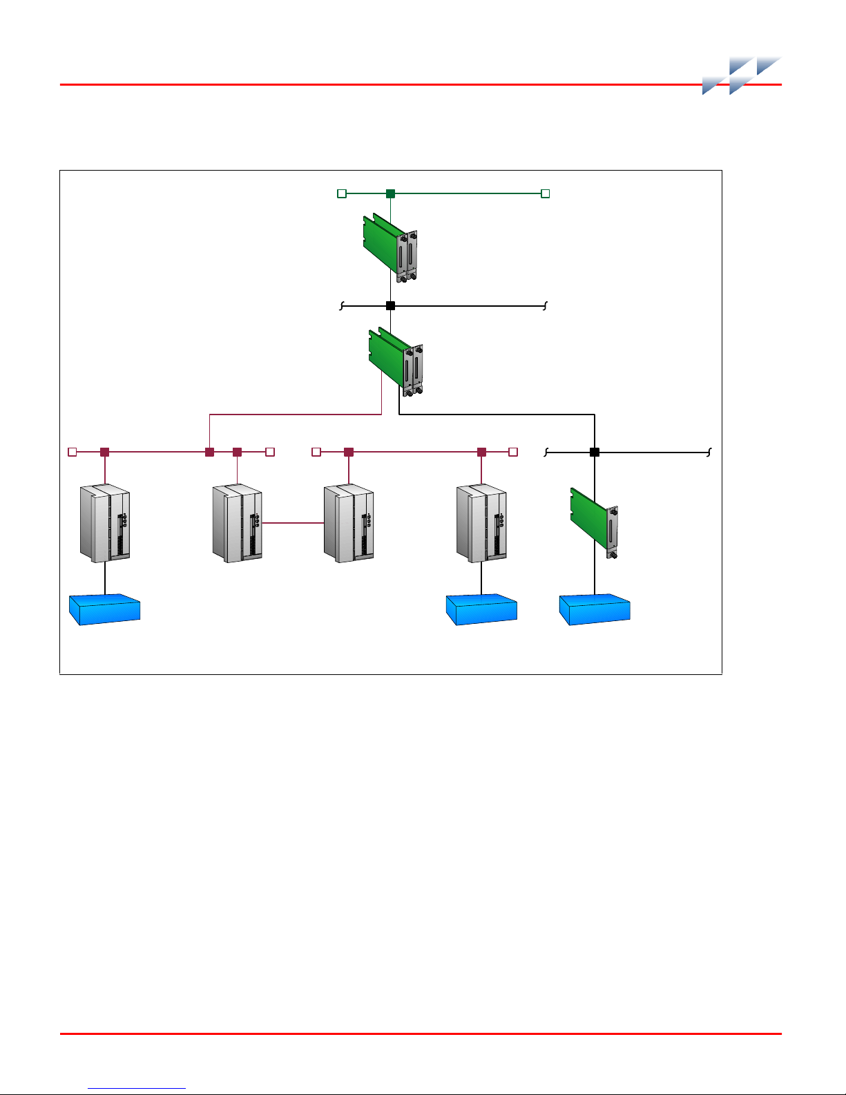
tions communication at a 40-kbaud rate. Figure 1-1 shows the
Harmony bridge controller architecture.
CNET
HARMONY RACK
COMMUNICATION
MODULES
CONTROLWAY
HARMO NY
BRIDGE
CONTROLLER
HNET
HARMONY
I/O BLOCKS
REPEATER
MOUNTING
UN IT (R M U )
HNET
RMU
Figure 1-1. Harmony Bridge Controller Architecture
Intended User
Personnel installing, operating or maintaining the BRC module
should read this instruction before performing any installation, operation, or maintenance procedures. Installation
requires an engineer or technician with experience handling
electronic circuitry. Formal training in Symphony system configuration (especially function codes) is helpful when configuring the BRC module.
HNET
HARMONY
I/O BLOCKS
REMOTE LOCATION
I/O EXPAN DER BUS
HARMONY RACK
I/O M O D U L E S
PROCESS I/OPROCESS I/O PROCESS I/O
T0246 7A
1 - 2 WBPEEUI230017B1
Page 14

Hardware Description
The Harmony bridge controller consists of a circuit board and
a faceplate.
Faceplate
The BRC faceplate measures 35.56-millimeters wide by
177.80-millimeters high (1.4-inches wide by 7.0-inches high).
Two latching screws, one at the top, the other at the bottom,
lock the module assembly in a module mounting unit (MMU). A
transparent window on the faceplate enables viewing the 16
CPU LEDs and the status LED. These LEDs display operating
information. A small hole directly below the window provides
access to the combination stop/reset pushbutton. Besides
locking the module in place, the faceplate also protects the circuit components and promotes proper air flow within the
enclosure.
Hardware Description
Circuit Board
The circuit board features state-of-the-art surface mount technology. On the board are nonvolatile random access memory
(NVRAM), static random access memory (SRAM), flash memory
(ROM), a microprocessor running at 32 megahertz, direct
memory access (DMA) circuits, ABB Process Automation custom bus circuits, and various support circuitry. The board
attaches to the faceplate with two screws. The module assembly occupies one slot in a module mounting unit.
A processor bus adapter board is required for connection to the
Harmony I/O subsystem via Hnet. It also connects to a termination unit for two auxiliary serial I/O ports and IISAC01 stations. Redundant BRC modules and Hnet buses connect
through redundant PBA boards.
Hardware Application
Because of the superior performance of the BRC module, applications that formerly required an external mainframe or minicomputer can now be handled in the Harmony control unit.
The large memory space and on-board communication ports of
the BRC module enable it to meet the sophisticated control
WBPEEUI230017B1 1 - 3
Page 15

Features
Features
application requirements of supervisory control, optimization
routines, performance assessment, and process modeling.
The Harmony bridge controller retains all of the features of the
INFI 90 OPEN multifunction processor modules. Additional
features of the Harmony bridge controller include:
• Simultaneous Hnet bus and I/O expander bus communi-
cation supports both Harmony I/O blocks and Harmony
rack I/O modules.
• Redundant Hnet bus.
• Online Hnet communication bus diagnostics and fault
isolation.
• Automatic downloading of Harmony I/O block
configurations.
• NVRAM battery power monitoring.
• Status output alarm monitoring.
• Two megabytes of on-board SRAM memory.
• Compatible with existing INFI 90 OPEN systems.
Instruction Content
This instruction consists of the following sections:
Introduction
Description and
Operation
Installation
Operating Procedures
Provides an overview of the module, a description of the hardware, a glossary of unique terms, and a table of physical, electrical and environmental specifications.
Uses block diagrams to explain the function of the key circuits.
Explains the handling, inspection, hardware configuration,
and installation aspects of the module.
Discusses the front panel indicators and controls, and everyday operation.
Troubleshooting
1 - 4 WBPEEUI230017B1
Features detailed flowcharts and tables that enable quick diagnosis of error conditions and provides corrective actions.
Page 16

How to Use this Instruction
Maintenance
Repair and
Replacement
Replacement and Spare
Parts
Appendices
Covers scheduled module maintenance.
Describes how to repair and replace the module.
Provides a list of part numbers and nomenclatures.
Provide quick reference information for NTMP01 hardware
configuration and step-by-step instructions for performing
online configuration.
How to Use this Instruction
Read this instruction in sequence. To get the best use out of
this instruction, read it from cover to cover, then go back to
specific sections as required. ABB strongly advises against
putting the module into operation until the installation section
has been read and performed.
1. Read and perform all steps in the installation section.
2. Thoroughly read the operating procedures section before
applying power to the module.
3. Refer to the troubleshooting section if a problem occurs.
This section will help to diagnose and correct a problem.
4. Go to the repair and replacement section for replacement
part numbers and nomenclatures, and for instructions on how
to replace the module.
Glossary of Terms and Abbreviations
Table 1-1 contains those terms and abbreviations that are
unique to ABB or have a definition that is different from standard industry usage.
Table 1-1. Glossary of Terms and Abbreviations
Term Definition
Controlway High speed, redundant, peer-to-peer communication link. Used to transfer infor-
mation between intelligent modules within a Harmony control unit.
Hnet Communications path between Harmony controller and I/O blocks.
Executive block Fixed function block that determines overall module operating characteristics.
WBPEEUI230017B1 1 - 5
Page 17

Reference Documents
Table 1-1. Glossary of Terms and Abbreviations
Term Definition
Function block The occurrence of a function code at a block address of a module.
Function code An algorithm which manipulates specific functions. These functions are linked
together to form the control strategy.
I/O block Generic name for a processor based Harmony input/output device: AIN-120,
AOT-150, CIO-100, DIO-400, etc.; comprised of an I/O module and a base.
I/O module Houses the I/O block circuitry; part of I/O block.
I/O expander
bus
MFT Machine fault timer. Reset by the processor during normal operation. If not reset
MMU Module mounting unit. A card cage that provides electrical and communication
PBA Processor bus adapter.
Termination unit Provides input/output connection between plant equipment and the Harmony
Parallel communication bus between the Harmony rack controller and Harmony
rack I/O modules.
regularly, the MFT times out and the module stops.
support for Harmony rack modules.
rack modules.
(continue d)
Reference Documents
Table 1-2 contains a list of documents referenced in this
instruction that provide information on BRC firmware and
related hardware.
Table 1-2. Reference Documents
Number Title
WBPEEUI200502?? Module Mounting Unit (IEMMU11, IEMMU12,
WBPEEUI210504?? Function Code Application Manual, Symphony
WBPEEUI230022?? Analog Control Station (IISAC01)
WBPEEUI240751?? Harmony Input/Output System
WBPEEUI240762?? IMDSO14 Digital Output Module
WBPEEUI260039?? NTMP01 Multifunction Processor Termination Unit
WBPEEUI270002?? Primary Interface, Composer
WBPEEUI270003?? Automation Architect, Composer
IEMMU21, IEMMU22)
1 - 6 WBPEEUI230017B1
Page 18

Related Nomenclatures
Table 1-3 lists nomenclatures related to the BRC module.
Table 1-3. Related Nomenclatures
Nomenclature Description
Related Nomenclatures
IEMMU11, IEMMU12,
IEMMU21, IEMMU22
IISAC01 Analog control station
NTMP01 Field termination panel
Module mounting unit
Specifications
Table 1-4 lists the specifications for the BRC module, process
bus adapter board and BRC redundancy kit.
Table 1-4. Specifications
Property Characteristic/Value
Microprocessor 32-bit processor running at 32 MHz
Memory All memory has 32-bit data path
SRAM NVRAM
Total Available Total Available
2 Mb 1.57 Mb 512 kb 441 kb 1 Mb
Power requirements 5 VDC at 2 A; 10 W typical (BRC)
Flash ROM
Tot al
Station support 128 40-kbaud serial stations (IISAC01) or eight 5-kbaud serial stations
Redundant controller
communication link
Programmability Function codes, C, Basic, Batch, Ladder, user-defined functions
Dimensions
BRC
PBA
Weight
BRC
PBA
WBPEEUI230017B1 1 - 7
5 VDC at 100 mA; 0.5 W typical (PBA)
4 MHz per byte per second (normal operation)
35.56 mm wide, 177.80 mm high, 298.45 mm long
(1.40 in. wide, 7.00 in.high, 11.75 in. long)
31.60 mm wide, 166.12 mm high, 102.62 mm long
(1.24 in. wide, 6.54 in. high, 4.04 in. long)
0.70 kg (24.69 oz)
0.30 kg (10.6 oz)
Page 19

Specifications
Table 1-4. Specifications (continued)
Property Characteristic/Value
Communication ports 2 RS-232-C or 1 RS-232-C and 1 RS-485,
1 SAC channel (128 SACs maximum
Ambient temperature 0° to 70°C (32° to 158°F)
Relative humidity 0% to 95% relative humidity up to 55°C (131°F) noncondensing
0% to 45% relative humidity at 70°C (158°F) noncondensing
Atmospheric pressure Sea level to 3 km (1.86 mi)
Certification CSA certified for use as process control equipment in ordinary
(nonhazardous) locations.
CE mark compliant for EMC directive and LV directive.
SPECIFICATIONS SUBJECT TO CHANGE WITHOUT NOTICE.
)
1 - 8 WBPEEUI230017B1
Page 20

Description and Operation
Introduction
This section explains the functionality of the Harmony bridge
controller (BRC) using block diagrams and text. Block diagrams divide the operation of the Harmony bridge controller.
Operation
The BRC module incorporates the power of a second generation 32-bit microprocessor operating at 32 megahertz. This is
coupled with 32-bit wide memory design with an optimized
interface. The microprocessor supplies superior performance
capable of supplanting the need for external mainframes or
minicomputers.
Control input/output is available from I/O blocks using Hnet
or from Harmony rack I/O modules using the I/O expander
bus. The data within the BRC module may be exported to the
Cnet communication network and to existing INFI-NET
Plant Loop communication systems.
Section 2
®
and
In some processes, the effects of a control failure in the system
can create dangerous situations or cause economic loss. To
reduce the possibility of these problems occurring, redundant
modules provide fail-safe control. Redundant BRC modules
link directly to each other via the processor bus adapter (PBA)
board or the BRC redundancy kit to keep the database in the
backup module current. Each module uses a redundant high
speed communication channel to accomplish this function. If
the primary module fails, the backup module is waiting in
standby mode and immediately takes over. The backup module
has the same control strategy loaded in its memory as the primary BRC module and is ready to assume control. When operating in Hnet communication mode, the redundant
communication channel insures that single point failures will
not prevent the backup module from being in a state of readiness to take over.
While the BRC module is controlling a process, it also executes
diagnostic routines. It is constantly checking the integrity of its
WBPEEUI230017B1 2 - 1
Page 21

Circuitry
hardware and firmware during normal operation. If the
diagnostic routines discover a module hardware or software
problem, it makes that information available to the operator.
The operator has access to this information through status
LEDs on the module faceplate and through reports received on
the human system interface (HSI) in module status bytes.
The BRC module uses a control I/O block (CIO) on Hnet to
support a station link that can handle up to 128 IISAC01
stations and is compatible with the Symphony system.
Two auxiliary RS-232-C ports and a serial station link are
available through a cable connection via the PBA board to an
NTMP01 Multifunction Processor Termination Unit. This station link can handle up to 64 IISAC01 stations at a 40-kilobaud rate or eight stations at a five-kilobaud rate. Various
handshake options are available via jumper configurations on
the termination unit.
Circuitry
Microprocessor
The BRC module has all the needed circuitry to operate as a
stand-alone controller. Direct memory access (DMA) operation
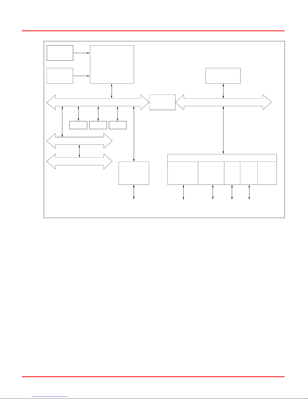
is supported for the station link. Figure 2-1 shows a block diagram of the BRC circuitry.
The microprocessor is responsible for module operation and
control. The BRC microprocessor is a 32-bit processor that
runs from a 32-megahertz clock. The microprocessor executes
synchronous access to long word memories and an asynchronous access to all byte ports. Since the microprocessor is
responsible for module operation, it communicates with all
blocks of the BRC circuitry. The microprocessor operating system instructions and the function code library reside in the
read only memory (flash ROM). The microprocessor carries out
all control responsibilities as it executes the control strategy
set up in its function block configuration.
The microprocessor constantly triggers the machine fault timer
(MFT) circuit. If the microprocessor or software fails, the MFT
circuit times out, issues a board wide reset, and the status
LED turns red. This condition is a fatal module error.
2 - 2 WBPEEUI230017B1
Page 22
CLOCK
MACHINE
FA U LT
TIME R
MICROPROCESSOR
LEDs,
SWITCHES,
DATA BUFFERS
Circuitry
32 -B IT D ATA PAT H
ROM NVRAM SRAM
16 -B IT D ATA PAT H
REDUNDANT HNET BUS
REDUNDANCY
Figure 2-1. Functional Block Diagram
Clock and Real-Time Clock
DUAL
LINK
STEERING
DATA
LOGIC
DMA /PERIPHERAL CONTROL I/O
CONTROLWAY/
MODULE BUS
8-BIT DATA PATH
I/O
EXPANDER
BUS
SAC/
DCS
TO
PROCESSOR
BUS ADAPTER
DUART RTC
T01272A
The clock section provides the clock signals to drive the microprocessor and associated peripheral devices. The clock/timer
section also includes a real-time clock (RTC).
Memory
The BRC memory is made up of one megabyte of flash ROM
memory, two megabytes of SRAM memory, and 512 kilobytes
of NVRAM memory.
The flash ROM memory holds the operating system instructions for the microprocessor. The SRAM memory provides temporary storage and a copy of the system configuration. The
NVRAM memory holds the system configuration (control strategy designed with function codes) and files for Batch, Basic, C,
WBPEEUI230017B1 2 - 3
Page 23

Circuitry
and UDF applications. NVRAM memory retains whatever information it has, even when it loses power.
Direct Memory Access
The DMA section enables the various communication links to
do direct data transfers to and from RAM memory without processor intervention. Communication links that support direct
memory access are the I/O expander bus, the dual redundancy link, the station serial link, and Controlway.
ABB-designed chips control DMA activity.
The DMA process greatly reduces the amount of work the
microprocessor needs to do when making data moves. This
greatly increases the speed of the BRC module by not
overloading the microprocessor with the work associated with
data moves. The microprocessor does not have to execute data
moves and is free to do other tasks.
Controlway
The Controlway is a high speed communication bus between
Harmony rack controllers. The BRC module uses this bus to
communicate with other control modules within a Harmony
control unit. It provides a one-megabaud, peer-to-peer communication link that can support up to 32 devices. The Controlway interface is provided by a custom integrated circuit
that links the BRC module to the Controlway. It has full DMA
capabilities (allowing for quicker operation), and two independent, redundant channels.
The redundant Controlway channels run through two paths on
the module mounting unit backplane circuit. The BRC module
transmits and receives data over both channels simultaneously. By receiving data through two channels, the BRC
module can check its integrity. In this way, the Controlway
minimizes the potential that a failure on a circuit board or
backplane will cause loss of module communication.
The Controlway interface also allows the BRC module to run
on module bus by operating in an 83.3-kilobaud mode (switch
selectable). The module bus operation option is provided to
support existing INFI 90 OPEN and Network 90
jumper allows the BRC module to be installed in systems using
early Network 90 modules that require -30 VDC. The jumper
®
systems. A
2 - 4 WBPEEUI230017B1
Page 24

Redundancy Link
Circuitry
disconnects -30 VDC from pin four of connector P2 on the BRC
module.
The redundancy link is a dual parallel link between a primary
and backup BRC module in redundant configurations. As the
primary module executes, the backup module waits in standby
mode and receives a copy of block outputs over this link. If for
any reason the primary module fails, the backup takes over
without any process interruption.
NOTE: Firmware revision levels must be the same in both primary and second-
ary BRC modules. If the firmware revision level is different and a failover
occurs, the redundant BRC module may operate erratically.
Two parallel channels of data and control signals connect by
way of a processor bus adapter board. Each BRC module in a
redundant configuration connect through PBA boards connected by redundant PBA cables. Both channels have parity
protection.
If no Hnet or termination unit communication is needed, the
primary and backup BRC modules connect by a BRC redundancy kit. The BRC redundancy kit contains two Harmony I/O
hood connection assemblies and a redundant PBA cable. The
connection assemblies replace the redundant PBA boards and
connect to each other through the redundant PBA cable.
Hnet Communication
An Hnet interface enables communication with Harmony I/O
blocks. All communication functions are handled by the Hnet
application-specific integrated circuit (ASIC). Hnet is a 16-bit
interface that operates via control registers in the I/O section
of BRC module memory and a one-megabyte memory space for
shared SRAM.
Hnet and I/O expander bus communication can be active
simultaneously if enabled, allowing the BRC module to utilize
both Harmony I/O blocks and Harmony rack I/O modules to
control a process. Function code 90 (S3) controls what combination of I/O interfaces are active. Three selections are
available: enable Hnet only, enable Hnet and I/O expander
bus, and enable I/O expander bus only.
WBPEEUI230017B1 2 - 5
Page 25

Circuitry
I/O Expander Bus
Physical connection is provided by a direct connection from the
BRC module P3 connector to the processor bus adapter board
P5 connector. The processor adapter board mounts on the rear
of a module mounting unit with the proper adapter brackets
installed. It uses cables to connect to the Harmony block
mounting columns. The PBA board provides Hnet physical
layer functions, termination, isolation relays, and BRC module
redundancy link.
The I/O expander bus interface is implemented using an
ABB-designed integrated circuit. The microprocessor can
select one of two modes of operation: DMA or auto mode. The
BRC software selects the mode of operation. Mode selection is
based on optimizing the number of bytes to be transferred. In
either mode of operation, the microprocessor does not need to
wait for each byte to transfer (as in previous controllers).
I/O Section
Serial Channels
The BRC module connects to the I/O expander bus through
the P2 connector on the module mounting unit backplane. It is
an eight-bit parallel bus that provides the communication path
for I/O data from Harmony rack I/O modules. The I/O
expander bus supports 64 low power I/O modules.
The I/O section interface allows the microprocessor to read the
switches that tell it how to operate and set the module address.
This section also contains latches whose outputs connect to
the status and error LEDs. This section monitors redundant
modules and outputs a signal to the LEDs of the primary module. Upon failover, this output de-energizes and the output of
the backup module energizes as it takes over. Additionally, the
I/O section monitors the stop/reset pushbutton. When the
pushbutton is pressed, the I/O section insures that the module completes any I/O functions before it stops the module.
Two independent serial channels (RS-485) are available on the
BRC module. Both serial channels are dedicated for language
support (C or Basic) or sequence of events recording. Clear to
send (CTS) and request to send (RTS) handshake signals are
supported. A DUART circuit on the processor bus adapter
2 - 6 WBPEEUI230017B1
Page 26

Circuitry
board supplies the serial channels with handshaking signals.
Clock signals for the baud rate generator are derived from an
on-board, 7.3728-megahertz oscillator.
The PBA board connects to an NTMP01 Multifunction Processor Termination Unit. Input/output signals enter or leave the
PBA board through a cable connection to the termination unit.
An NKTU01 or NKTU11 cable connects an NTMP01 termination unit. Standard D-type connectors are available on the termination unit.
To provide better noise immunity, both channels transmit and
receive differential serial signals based on the RS-485 standard. These signals are converted to normal RS-232-C voltage
levels by the termination unit. Each channel is capable of supporting standard RS-232-C baud rates up to 38.4 kilobaud.
The termination unit also provides optical isolation to eliminate the possibility of introducing ground loops into the system
from improper cable shield grounding. Channel A (the terminal
channel) can be selected to operate without the RS-485/
RS-232-C conversion allowing it to be used with differential
terminals or programmable logic controllers (PLC).
Station Link
Station communication originates from a DUART circuit on the
BRC module. This link controls the serial communication
between the BRC module and the control stations. It has two
modes of operation: Hnet transactions to a Harmony control I/
O block, or direct operation by the BRC module via a termination unit.
The Hnet-to-CIO block mode of operation allows stations to be
placed at greater distances from the BRC module because the
CIO block contains the physical interface to the station. The
BRC module is capable of communicating with a total of 128
IISAC01 stations attached to a total of 64 CIO-100/110 blocks.
NOTES: The system station maximum of 128 stations assumes that only Hnet-
to-CIO block communication mode is used.
The BRC module can also directly connect to local IISAC01 stations. Eight stations can be supported at the five-kilobaud rate
and up to 64 stations can be supported at the 40-kilobaud
rate. The BRC module makes this direct local connection
through the PBA board and appropriate termination hardware.
WBPEEUI230017B1 2 - 7
Page 27

Circuitry
Power
Support for bypass stations requires a Harmony control I/O
module (IMCIS12, IMQRS12) configured on the I/O expander
bus.
Power requirements are 5 VDC for logic power and for line drivers/receivers. The Hnet interface derives all other power
requirements from the 5 VDC logic power. Power for the module is supplied via the module mounting unit connection to the
BRC module P1 connector. The PBA board receives 5 VDC logic
power via its connection to the BRC module. The PBA board
uses this power for Hnet termination, and to power the isolation relays.
2 - 8 WBPEEUI230017B1
Page 28

Installation
Introduction
Section 3
This section explains how to set up and install the Harmony
bridge controller (BRC). Read, understand, and complete the
steps in the order they appear before operating the BRC
module.
The Harmony bridge controller requires a P-H-BRC-PBA1000
Processor Bus Adapter (PBA) board to support Hnet communication and BRC module redundancy. If no Hnet communication and termination unit is needed, a BRC redundancy kit
may be used to support redundancy instead of the PBA boards.
This section includes instructions for PBA board, BRC redundancy kit, and related cable installations.
NOTE: This module uses connections to the module mounting unit backplane
that served other functions in earlier Network 90 systems. To avoid potential
module damage, evaluate your system for compatibility prior to module instal-
lation. Earlier Network 90 systems applied -30 VDC to pins three and four of
the module connector P1. This voltage is not required for Symphony and
INFI 90 OPEN modules. In Symphony and INFI 90 OPEN systems, pin four is
used for the Controlway bus.
If the system contains modules that require -30 VDC, set jumper J3 to the
30 VDC position (jumper pins one and two). Doing so allows the installation of
the BRC module in a module mounting unit that uses -30 VDC and limits com-
munication to module bus. Refer to Table 3-6 for more information about setting
jumper J3.
WBPEEUI230017B1 3 - 1
Page 29

Special Handling
Special Handling
Observe these steps when handling electronic circuitry:
1. Use Static Shielding Bag.
shielding bag until you are ready to install them in the system.
Save the bag for future use.
2. Ground Bag Before Opening.
ing an assembly with semiconductors, touch it to the equipment housing or a ground to equalize charges.
3. Avoid Touching Circuitry.
avoid touching the circuitry.
NOTE: Always use ABB's field static kit (part number 1948385?1 - consisting
of two wrist straps, ground cord assembly, alligator clip and static dissipative
work surface) when working with the modules. The kit grounds a technician
and the static dissipative work surface to the same ground point to prevent
damage to the modules by electrostatic discharge.
Use Static Shielding Bag. Keep the modules in the static
Use Static Shielding Bag. Use Static Shielding Bag.
Ground Bag Before Opening. Before opening a bag contain-
Ground Bag Before Opening.Ground Bag Before Opening.
Avoid Touching Circuitry. Handle assemblies by the edges;
Avoid Touching Circuitry.Avoid Touching Circuitry.
4. Avoid Partial Connection of Semiconductors.
Avoid Partial Connection of Semiconductors. Verify that all
Avoid Partial Connection of Semiconductors. Avoid Partial Connection of Semiconductors.
devices connected to the modules are properly grounded before
using them.
5. Ground Test
Ground Test Equipment.
Ground TestGround Test
6. Use an Antistatic Field Service Vacuum.
Use an Antistatic Field Service Vacuum. Remove dust from
Use an Antistatic Field Service Vacuum.Use an Antistatic Field Service Vacuum.
the module if necessary.
7. Use a Grounded Wrist Strap.
Use a Grounded Wrist Strap. Connect the wrist strap to the
Use a Grounded Wrist Strap. Use a Grounded Wrist Strap.
appropriate grounding plug on the power entry panel. The
grounding plug must be effectively connected to the earth
grounding electrode system through the AC safety ground.
8. Do Not Use Lead Pencils to Set Dipswitches.
Do Not Use Lead Pencils to Set Dipswitches. To avoid con-
Do Not Use Lead Pencils to Set Dipswitches. Do Not Use Lead Pencils to Set Dipswitches.
tamination of dipswitch contacts that can result in unnecessary circuit board malfunction, do not use a lead pencil to set a
dipswitch.
Unpacking and Inspection
Equipment.
Equipment.Equipment.
1. Examine the hardware immediately to verify that it has not
been damaged in transit.
2. Notify the nearest ABB sales office of any damage.
3 - 2 WBPEEUI230017B1
Page 30
3. File a claim for any damage with the transportation company that handled the shipment.
4. Use the original packing material and container to store the
hardware.
5. Store the hardware in an environment of good air quality,
free from temperature and moisture extremes.
Dipswitches and Jumpers
This section explains how to configure and install the BRC
module. After installing the module, a function block
configuration must be created to define the functions the module will perform.
The BRC module has four configurable dipswitches, and four
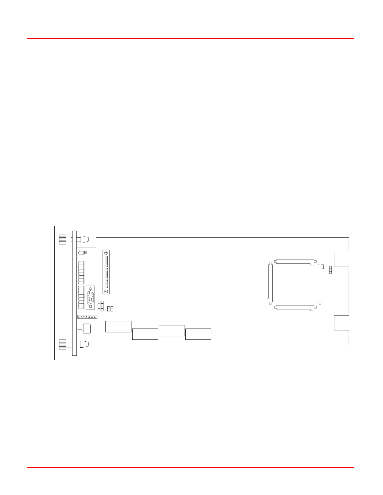
jumpers. Each dipswitch has eight poles. Figure 3-1 shows the
location of the dipswitches and jumpers on the circuit board.
Dipswitches and Jumpers
CR21
P5
15
J4
26
37
48
P4
J2
J1
P6
SW1
SW5
1 2 3 4 5 6 7 8
1 2 3 4 5 6 7 8
Figure 3-1. BRC Module Layout
Dipswitch SW5 sets the module address, bus speed, and operation mode (normal/diagnostic). Dipswitch SW2 sets module
options, enables special operations, and enables diagnostic
operations. Dipswitch SW4 sets module mounting unit and
memory options. Dipswitch SW3 is not used.
SW2
SW 3
1 2 3 4 5 6 7 8
SW4
1 2 3 4 5 6 7 8
P1
P10
J3
P11 P9
P3
P8
P2
T01274B
WBPEEUI230017B1 3 - 3
Page 31

Dipswitches and Jumpers
Jumpers J1, J2, J3, and J4 define module functions and operation. Jumper J1 enables or disables the machine fault timer
(MFT). Jumper J2 sets the diagnostic RS-232-C port for operation as data communication equipment (DCE) or data terminal
equipment (DTE). Jumper J3 disengages -30 VDC from the
module when installing it in a module mounting unit that supplies -30 VDC to other modules. Jumper J4 is reserved for use
by ABB engineering.
Dipswitch poles marked not used must be set to the default
settings listed in the appropriate table. The BRC module may
not operate properly if these dipswitches are improperly set.
Since factory settings do not reflect default settings, it is
imperative that all dipswitch settings be checked before putting the module into operation.
Dipswitch SW5 - Module Address
Dipswitch SW5 sets the module address, enables module diagnostics, and sets the bus mode. The BRC module can have an
address from zero through 31. Table 3-1 explains the functions
set by dipswitch poles one through three. Dipswitch poles four
through eight set the module address. Table 3-2 shows examples of how to set the address. Record the module address setting in the user setting portion of the table.
NOTES:
1. SW5 provides a module bus option to support existing INFI 90 OPEN and
early Network 90 systems. All modules within a process control unit must be
set to communicate on the same type of communication bus, either Controlway
or module bus.
2. Module addresses of redundant BRC modules must be identical.
Table 3-1. Dipswitch SW5 Settings (Operation)
Pole Setting Function
1 0 Normal run
1 Enable diagnostics using dipswitch SW2
2 0 Not used - do not change setting
Setting
User
3 - 4 WBPEEUI230017B1
Page 32

Table 3-1. Dipswitch SW5 Settings (Operation) (continued)
Dipswitches and Jumpers
Pole Setting Function
1
3
NOTE: 0 = closed or on, 1 = open or off.
1. The module bus setting is for support of existing INFI 90 OPEN and Network 90 systems.
0 Controlway (1 Mbaud)
1 Module bus (83.3 kbaud) or -30 VDC
operation
Dipswitch SW2 - Normal Operating Options
Dipswitch SW2 sets module options that are available when
the BRC module is in normal operation. Refer to Table 3-3 for
option setting information. The options listed in this table
Table 3-2. Dipswitch SW5 Settings (Address)
Dipswitch Pole
Address
Example
4
(16)5(8)
(Binary Value)
6
(4)
7
(2)
User
Setting
8
(1)
7 00111
15 01111
User s ettin g
NOTE: 0 = closed or on, 1 = open or off.
apply to normal operation. Normal operation options are
enabled when dipswitch SW2 pole one is set to closed (on). If
dipswitch SW2 pole one is set to open (off), special operations
are enabled. Refer to Dipswitch SW2 - Special Operations
for a description.
NOTE: Poles one through seven must have the same setting for both modules
when using redundant BRC modules.
Dipswitch SW2 - Special Operations
The special operations feature provides a means to configure
the BRC module to perform a one-time special operation rather
than entering its normal mode of operation. Setting dipswitch
SW2 pole one to open (off) enables the special operation mode.
WBPEEUI230017B1 3 - 5
Page 33

Dipswitches and Jumpers
Table 3-3. Dipswitch SW2 Settings (Operating Options)
Pole Setting Function
1 0 Disable special operations.
1 Enable special operations. Refer to Dipswitch SW2 - Special Opera-
tions.
2 0 Disable online configuration.
1 Enable online configuration.
3 0 Perform NVRAM checksum routine.
1 Inhibit NVRAM checksum routine.
4 0 Perform flash ROM checksum routine and file system check.
1 Inhibit flash ROM checksum routine and file system check.
5 0 Enable file system check.
1 Disable file system check.
6 0 Normal operation.
1 Compact configuration. The compact configuration function moves
configured function blocks to the top of the NVRAM while moving free
space to the bottom. To enable this function, open the pole and insert
the module into the module mounting unit. After a short time (directly
proportional to the configuration size), the module will return to the
mode it was in prior to being reset for the compact operation.
1
User
Setting
2
7 0 Normal operation.
1 Initialize. This operation destroys (erases) the module function block
configuration. Initialize NVRAM (erase configuration). Leave pole
open; insert module into module mounting unit. When group A LEDs
1, 2 and 4 are on, remove the module, put the pole in the closed position, and insert the module. The module is now ready to be configured. Use special operation two to initialize all NVRAM.
NOTE: This pole must remain closed for normal operation.
8 0 Primary BRC module.
1 Redundant BRC module.
NOTES: 0 = closed or on, 1 = open or off.
1. This setting is used by development personnel and should never be used for normal operation. The checksum provides additional module integrity and should be used whenever the module is controlling a process.
2. Leaving this option enabled causes the configuration to be compacted every time the module is reset, thereby increasing the
startup time. This increase becomes more substantial as the size of the configuration increases. Therefore, do not leave this
option enabled longer than necessary. Disabling this option stops any further compacting operations. It does not uncompact any
previously compacted configuration.
3. When redundancy is used, poles one through seven on the redundant BRC module are set the same as the primary BRC
module. Pole eight is set to closed (on) for the primary module and to open (off) for the secondary module.
3
3 - 6 WBPEEUI230017B1
Page 34

Poles two through eight select the special operation. The following steps explain how to set the BRC module for special
operations and reset it for normal operation. Table 3-4 shows
the dipswitch settings and explains each special operation.
To use special operations:
1. Set dipswitch SW2 pole one to open (off).
2. Set poles two through eight per Table 3-4. Begin with special operation two.
Table 3-4. Dipswitch SW2 Settings (Special Operations)
Dipswitches and Jumpers
Special
Operation
0 10000000 Force the BRC module into configure mode.
1
2
4 10000100 Cnet or INFI
5 10000101 Permit segment modification (allows change to segment scheme
Dipswitch Pole
Description
12345678
10000010 Initialize and format all NVRAM configuration space for Plant Loop
protocol.
-NET protocol enable. This allows the BRC module to
use the Cnet or INFI-NET capabilities.
configured with function code 82, specification S1).
6 10000110 Enable time-stamping. This operation instructs the BRC module to
generate time information with point data. It is applicable only to
Cnet or INFI-NET systems.
9 10001001 Enable simulation mode.
NOTE: 0 = closed or on, 1 = open or off.
1. Special operation two is for support of existing INFI 90 OPEN and Network 90 systems.
3. Insert the BRC module in its slot in the module mounting
unit (refer to Module Installation).
4. When the special operation is complete, the status LED
turns red and LEDs one through six illuminate.
5. Remove the BRC module.
6. Repeat Steps 2 through 8 for any other special operation
desired.
WBPEEUI230017B1 3 - 7
NOTE: Do special operation two as the first step of the module installation. If
installing the BRC module in a Cnet or INFI-NET environment, do special oper-
ation four next. For time-stamping, do special operation six next. To reverse
Cnet or INFI-NET protocol or time-stamping, do operation two again.
Page 35

Dipswitches and Jumpers
7. When all special operations are complete, reset pole one on
dipswitch SW2 to the closed (on) position.
8. Poles two through eight (module options) should be set for
the desired BRC operation per Table 3-4.
9. Insert the BRC module in its slot. It will begin normal
operation.
Dipswitch SW3 - Module Options
Dipswitch SW3 is not used. All poles should be set to closed
(on).
Dipswitch SW4 - Module Options
Dipswitch SW4 sets additional module options. This dipswitch
should be set to the user settings shown in Table 3-5.
Jumpers
Table 3-5. Dipswitch SW4 Settings (Module Options)
Pole Setting Function User Setting
1 - 4 — Not used 1
5 0 Disable SRAM multiple transfer 1
1 Enable SRAM multiple transfer
6 — Not used 0
7 0 Disable data cache 1
1 Enable data cache
8 0 Disable instruction cache 1
1 Enable instruction cache
NOTE: 0 = closed or on, 1 = open or off.
There are four jumpers (J1 through J4) on the BRC board.
These jumpers are for special hardware applications. They
define the RS-232-C diagnostic terminal as data terminal
equipment (DTE) or data communication equipment (DCE),
enable the machine fault timer and enable the module to oper-
3 - 8 WBPEEUI230017B1
Page 36

ate in a module mounting unit that uses -30 VDC. Refer to
Table 3-6 for an explanation of the functions set by jumpers.
NOTE: Jumper J1 is for ABB development personnel usage only. It is used to
disable the machine fault timer circuit. If this function is disabled (jumper pins
connected) and a problem develops in the BRC module, the module will not
halt, which may result in configuration corruption and unpredictable module
outputs.
Table 3-6. Jumpers Settings (J1 through J4)
Module Mounting Unit Preparation
Jumper Setting Function
J1 Open Not used. Must remain open for normal operation.
1
J2 Vertical
Horizontal Sets the RS-232-C diagnostic port to operate as DTE.
J3 30V Disconnects Controlway for operation in module mounting units that
MODB Allows operation in module mounting units that have Controlway
J4 Open Not used. Must remain open for normal operation.
NOTE:
1. Used by ABB service personnel. The J2 setting does not affect the module during normal operation.
Sets the RS-232-C diagnostic port to operate as DCE.
have -30 VDC (early Network 90).
communication. This setting must be used if dipswitch SW5 selects
Controlway.
Module Mounting Unit Preparation
Preparing the module mounting unit (MMU) consists of identifying the mounting slot, installing the required dipshunts, verifying the Controlway cable is installed, installing the processor
bus adaptor (PBA) board, PBA board cables, and Hnet
terminator.
User
Setting
Module Slot Assignments
Module placement within the module mounting unit is important. The BRC module requires a processor bus adaptor board
to use Hnet and BRC redundancy, or a BRC redundancy kit
when no Hnet and termination unit connection is needed. The
BRC module connects to the PBA board or the BRC redundancy kit at the rear of the module mounting unit. Redundant
BRC modules require mounting in adjacent MMU slots.
WBPEEUI230017B1 3 - 9
Page 37

Module Mounting Unit Preparation
Dipshunts
Disconnect power before installing dipshunts on the module
WARNING
mounting unit backplane. Failure to do so will result in contact
with cabinet areas that could cause severe or fatal shock.
No dipshunts are required if only Hnet is being used. If Hnet
and the I/O expander bus are being used or only the I/O
expander bus is being used, dipshunts are required to maintain bus continuity between all BRC modules associated with
one I/O expander bus segment. Check to see that dipshunts
are in place between all BRC module slots associated with one
I/O expander bus. One dipshunt goes between each module
slot to maintain bus continuity.
To check a particular BRC module configuration, read specification S3 of Extended Executive (function code 90). Specification S3 indicates if the BRC module is configured to operate in
Hnet mode only, Hnet and I/O expander bus mode, or I/O
expander bus mode only. Refer to the Function Code Applica-
tion Manual
tion Manual for details on function code 90.
tion Manualtion Manual
Function Code Applica-
Function Code Applica-Function Code Applica-
Controlway Cable
Install the Controlway cable in module mounting units as
follows:
1. Attach one end of the cable (twisted three-wire) to the bottom three tabs on the lower left of the module mounting unit
backplane (facing from behind). Refer to Figure 3-2.
2. Attach (in the same sequence) the other end of the cable to
the bottom three tabs on the lower left of the next module
mounting unit backplane.
NOTE: Because of high speed transaction constraints, a maximum of eight
related module mounting units (Controlways linked by cable) can be installed in
one enclosure. The number of interconnected module mounting units should
be kept to a minimum to avoid crosstalk and interference. Controlways cannot
be cable linked from enclosure to enclosure.
3 - 10 WBPEEUI230017B1
Page 38

Module Mounting Unit Preparation
T00063A
Figure 3-2. Controlway Cable Installation
PBA Board Installation
Hnet is the communication path between a BRC module and
Harmony I/O blocks. A PBA board is required to connect a
BRC module to Hnet, connect redundant Hnet to redundant
BRC modules, and provide a connection point for the NTMP01
termination unit (TU). The termination unit provides a connection for the two auxiliary serial ports and a direct five-kilobaud
or 40-kilobaud station link.
Mounting Bracket
A processor bus adapter mounting bracket is required to
install the PBA board. The processor bus adapter mounting
bracket consists of two mounting brackets and ten 5-40 ×
½-inch long, self threading screws, ten spacers, and ten flat
washers. Refer to the Module Mounting Unit (IEMMU11,
IEMMU12, IEMMU21, IEMMU22)
IEMMU12, IEMMU21, IEMMU22) instruction for more informa-
IEMMU12, IEMMU21, IEMMU22)IEMMU12, IEMMU21, IEMMU22)
tion on the module mounting unit.
Module Mounting Unit (IEMMU11,
Module Mounting Unit (IEMMU11, Module Mounting Unit (IEMMU11,
Disconnect power before installing the processor bus adapter
WARNING
WBPEEUI230017B1 3 - 11
mounting bracket on the module mounting unit backplane. Failure to do so will result in contact with cabinet areas that could
cause severe or fatal shock.
Page 39

Module Mounting Unit Preparation
To install the PBA mounting bracket:
1. Turn off power to the cabinet.
2. Install one PBA mounting bracket to the top of the module
mounting unit backplane assembly using five screws, flat
washers, and spacers. Refer to Figure 3-3.
3. Install the remaining mounting bracket to the bottom of the
backplane assembly using five screws, flat washers, and
spacers.
Cable and Terminator
There are two cable and terminator installation procedures
presented. The first procedure covers redundant installations
(two PBA boards), the second procedure covers nonredundant
(single PBA board) installations. Refer to Figure 3-4 for PBA
board cable connector assignments.
Redundant PBA Boards. To install the PBA board cables for a
redundant configuration (two PBA boards):
1. Install the redundant bridge controller link cable
(P-MK-HRM-PBA2000A) to both boards. Insert one of the keyed
connectors into the P4 connector on each PBA board.
2. Install the redundant processor bus adapter cable
(P-MK-HRM-PBA1?00?).
a. Position the end socket connector on the PBA assembly
bracket M3 studs. Install the two M3 nuts to maintain the
position of the connector.
b. Install a terminator (P-HA-MSC-TER10000) to the male
socket connector on the redundant bridge controller link
cable.
NOTE: The male socket connector is keyed, but the terminator is not. The ter-
minator can be installed in any direction.
c. Insert the next keyed connector on the cable into the P1
connector on the PBA board with the terminator mounted
to it.
d. Insert the next keyed connector on the cable into the P1
connector on the other PBA board.
3 - 12 WBPEEUI230017B1
Page 40

Module Mounting Unit Preparation
e. Attach the final cable connector to the I/O column after
the PBA boards have been mounted. Continue to Mounting
in this section to mount the redundant PBA boards.
NOTE: Termination unit cables for the direct station link can be installed at any
time after the PBA boards are installed. Refer to Appendix B for more
information.
Single PBA Board. For a single PBA board (nonredundant configu-
ration), install the redundant processor bus adapter cable
(P-MK-HRM-PBA1?00?):
1. Position the end socket connector on the PBA assembly
bracket M3 studs. Install the two M3 nuts to maintain the
position of the connector.
2. Install a terminator (P-HA-MSC-TER10000) to the male
socket connector on the redundant bridge controller link cable.
NOTE: The male socket connector is keyed, but the terminator is not. The ter-
minator can be installed in any direction.
Mounting
3. Insert the next keyed connector on the cable into the P1
connector on the PBA board.
4. The next keyed connector on the cable is used only for
redundant installations and has no purpose in single PBA
board installations. It can be left hanging.
5. Attach the final cable connector to the I/O column after the
PBA boards have been mounted. Continue to Mounting in this
section to mount the PBA board.
NOTE: The termination unit cable for the direct station link can be installed at
any time after the PBA board is installed. Refer to Appendix B for more
information.
There are two PBA board mounting procedures presented. The
first procedure covers redundant installations (two PBA
boards), the second procedure covers nonredundant (single
PBA board) installations. Figure 3-3 shows an example of how
the PBA board mounts to the PBA mounting bracket.
WBPEEUI230017B1 3 - 13
Page 41

Module Mounting Unit Preparation
5-40 x 0.50 IN.
SCREW S (10)
NOTE: MMU CARDCAGE
NOT SHOWN.
MMU
BACKPLANE
PBA MOUNTING BRACKET
(PART O F PBA MOUNTING KIT)
M3 x 8 mM
SCREWS (2)
ASSEMBLY
PBA
ASSEMBLY
HNET
TERMINATOR
PBA
PBA MOUNTING
BRACKET
BRC
MODULE
HNET
TERMINATOR
MM U BACKPLANE
ASSEMBLY
BRACKET
Figure 3-3. PBA Installation
3 - 14 WBPEEUI230017B1
BRC MODULEPBA MOUNTING
T01283A
Page 42

Module Mounting Unit Preparation
TO P3 OF
BRC-100
MODULE
TO REDUNDANT PBA
P4
TERMINATOR
(ON LAST PBA)
P-H-A-MSC-TER10000
P1
REDUNDANT BRIDGE
CONTROLLER LINK CABLE
PART NO. P-MK-HRM-PBA2000A
CONNECTION TO
TU CABLE FOR
P3P5
STATION LINK
REDUNDANT PROCESSOR BUS
ADAPTER CABLE
PART NO. P-MK-HRM-PBA1?00?
Figure 3-4. PBA Connector Identification
Redundant PBA Boards. To mount redundant PBA boards:
1. Locate and verify the adjacent MMU slots assigned to the
redundant BRC modules. Refer to Module Slot Assignments
in this section for more information.
2. For systems using both Hnet and I/O expander bus, or
only I/O expander bus, verify there is a dipshunt installed
between the adjacent MMU slots of each BRC module using a
particular I/O expander bus. Do not
dipshunts in systems using only Hnet. Refer to Dipshunts in
this section for information on how to verify a BRC module
communication bus configuration.
TO HARMONY
I/O COLU M N
REDUNDANT
PBA
Do not install any MMU
Do notDo not
T01284B
3. Insert each processor bus adapter assembly into position
in the module mounting unit.
WBPEEUI230017B1 3 - 15
Page 43

Module Mounting Unit Preparation
4. Align the two holes on each PBA mounting bracket with the
matching holes in the MMU backplane assembly mounting
bracket. Install two M3 × 8-mm long, Phillips pan head screws
and tighten to secure each PBA assembly to the PBA mounting
brackets on the MMU backplane assembly.
Single PBA Board. To mount a single PBA board:
1. Locate and verify the MMU slots assigned to the BRC modules. Refer to Module Slot Assignments in this section for
more information.
2. Insert the processor bus adapter assembly into position in
the module mounting unit.
3. Align the two holes on the PBA mounting bracket with the
matching holes in the MMU backplane assembly mounting
bracket. Install two M3 × 8-mm long, Phillips pan head screws
and tighten to secure the PBA assembly to the PBA mounting
brackets on the MMU backplane assembly.
BRC Redundancy Kit Installation
When no Hnet communication and no termination unit is
needed, the BRC redundancy kit (P-MK-HRM-BRC1000A) may
be used to provide a redundant connection between a primary
and backup BRC module.
To install the BRC redundancy kit:
1. Verify that the two BRC modules to be linked are mounted
adjacent to each other in the MMU, and are properly configured.
2. Insert one Harmony I/O hood connector to the P3 connector of each BRC module. Refer to Figure 3-5.
NOTE: The ends of the redundant PBA cable are keyed. When installing, make
sure that the slots between the hood connector and the redundant PBA cable
are properly aligned.
3. Link the two hood connectors using the redundant PBA
cable by firmly pressing the cable ends into the hood connector
sockets. When the cable ends are in place, the hood connector
brackets will snap into place. Refer to Figure 3-6.
3 - 16 WBPEEUI230017B1
Page 44

5-40 x 0.50 IN.
SCREWS (10)
REDUNDANT
PROCESSOR
BUS ADAPTER
CABLE
Module Mounting Unit Preparation
NOTE: MMU CARDCAGE
NOT SHOWN.
MMU
BACKPLANE
PBA MOUNTING BRACKET
(PART OF PBA MOUNTING KIT)
BRC
MODULE
MMU BACKPLANE
ASSEMBLY
HOOD
CONNECTOR
ASSEMBLY
Figure 3-5. BRC Redundancy Kit Installation
HOOD
CONNECTOR
ASSEM BLY
BRC MODULE
T04453A
WBPEEUI230017B1 3 - 17
Page 45

Module Installation
REDUNDANT PROCESSOR
BUS ADAPTER CABLE
Figure 3-6. Hood Connector Assembly Connector Identification
Module Installation
Never operate the BRC module with the machine fault timer circuit disabled (jumper pins connected). Unpredictable module
outputs and configuration corruption may result. The unpredictable module outputs may damage control equipment con-
CAUTION
nected to the BRC module.
P4TO REDUNDANT PBA
P5
TO P 3 O F
BRC-100
MODULE
T04454A
To avoid potential module damage, evaluate your system for
compatibility prior to module installation. This module uses
connections to the module mounting unit backplane that
served other functions in early Network 90 systems.
Pre-Installation Check
To determine if the module mounting unit uses -30 VDC:
1. Locate the -30 VDC faston. It is the second faston from the
top when viewing the module mounting unit from the rear.
2. Check for -30 VDC with respect to system common at
the -30 VDC faston.
3 - 18 WBPEEUI230017B1
Page 46

Installation
Module Installation
3. If -30 VDC is present, set jumper J3 and dipswitch SW5 to
the appropriate positions.
Before installing BRC modules:
1. Check all module dipswitch, and jumper settings (normal
and special operation).
2. Verify that the PBA board is attached to the proper slot on
the module mounting unit backplane.
3. Modules can be installed and removed under power. When
doing so, the status LED will turn red momentarily and then
turn green. If it does not, refer to Section 5 for troubleshooting
information.
To install the BRC module:
1. Slide the BRC module into its mounting slot while guiding
the top and bottom edges of the module along the top and bottom rails of its assigned slots in the module mounting unit.
2. Push on the faceplate until the rear edge of the module is
firmly seated in the P5 connector of PBA board.
NOTE: If installing the BRC module under power, verify the status LED
momentarily lights red and then remains green. If this does not occur, refer to
the troubleshooting section for corrective action.
3. Turn the two latching screws ½-turn to lock the module in
place. The module is locked into place when the open end of
the slot on each latching screw faces the center of the
faceplate.
WBPEEUI230017B1 3 - 19
Page 47

WBPEEUI230017B1
Page 48

Operating Procedures
Introduction
The first part of this section explains Harmony bridge controller (BRC) startup, LED indications, and stop/reset. The last
part explains the three modes of operation.
Startup
When power is applied to the BRC module, it does an internal
check, checks its configuration, and builds the necessary databases.
During startup of the primary BRC module, the front panel
LEDs will go through the following sequence:
1. All front panel LEDs will illuminate red.
Section 4
2. The status LED will change from red to green.
3. Group A LEDs one through six will go out.
4. Group B LEDs one through eight will go out.
During startup of the secondary BRC module, the front panel
LEDs will go through the following sequence:
1. All front panel LEDs will illuminate red.
2. The status LED will change from red to green.
3. All LEDs will go out.
4. Group A LED seven will illuminate red and then go out.
5. Group A LED eight will illuminate red.
If the appropriate LEDs do not illuminate, refer to Section 5 for
more details.
WBPEEUI230017B1 4 - 1
Page 49

Module LEDs
Module LEDs
There are 17 LEDs visible through the faceplate window. Eight
group A and eight group B LEDs relate to processor status,
and one is the module status LED (Fig. 4-1).
RED/GREEN
STATUS LED
STOP/RESET
SWITCH
GROUP A
LEDS
GROUP B
LEDS
BRC-100
1
2
3
4
A
5
6
7
8
1
2
3
4
B
5
6
7
8
T0 1273B
Figure 4-1. Front Panel
Front Panel LEDs
Group A LEDs display codes if a BRC module error occurs during normal operation. Additionally, in redundant configurations, they show which module is the primary and which is the
secondary. Group B LEDs display the pass and fail counts
when the module is in diagnostic mode. Group A LEDs seven
and eight are on if the module is primary; group A LED eight is
on if the module is secondary. If an error occurs, the status
4 - 2 WBPEEUI230017B1
Page 50

LED turns red and the group A LEDs light up to display the
error code (Table 5-1).
NOTE: Both groups of LEDs one through eight are on when the system is first
coming up. This is normal. It means that the BRC module is not yet online.
Red/Green Status LED
The status LED is a red/green LED. It shows BRC operating
condition. There are four possible states.
Off
No power to the BRC module, or the module is powered and
jumper J4 is installed. Jumper J4 must remain open for normal operation. The status LED momentarily goes off when the
microprocessor initializes on startup.
Stop/Reset Switch
Solid Green
Flashing Green
Solid Red
The BRC module is in execute mode.
The BRC module is in execute mode but there is an NVRAM
checksum error, or the module is in the configure or error
mode.
The BRC module diagnostics have detected a hardware failure,
configuration problem, etc., and stopped the module. Additionally, the group A LEDs will illuminate in a certain sequence to
display the error code.
Stop/Reset Switch
NOTES:
1. Do not remove an operational BRC module under power unless the
stop/reset switch has been depressed once and the module has halted (status
LED is red and group A LEDs one through six are on). This procedure must be
followed when removing a BRC module from a redundant configuration. An
operational module must halt operation before control passes to the secondary
module.
The stop/reset switch is a two-hit switch. It stops the BRC
module in an orderly manner, preventing glitches on the bus.
The switch is accessible through the opening on the faceplate
(Fig. 4-1). Since the opening is small, pressing the switch
requires a thin round object. Pressing the switch once stops
WBPEEUI230017B1 4 - 3
2. Firmware revision levels must be the same in both primary and secondary
BRC modules. If the firmware revision levels are different and a failover occurs,
the secondary BRC modules may operate erratically.
Page 51

Modes of Operation
operation. Always stop the BRC module before removing it
from the module mounting unit. Stopping the BRC module this
way causes it to:
• Save and lock the BRC module configuration.
• Complete any nonvolatile memory write operations in
progress.
• Deactivate all communication links.
• Transfer control from the primary BRC module to the sec-
ondary module in redundant configurations.
• Change the status LED color to red.
Once the BRC module is stopped, pressing the switch again
resets the module. Use the reset mode to:
• Reset the default values to the power-up values.
• Recover from a BRC module time-out or operator-initiated
stop.
NOTE: Pressing and holding the stop/reset switch provides no additional func-
tionality over pressing and releasing the switch. It will only stop the BRC mod-
ule. To stop the module, press and release the stop/reset switch. To reset the
module, press the stop/reset switch a second time. If the BRC module halts
due to an error (causing the status LED to turn red), a single push of the
stop/reset switch resets the module.
Modes of Operation
The BRC module has three operating modes: execute, configure, and error.
Execute
The execute mode is the normal mode of operation. In this
mode, the BRC module communicates with I/O blocks, rack
I/O modules, and other control modules. It executes control
configurations, reads inputs, and updates outputs. The BRC
module also processes exception reports, and configuration
and control messages.
4 - 4 WBPEEUI230017B1
Page 52

Modes of Operation
Configure
Error
Use the configure mode to enter control strategies. The BRC
module receives configuration commands over Controlway and
changes the data in the NVRAM memory.
NOTE: The process of configuring the BRC module requires information from
at least two documents. The Function Code Application Manual contains all
of the information needed to design a control strategy. The instruction for the
particular configuration tool being used (e.g., Composer) explains the steps
required to download control strategies into module memory.
The BRC module goes into error mode whenever the built-in
system diagnostics detect a hardware or configuration error. If
a hardware error is detected, the module halts and displays the
error code using group A LEDs one through eight. If an NVRAM
error is detected, the status LED flashes, but the module continues to operate. This is possible because a copy of the configuration is held in SRAM and executed from there. The next
time the module is reset it will not start up, but will fail with an
NVRAM error.
WBPEEUI230017B1 4 - 5
Page 53

WBPEEUI230017B1
Page 54

Troubleshooting
Introduction
This section contains Harmony bridge controller (BRC) troubleshooting information. Included is information on module
error codes, troubleshooting flowcharts, diagnostic routines,
and the module status summary.
Error codes provide specific module fault information and
appropriate corrective action. Troubleshooting flowcharts provide a quick look at hardware associated problems that may
occur during module installation and startup. Diagnostic tests
help determine if there is a problem with module components
or circuitry. They are useful for testing the module when the
system is down or there is some other means of controlling the
process. For example, use the backup module (if redundant
modules are installed) to control the process while testing the
primary module. The module status summary is a 16-byte
module status record that provides summary flags for error
conditions, module type, and firmware revision level.
Section 5
Error Codes
BRC module error codes are listed in Table 5-1. The module
displays error codes on group A LEDs. Table 5-2 lists status
LED states and other conditions that are indicated by
LEDs.
Table 5-1. Error Codes
1
Code
01 00000001 NVRAM checksum error Initialize NVRAM. If error recurs call ABB
02 00000010 Analog input calibration Check I/O module error.
03 00000011 I/O module status bad Check module status and I/O modules.
05 00000101 Configuration error
LED
87654321
Condition Corrective Action
(undefined block)
field service.
Check module status undefined block
(modules referenced).
WBPEEUI230017B1 5 - 1
Page 55

Error Codes
Table 5-1. Error Codes
1
Code
06 00000110 Configuration error (data type
08 00001000 Trip block activated Check module status.
0A 00001010 Software programming error Internal error. If error recurs, call ABB field
0B 00001011 NVRAM initialized Confirm that NVRAM is initialized; no
0C 00001100 NVRAM opened for write Initialize NVRAM. If error recurs, call ABB
0D 00001101 Intermodule link error Check the cable connection between pri-
0E 00001110 Redundancy IDs the same Put position 8 of SW2 in the opposite posi-
0F 00001111 Primary failed, backup can-
87654321
LED
(continued)
Condition Corrective Action
mismatch)
not take over, configuration
not current
Check module status (data type) modules.
service.
action is required.
field service.
mary and secondary BRC modules at the
PBA board.
tion of the primary module SW2 position 8.
Check configuration. Correct any faulty
values. Execute the configuration.
10 00010000 Primary failed, backup can-
not take over, data not check
pointed
11 00010001 Error during write to
nonvolatile memory
12 00010010 Backup and primary module
addresses are different
13 00010011 ROM checksum error Contact ABB field service.
14 00010100 BRC set for
INFI-NET/Superloop but in a
Plant Loop environment
17 00010111 Duplicate Controlway
address detected
1D 00011101 Hnet failure Check Hnet cabling and connections to
20 00100000 C program format error Repeat configuration download.
21 00100001 File system error Check file directory, replace bad file.
Check configuration. Correct any faulty
values. Execute the configuration.
Set addresses the same.
Reformat BRC module
Set address to unique value in PCU.
PBA board, terminations, and Harmony
I/O blocks. Replace the BRC module if
Hnet cabling and connections check out.
.
5 - 2 WBPEEUI230017B1
Page 56

Error Codes
Table 5-1. Error Codes
1
Code
22 00100010 Invoke C error Check C program and invoke C blocks,
23 00100011 User write violation Check C program, correct and rerun.
24 00100100 C program stack overflow
25 00100101 Configureable Logic Interface
28 00101000 User defined function (UDF)
29 00101001 UDF function block cannot
2A 00101010 Not enough memory for UDF Revise configuration
2B 00101011 Missing UDF declaration Add function code 190 to configuration.
2C 00101100 Wrong UDF type Put correct UDF type in configuration.
87654321
LED
(continued)
Condition Corrective Action
Function Code incompatible
with firmware
block number reference
invalid
read program
correct and rerun.
Check firmware revision level. Verify that it
supports the revision the CLIF was compiled for.
Check configuration. Fix block configuration. Fix block reference.
Check configuration. Fix UDF block file.
.
2D 00101101 Missing UDF auxiliary Put function code 198 in block
configuration.
2E 00101110 UDF compiler and firmware
incompatible
2F 00101111 Basic program error Check Basic program, correct and rerun.
30 00110000 Primary active during failover
attempt
31 00110001 Memory or CPU fault Replace BRC module. If error recurs, call
32 00110010 Address or bus error Reset BRC module. If error recurs,
33 00110011 Illegal instruction
34 00110100 Internal error - trace/privi-
lege violation
35 00110101 Internal error -
spurious/unassigned exception
36 00110110 Internal error - divide by 0 or
check instruction
37 00110111 Internal error - undefined trap Restart BRC module. If error recurs,
Check firmware revision level. Verify that it
supports UDF.
Replace primary and/or backup to determine faulty module.
ABB field service.
replace BRC module.
Reset BRC module. If error recurs,
replace BRC module.
replace BRC module.
38 00111000 Board level hardware error Contact ABB field service.
WBPEEUI230017B1 5 - 3
Page 57

Error Codes
Table 5-1. Error Codes (continued)
1
Code
3F 00111111 Normal stop None.
40 01000000 Backup - cold takeover ready
80 10000000 Backup - hot takeover ready
C0 11000000 Primary - operating
2
XX
NOTES:
1. Code numbers are hexadecimal digits.
2. This symbol represents any LED combination not specifically addressed in this table.
LED
Condition Corrective Action
87654321
— Unknown Contact ABB field service.
Table 5-2. Status LED and Other Conditions
LED Condition Corrective Action
Status Off Check power.
Check module seating.
Check jumper J4. Remove if installed.
If power and seating are okay, remove the module
and replace with identically configured module.
Group A
6/7/8
Group A
7/8
Red Press reset button. If LED remains red, remove the
module and replace with identically configured module.
Green None - normal.
Off Check power.
Check module seating.
If power and seating are okay, remove the module
and replace with identically configured module.
Red None - indicates primary module is in simulation
mode.
Off Check power.
Check module seating.
If power and seating are okay, remove the module
and replace with identically configured module.
Red None - indicates primary module.
5 - 4 WBPEEUI230017B1
Page 58

Flowcharts
Flowcharts
Diagnostics
Table 5-2. Status LED and Other Conditions
LED Condition Corrective Action
Group A
8
The flowcharts in Figures 5-1 and 5-2 provide a quick look at
hardware related problems that may occur during module
installation and startup. Use the flowcharts to troubleshoot
problems that may have occurred because of improper hardware installation.
Off Check power.
Check module seating.
If power and seating are okay, remove the module
and replace with identically configured module.
Red None - indicates backup module in redundant
configuration.
(continued)
Overview
The BRC firmware contains diagnostic routines that can be
invoked during module power up. These routines verify the
proper operation of the module components and circuitry. Putting the BRC module in the diagnostic mode allows the module
to perform a variety of diagnostic tests but suspends normal
operation. Therefore, use it during installation to check module
integrity, when the system is down, or transfer system control
to a backup BRC module to check a currently operating module. Refer to Diagnostic Test Selection in this section for
information on how to use the diagnostic routines. Table 5-5
lists each test routine and gives a brief description.
Use the BRC dipswitches to select the required diagnostic routine. Diagnostic test results display on the BRC module front
panel LEDs. Both group and individual tests can be executed.
The typical procedure is to select a diagnostic routine to execute, set the module dipswitches accordingly, reset the module, and observe the results on the faceplate LEDs. If the halt
on error feature is disabled, the selected test runs repeatedly
until the module is reset and another test is selected. If halt on
WBPEEUI230017B1 5 - 5
Page 59

Diagnostics
START
NO
STATUS
LED OFF?
YES
POWER ON?
YES
BRC
MODULE SEATED
IN M M U ?
YES
REMOVE M ACHINE
FA U LT T IM E R
JUMPER FROM BRC
MODULE
CHECK +5 VDC
OUTPUTS ON
MMU BACKPLANE
+5 VDC
ON MM U
BACKPLANE?
YES
NO
NO
NO
TURN ON
POWER
SEAT BRC
MODULE IN MMU
BACKPLANE
TROUBLESHO OT
POWE R SYSTEM.
NO
REFER TO APPLICABLE
INSTRUCTIONS
STATUS LED
RED?
YES
ERROR CODE
DISPLAYED?
YES
PERFORM
CORRECTIVE
ACTION APPLICABLE
TO ERROR CODE
DISPLAYED
RESET
BRC MO DULE
STATUS
LED RED?
YES
NO
NO
NO
STATUS LED
ORANGE?
YES
REMOVE MACHINE
FAULT TIMER
JUMPER FROM
BRC MO DULE
NO
STATUS LED
GREEN?
YES
DONE
RE PLACE
BRC MO DULE
REPLACE
BRC MO DULE
T01270A
Figure 5-1. Troubleshooting Flowchart (Serial Port)
error feature is enabled, the test stops and the LEDs display
the failure.
An additional module is required for I/O expander bus communication tests. To test I/O expander bus communications:
1. Set the dipswitches on the IMDSO14 (DSO) module and the
BRC module to the settings in Table 5-3.
2. Insert the DSO module in the same module mounting unit
(MMU) as the BRC module.
5 - 6 WBPEEUI230017B1
Page 60

START
Diagnostics
RS-232-C
LINE ERRORS
ON BRC LEDs
(CO DE 15 )?
YES
F1
OPEN ON
TU?
YES YES
REPLAC E F1
WITH 1.0 A
250 V FUSE
NO
NO NO
CROSSOVERS CONNECT
JUMPER SETTINGS M ATCH
DONE
+24 VDC
CONNECTED TO
TU?
MEASURE
24 VDC AT
TU?
YES
RS-232-C
CABLE WITH NO
TU (P5 O R P6) TO
COMPUTER?
YES
HANDSHAKE
APPLICATION?
REFER TO NTMP01
INSTRUCTIONS TO
CONNECT POWER
NO
CHECK POWER
CABLING TO TU/TM.
CHECK POWER
NO
REPLACE CABLE WITH
CABLE HAVING STRAIGHT
PIN TO PIN CONNECTION
BETWEEN DB-25
CONNECTORS
NO
SYSTEM.
SET JUM PER S
FOR APPLICATION
YES
TU
CABLE INSTALLED
AND CONNECTED TO
BRC P3?
YES
RS-232-C
LINE ERRORS
ON BRC LEDs
(CO DE 15 )?
YES
CONTACT
ABB
TECHNICAL
SUPPORT
Figure 5-2. Troubleshooting Flowchart (Status LED)
NO
NO
INSTALL TU
CABLE
DONE
T01271C
WBPEEUI230017B1 5 - 7
Page 61

Diagnostics
Table 5-3. DSO and BRC Setup for I/O Expander Bus Test
Module Address Dipswitch
IMDSO14 S1 00001111
BRC-100 SW3 00001111
NOTE: 0 = closed or on, 1 = open or off.
3. There must be continuity between the DSO and BRC modules on the I/O expander bus (i.e., I/O expander bus dipshunts inserted with straps intact between the DSO and BRC
modules). The modules do not need to be in adjacent slots.
An additional NTMP01 termination unit (TU) is required for
redundancy link and SAC link tests.
Diagnostic Test Selection
Pole one of dipswitch SW5 must be set to the open (off) position
to put the module into the diagnostic mode. The remaining
poles on dipswitch SW5 are used to select the module address
and communication bus mode. They should remain in their
normal operating position. Use dipswitch SW2 to select diagnostic tests. Table 5-4 defines the function of each pole of
dipswitches SW2 and SW5.
Pole
12345678
Table 5-4. Diagnostic Dipswitch Settings
Dipswitch Pole Setting Function
SW5 1 1 Diagnostics mode. Test selected with
SW2.
2 0 Not used.
3 0 Controlway mode.
1 Module bus mode.
4 - 8 0 - 31
(dec)
SW2 1 0 Special operations disabled.
2 0 Not used.
3 - 8 0 - 2B
(hex)
NOTE: 0 = closed or on, 1 = open or off.
Module address. Refer to Table 3-1.
Test number (ID). Refer to Table 5-5.
5 - 8 WBPEEUI230017B1
Page 62

Diagnostics
On dipswitch SW2, poles three through eight select the diagnostic test. Pole eight is the least significant bit (binary weight
one); pole three is the most significant bit (binary weight 32).
Refer to Table 5-5 for test ID values. Pole one selects a special
operations feature. When enabled, the BRC module will halt
test execution whenever the selected test detects an error. The
number of the failing test is displayed on the group A LEDs
(Fig. 5-3). The group B LEDs display the pass/fail count. Refer
to Table 5-5 for a description of each diagnostic test.
Table 5-5. Diagnostic Tests
Test Name Test-ID Description
Switches and LEDs 00 Byte value of all dipswitches are exclusive ORed together. Results
are displayed on LEDs. Status LED is off for even or on for odd
total.
CPU 01 Verifies CPU instruction set is operational.
ROM 02 Calculates checksum of ROM and compares it to value stored in
ROM during programming.
RAM 03 Performs walking one test. Clears, verifies, sets and verifies all
RAM. Test includes byte, word and long word accesses.
NVRAM 04 Verifies read and write function of NVRAM.
Timer 05 Initializes DUART timer for 1-msec interrupts and then waits for it
to time-out.
Real-time clock 06 Verifies real-time clock is functioning.
I/O expander bus
stall
Controlway 08 Sends series of bytes to Controlway verifying timing and transfer
Dispatcher IRQ2 09 Issues software dispatcher request and waits for interrupt to occur.
DUART 0 0A Tests (in local loopback mode) both serial channels of DUART cir-
DUART 1 0B Tests (in local loopback mode) both serial channels of DUART cir-
Immediate INT 0C Sets and resets all interrupt levels verifying proper operation.
Hnet
(local loop back)
07 Sets a latch enabling a level seven interrupt to occur.
status.
cuitry that supports the RS-232-C/RS-485 serial ports.
cuitry that supports station link and debug port.
0D Test Hnet interface in local loop back mode. Checks Hnet ASIC
operation including both channel A and B, shared RAM, timers,
time-sync, registers, etc.
ID ROM 0E Reads CRC code from ID-ROM.
Unused 0F —
Group test 1 10 Executes tests 01 through 0F.
WBPEEUI230017B1 5 - 9
Page 63

Diagnostics
Table 5-5. Diagnostic Tests
Test Name Test-ID Description
I/O expander bus
1
test
Unused 12 —
SAC link
controller/station
Redundancy link primary/backup
Hnet 16/21 Tests Hnet communication between a BRC module acting as a
(continued)
11 BRC module performs status read and verifies the IMDSO14
(address 15) responds over I/O expander bus. IMDSO14 LEDs
count successful tests.
13/23 Test station link (IISAC01) communication between a BRC module
acting as a controller and another BRC module acting as a station.
Checks the ability to perform direct memory accessed data transfers across the RS-485 station link at 40-kilobaud rate. Requires
two BRC modules (redundant) and the appropriate PBA and
redundancy cabling. The master BRC module will provide pass/fail
indication; the station BRC module will display data received and
transmitted.
14/24 Tests communications between redundant BRC modules. Checks
the ability to perform direct memory accessed data transfers
across both redundancy link channels. Requires two BRC modules
(redundant) and the appropriate PBA and redundancy cabling or
BRC redundancy kit. Set one module to test 14 (primary); the other
to test 24 (backup). The primary BRC module will provide pass/fail
indication; the backup BRC module will display data received and
transmitted.
master and another BRC module acting as an I/O device. Checks
the ability to both transmit and receive Hnet messages. Requires
two BRC modules (redundant or nonredundant) and the appropriate PBA, Hnet cabling, and termination hardware. Set one BRC
module to test 16 (master); the other to test 21. Both BRC modules
provide pass/fail indication.
NOTE: A Harmony I/O block set at test 21 can also serve as the
I/O device. This is the recommended setup for testing Hnet.
Unused 15-1F —
Group test 2 20 Executes tests 01 through 1F.
SAC station and
redundancy link
backup
I/O expander bus
fault time halt
5 - 10 WBPEEUI230017B1
2
22 Displays running count of bytes received by backup BRC module
when primary BRC is executing test 20. Provides the common
functionality of both tests 23 and 24.
25 Arms the fault timer and allows the I/O expander bus clock to stall.
This checks the BRC module ability to disengage from the I/O
expander bus in the event it can no longer drive the expander bus
clock. This test passes if module halts with a 0x55 pattern displayed on the LEDs. Fails if module continues to operate with any
other pattern displayed on the LEDs.
Page 64

Table 5-5. Diagnostic Tests (continue d)
Test Name Test-ID Description
Diagnostics
NVRAM retention data storage
NVRAM retention data check
Unused 28 —
Stop pushbutton
Memory management unit
Station link 2B Tests the BRC module ability to communicate with a single
NOTES:
1. Requires the IMDSO14 module (Table 5-3).
2. Test is not continuous. The BRC module halts and displays a nonstandard pass/fail indication.
2
2
2
26 Stores a known data pattern in NVRAM for testing by the NVRAM
retention - data check test 27. Halts with LED pattern 0x55 if test
has completed writing data.
NOTE: Remove power from module prior to running the NVRAM
retention - data check test. If practical leave module unpowered for
one hour prior to running the data check test.
27 Verifies NVRAM holds data pattern stored in test 26. Provides nor-
mal pass/fail indication.
29 Verifies proper pushbutton operation. Passes if after pressing the
stop pushbutton once, LED display changes from 0x29 to 0x55
with the red/green LED red.
2A Verifies the ability of the memory management unit hardware to
detect legal and illegal accesses to the BRC module memory
address space. Passes if the module halts with the LED pattern
0x23 (user write violation halt code). Fails if the module continues
to operate or halts with any other LED pattern.
IISAC01 station set at a 40-kilobaud rate and station address
seven. Passes if the bar graphs of the station ramp up and no E01
error occurs.
LED Display
The front panel LEDs (Fig. 5-3) are used during diagnostic
mode operation to display test results.
On module reset, all front panel LEDs turn on. Next, the BRC
module reads the dipswitches, executes the selected test, and
displays the result on the group A and B LEDs. Group A LEDs
display the test number on LEDs one through six. If LED eight
is on, the test failed. The display is latched on for
viewing ease, then the LEDs blank out for about
and the test is repeated. Group B LEDs display a running tally
of successes and failures. LEDs one through four tally the
passes; LEDs five through eight tally the failures.
WBPEEUI230017B1 5 - 11
1
/4-second for
1
/8-second,
Page 65

Module Status Summary
GROUP A
LED s
LED 1
LED 2
LED 3
TEST NUMBER
LED 4
LED 5
LED 6
LED 7
LED 8
LED 1
LED 2
LED 3
GROUP B
LED s
Figure 5-3. LEDs - Pass/Fail
LED 4
LED 5
LED 6
LED 7
LED 8
NOT USED
TEST NUMBER
MO D E FA IL
LSB
PASS COUNT
MSB
LSB
FAILURE COUNT
MSB
T01419A
If a test fails with the special operations feature selected
(dipswitch SW2, pole one on), the status LED turns red. The
test number that failed is displayed on the group A LEDs.
For group tests (10, 20), each test is run in numerical order.
On a failure, group A LED eight flashes and LEDs one through
six display the test number that failed. When all tests in the
group are done, the error count is incremented and displayed
on the group B LEDs.
Module Status Summary
The BRC module has a 16-byte module status record that provides summary flags for error conditions, module type, and
firmware revision level. Table 5-6 shows the fields of the BRC
5 - 12 WBPEEUI230017B1
Page 66

Table 5-6. Status Report
Module Status Summary
status report. Table 5-7 lists the definition of each field within
the module status report. Refer to the appropriate human system interface (HSI) instruction for an explanation of how to
access the module status report.
Byte
76543210
1 ES Mode Type
2 FTX BAC RIO LIO CFG NVF NVI DSS
3 Error code
4 Error code descriptor (1)
5 Error code descriptor (2)
6 ETYPE
7 CWA CWB R1F R2F PF Unused HnetA HnetB
8 SIME SIMR SIMT Unused
9RARB Unused
10 PRI CFC Unused CHK RID RDEXP OCE RDDET
11 Unused Unused Unused SOA RNO Unused Unused Unused
Bit
12-13 Unused
14 Module nomenclature
15 Revision letter (ASCII)
16 Revision number (ASCII)
Table 5-7. Status Report Field Descriptions
Byte Field
1 ES 80 Error summary: 0 = good, 1 = errors.
Mode 60 Module mode: 00 = configure, 10 = error, 11 = execute.
Type 1F Module type code: (15)
2 FTX 80 First time in execute: 0 = no, 1 = yes.
BAC 40 Backup status: 0 = good, 1 = bad.
RIO 20 Summary remote input status: 0 = good, 1 = bad.
LIO 10 Summary local input status: 0 = good, 1 = bad.
CFG 08 Online configuration changes being made.
NVF 04 Summary NVRAM failure status: 0 = good, 1 = fail.
WBPEEUI230017B1 5 - 13
Field Size or
Value
Description
= Enhanced status.
16
Page 67

Module Status Summary
Table 5-7. Status Report Field Descriptions
Byte Field
2
(continued)
3 - 5
Byte 3 is
displayed
on the front
panel LEDs
when the
module is in
ERROR
mode.
NVI 02 Summary NVRAM initialized state: 0 = no, 1 = yes.
DSS 01 Digital station status: 0 = good, 1 = bad.
Error code 3 4 5
Field Size or
Value
01 01 —
02 —
03 —
FF —
02 (1) (2) Analog input reference error:
03 (1) (2) Missing I/O module or expander board:
05 (1) (2) Configuration error – undefined block:
06 (1) (2) Configuration error – input data type is incorrect:
(continued )
Description
NVRAM error:
Write failure
Checksum failure
Bad data
Reset during write.
(1), (2) = block number of control I/O module block.
(1), (2) = block number of I/O module or station.
(1), (2) = block number making reference.
(1), (2) = block number making reference.
08 (1) (2) Trip block activated:
(1), (2) = block number of trip block.
0F — — Primary module has failed and the redundant module
configuration is not current.
10 — — Primary module has failed and the dynamic RAM data in
the redundant module is not current.
11 — — NVRAM write failure error.
20 — — Program format error - inconsistent format table.
21 (1) (2) File system error:
(1), (2) = file number.
22 (1) (2) Invoke C error:
(1), (2) = block number making reference.
24 (1) (2) C program stack overflow:
(1), (2) = block number making reference.
28 (1) (2) User defined function (UDF) reference is invalid:
(1), (2) = block number making reference.
29 (1) (2) UDF block cannot read program file:
(1), (2) = block number making reference.
2A (1) (2) Not enough memory for UDF:
(1), (2) = block number making reference.
5 - 14 WBPEEUI230017B1
Page 68

Module Status Summary
Table 5-7. Status Report Field Descriptions
Byte Field
3-5
(continued)
6 ETYPE 1F Enhanced module type = (24)
7 CWA 80 Controlway bus A failure: 0 = good, 1 = fail.
Error code 2B (1) (2) Missing UDF declaration:
CWB 40 Controlway bus B failure: 0 = good, 1 = fail.
R1F 20 Redundancy link channel 1 failure: 0 = good, 1 = fail.
R2F 10 Redundancy link channel 2 failure: 0 = good, 1 = fail.
Field Size or
Value
2C (1) (2) Wrong UDF type:
2D (1) (2) Missing UDF auxiliary block:
2E (1) (2) UDF compiler and firmware are incompatible:
2F (1) (2) Basic program error:
(continued )
Description
(1), (2) = block number making reference.
(1), (2) = block number making reference.
(1), (2) = block number making reference.
(1), (2) = block number making reference.
(1), (2) = line number of error.
16
= BRC.
— — Unused.
— — Unused.
HnetA 02 Hnet channel A failure: 0 = good, 1 = fail.
HnetB 01 Hnet channel B failure: 0 = good, 1 = fail.
8 SIME 80 Simulation enabled: 0 = normal operation, 1 = simulation
active.
SIMR 40 Simulation running/frozen: 0 = simulation frozen,
1 = simulation running.
SIMT 20 Simulation time rate: 0 = real-time, 1 = slow/fast time.
— — Unused.
— — Unused.
— — Unused.
— — Unused.
— — Unused.
9 RA 80 Hnet channel A relay fault: 0 = good, 1 = fail.
RB 40 Hnet channel B relay fault: 0 = good, 1 = fail.
— — Unused.
— — Unused.
— — Unused.
WBPEEUI230017B1 5 - 15
Page 69

Module Status Summary
Table 5-7. Status Report Field Descriptions
Byte Field
9
(continued)
10 PRI 80 Module is primary versus backup; set to 1 in the primary
— — Unused.
— — Unused.
— — Unused.
CFC 40 Configuration current (latched until backup is reset). Set
— — Unused.
CHK 10 Backup has completed checkpointing (latched until
RID 08 Redundancy ID. Follows setting of redundancy ID pole
RDEXP 04 Redundancy expected. Always set to 1 on the backup
Field Size or
Value
(continued )
Description
module.
when LED 7 is enabled (1 = on or blinking) on the backup
module.
backup is reset). Always set to 0 on the primary module.
Follows LED 8 (1 = on or blinking) on the backup module.
on the dipswitch.
module. Follows state of function code 90, specification
S3, ones digit on the primary module.
OCE 02 Online configuration is enabled. Follows setting of online
configuration enable pole on dipswitch.
RDDET 01 Redundancy detected (latched until module is reset or it
changes from backup to primary or primary to backup).
Set to 1 when a properly configured redundant module is
detected.
11 — — Unused.
— — Unused.
— — Unused.
SOA 10 Status output alarm. Indicates the status of the system
+24 volt power and the I/O block power (logic and field
power for a single cabinet). 0 = OK, 1 = alarm.
RNO 08 Redundancy NVRAM overrun (latched indication). Set to
1 in primary module if NVRAM checkpoint overruns have
occurred. NVRAM checkpoint overruns cause the primary module to reset the backup module.
— — Unused.
— — Unused.
— — Unused.
12-13 — 00 Unused.
5 - 16 WBPEEUI230017B1
Page 70

Card Edge Connectors
Table 5-7. Status Report Field Descriptions
Byte Field
14 — FF Module nomenclature: (05)16 = BRC.
15 — FF Revision letter (in ASCII code), for example, (46)
16 — FF Revision number (in ASCII code), for example, (30)
Field Size or
Value
(continued )
(47)
= G.
16
Description
Card Edge Connectors
The BRC module has two card edge connectors and one high
density connector that provide it with power and I/O channels.
Tables 5-8 through 5-11 list the BRC card edge connector pin
assignments. The PBA board has four connectors. Tables 5-12
through 5-15 list the PBA board connector pin assignments.
NOTE: The pin assignments for the PBA board connector P5 are identical to
the pin assignments for the BRC module connector P3 listed in Table 5-10.
= F,
16
16
= 0.
Table 5-8. P1 Pin Assignments (BRC)
Pin Signal Pin Signal
15 VDC 25 VDC
3 Unused 4
5 Common 6 Common
7 Unused 8 Unused
9 Power fail interrupt 10 Unused
11 Controlway/module bus A 12 Unused
NOTE:
1. This pin connects the BRC module to -30 VDC when it is used in -30 VDC Network 90 systems.
When the BRC module is used in newer Network 90, INFI 90 OPEN, and Symphony systems, this
pin connects the module to the redundant Controlway channel.
1
-30 VDC or
Controlway/module bus B
WBPEEUI230017B1 5 - 17
Page 71

Card Edge Connectors
Table 5-9. P2 Pin Assignments (BRC)
Pin Signal Pin Signal
1 Data bit 1 2 Data bit 0
3 Data bit 3 4 Data bit 2
5 Data bit 5 6 Data bit 4
7 Data bit 7 8 Data bit 6
9 Bus clock - BCLK 10 Sync
11 Unused 12 Unused
NOTE: All data bits are true low.
Table 5-10. P3 Pin Assignments (BRC)
Pin Signal Pin Signal
1 Common 31 Receive data A (+)
2 Digital output 1
3 Red1 data7 33 Receive data B (+)
4 Red1 data6 34 Clear to send A (-)
5 Red1 data5 35 Clear to send A (+)
6 Red1 data4 36 Clear to send B (-)
7 Red1 data3 37 Clear to send B (+)
8 Red1 data2 38 Transmit data A (-)
9 Red1 data1 39 Transmit data A (+)
10 Red1 data0 40 Transmit data B (-)
11 Red1 parity
12 Red1 BCLK
13 Red1 busy
14 Red2 data7 44 Request to send B (-)
15 Red2 data6 45 Request to send B (+)
16 Red2 data5 46 SOA
3
3
3
3
1,2
32 Receive data B (-)
41 Transmit data B (+)
42 Request to send A (-)
43 Request to send A (+)
3
4
4
4
4
4
4
4
4
4
4
4
4
4
4
4
17 Red2 data4 47 5 VDC
18 Red2 data3 48 Hnet transmit data A
19 Red2 data2 49 Hnet receive data A
20 Red2 data1 50 Hnet transmit clock A
21 Red2 data0 51 Hnet receive clock A
22 Red2 parity
23 Red2 BCLK
5 - 18 WBPEEUI230017B1
3
3
52 Hnet transmit data B
53 Hnet receive data B
Page 72

Card Edge Connectors
Table 5-10. P3 Pin Assignments (BRC)
Pin Signal Pin Signal
24 Red2 busy
25 5 VDC 55 Hnet receive clock B
26 DCS/SAC link A (-) 56 Hnet transmit enable A
27 DCS/SAC link A (+) 57 Hnet transmit enable B
28 DCS/SAC link B (-) 58 PBA/Hnet relay A
29 DCS/SAC link B (+) 59 PBA/Hnet relay B
30 Receive data A (-) 60 Common
NOTES:
1. PBA adaptor connector P5 pin assignments listed in Table 5-15 are identical to the pin assignments listed in this table.
2. Harmony I/O Hood Connector P5 pin assignments listed in Table 5-16 are identical to the pin
assignments listed in this table.
3. Data bit or signal is true low.
4. Serial signal from the RS-232-C DUART.
Table 5-11. P4 Pin Assignments (BRC)
Pin
3
DTE DCE
1,2
(continu ed)
Signal
54 Hnet transmit clock B
3
3
2 Receive data Transmit data
3 Transmit data Receive data
7 Request to send Clear to send
8 Clear to send Request to send
9 Ground Ground
Table 5-12. P1 Pin Assignments (PBA)
Pin Signal Pin Signal
1 Common 2 Hnet channel 1C
3 5 VDC 4 Hnet channel 1D
5 5 VDC 6 Status output alarm 1
7 Common 8 Common
9 Status output alarm 2 10 5 VDC
11 Hnet channel 2D 12 5 VDC
13 Hnet channel 2C 14 Common
NOTE: All signals are true low.
WBPEEUI230017B1 5 - 19
Page 73

Card Edge Connectors
Table 5-13. P3 Pin Assignments (PBA)
Pin Signal Pin Signal
1 SAC/DCS link A (–) 16 SAC/DCS link A (+)
2 SAC/DCS link B (–) 17 SAC/DCS link B (+)
3 - 6 NC 18 - 21 NC
7 Receive data A (–) 22 Receive data A (+)
8 Receive data B (–) 23 Receive data B (+)
9 Clear to send A (–) 24 Clear to send A (+)
10 Clear to send B (–) 25 Clear to send B (+)
11 Transmit data A (–) 26 Transmit data A (+)
12 Transmit data B (–) 27 Transmit data B (+)
13 Request to send A (–) 28 Request to send A (+)
14 Request to send B (–) 29 Request to send B (+)
15 Digital output 1 (–) 30 Digital output 1 (+)
Table 5-14. P4 Pin Assignments (PBA)
Pin Signal Pin Signal
1 Common 21 Red1 parity
2 Red2 busy
3 Common 23 Red1 data0
4 Red2 BCLK
5 Common 25 Red1 data2
6 Red2 parity
7 Common 27 Red1 data4
8 Red2 data0 28 Red1 data5
9 Red2 data1 29 Red1 data6
10 Red2 data2 30 Red1 data7
11 Red2 data3 31 Common
12 Red2 data4 32 NC
13 Red2 data5 33 NC
14 Red2 data6 34 NC
1
1
1
22 Common
24 Red1 data1
26 Red1 data3
1
15 Red2 data7 35 NC
16 Common 36 NC
17 Red1 busy
18 Common 38 NC
5 - 20 WBPEEUI230017B1
1
37 NC
Page 74

Card Edge Connectors
Table 5-14. P4 Pin Assignments (PBA)
Pin Signal Pin Signal
19 Red1 BCLK
20 Common 40 NC
NOTE:
1. Data bit or signal is true low.
Table 5-15. P5 Pin Assignments (PBA)
Pin Signal Pin Signal
1 Common 31 Receive data A (+)
2 Digital output 1
3 Red1 data7 33 Receive data B (+)
4 Red1 data6 34 Clear to send A (-)
5 Red1 data5 35 Clear to send A (+)
6 Red1 data4 36 Clear to send B (-)
7 Red1 data3 37 Clear to send B (+)
8 Red1 data2 38 Transmit data A (-)
9 Red1 data1 39 Transmit data A (+)
10 Red1 data0 40 Transmit data B (-)
11 Red1 parity
12 Red1 BCLK
13 Red1 busy
14 Red2 data7 44 Request to send B (-)
15 Red2 data6 45 Request to send B (+)
16 Red2 data5 46 SOA
1
1
1
1
1
(continue d)
39 NC
32 Receive data B (-)
41 Transmit data B (+)
42 Request to send A (-)
43 Request to send A (+)
1
2
2
2
2
2
2
2
2
2
2
2
2
2
2
2
WBPEEUI230017B1 5 - 21
17 Red2 data4 47 5 VDC
18 Red2 data3 48 Hnet transmit data A
19 Red2 data2 49 Hnet receive data A
20 Red2 data1 50 Hnet transmit clock A
21 Red2 data0 51 Hnet receive clock A
22 Red2 parity
23 Red2 BCLK
24 Red2 busy
25 5 VDC 55 Hnet receive clock B
26 DCS/SAC link A (-) 56
27 DCS/SAC link A (+) 57
1
1
1
52 Hnet transmit data B
53 Hnet receive data B
54 Hnet transmit clock B
1
Hnet transmit enable A
1
Hnet transmit enable B
Page 75

Card Edge Connectors
Table 5-15. P5 Pin Assignments (PBA)
Pin Signal Pin Signal
28 DCS/SAC link B (-) 58 PBA/Hnet relay A
29 DCS/SAC link B (+) 59 PBA/Hnet relay B
30 Receive data A (-) 60 Common
NOTES:
1. Data bit or signal is true low.
2. Serial signal from the RS-232-C DUART.
(continue d)
Table 5-16. P5 Pin Assignments (Hood Connection Assembly)
Pin Signal Pin Signal
1 Common 31 Receive data A (+)
2 Digital output 1
3 Red1 data7 33 Receive data B (+)
4 Red1 data6 34 Clear to send A (-)
5 Red1 data5 35 Clear to send A (+)
6 Red1 data4 36 Clear to send B (-)
7 Red1 data3 37 Clear to send B (+)
8 Red1 data2 38 Transmit data A (-)
9 Red1 data1 39 Transmit data A (+)
10 Red1 data0 40 Transmit data B (-)
11 Red1 parity
12 Red1 BCLK
13 Red1 busy
14 Red2 data7 44 Request to send B (-)
15 Red2 data6 45 Request to send B (+)
16 Red2 data5 46 SOA
1
32 Receive data B (-)
1
1
1
41 Transmit data B (+)
42 Request to send A (-)
43 Request to send A (+)
1
2
2
2
2
2
2
2
2
2
2
2
2
2
2
2
17 Red2 data4 47 5 VDC
18 Red2 data3 48 Hnet transmit data A
19 Red2 data2 49 Hnet receive data A
20 Red2 data1 50 Hnet transmit clock A
21 Red2 data0 51 Hnet receive clock A
22 Red2 parity
23 Red2 BCLK
5 - 22 WBPEEUI230017B1
1
1
52 Hnet transmit data B
53 Hnet receive data B
Page 76

Table 5-16. P5 Pin Assignments (Hood Connection Assembly)
Card Edge Connectors
24 Red2 busy
25 5 VDC 55 Hnet receive clock B
26 DCS/SAC link A
(-)
27 DCS/SAC link A
(+)
28 DCS/SAC link B
(-)
29 DCS/SAC link B
(+)
30 Receive data A
(-)
NOTES:
1. Data bit or signal is true low.
2. Serial signal from the RS-232-C DUART.
1
54 Hnet transmit clock B
1
56
57
Hnet transmit enable A
1
Hnet transmit enable B
58 PBA/Hnet relay A
59 PBA/Hnet relay B
60 Common
WBPEEUI230017B1 5 - 23
Page 77

WBPEEUI230017B1
Page 78

Maintenance
Introduction
Section 6
The reliability of any stand-alone product or control system is
affected by the maintenance of the equipment. ABB recommends that all equipment users practice a preventive maintenance program that will keep the equipment operating at an
optimum level.
This section presents procedures that can be performed
on-site. These preventive maintenance procedures should be
used as guidelines to assist you in establishing good preventive
maintenance practices. Select the minimum steps required to
meet the cleaning needs of your system.
Personnel performing preventive maintenance should meet the
following qualifications:
• Should be qualified electrical technicians or engineers that
know the proper use of test equipment.
• Should be familiar with the Harmony bridge controller
(BRC), have experience working with process control systems, and know what precautions to take when working on
live AC systems.
Preventive Maintenance Schedule
Table 6-1 is the preventive maintenance schedule for the BRC
module. The table lists the preventive maintenance tasks in
groups according to their specified maintenance interval. Some
tasks in Table 6-1 are self-explanatory. Instructions for tasks
that require further explanation are covered under Preventive
Maintenance Procedures.
NOTE: The preventive maintenance schedule is for general purposes only.
Your application may require special attention.
Equipment and Tools Required
Listed are the tools and equipment required for maintenance:
WBPEEUI230017B1 6 - 1
Page 79

Preventive Maintenance Procedures
• Antistatic vacuum.
• Clean, lint-free cloth.
• Compressed air.
• Non-abrasive eraser.
• Fiberglass or nylon burnishing brush.
• Foam tipped swab.
• Bladed screwdriver suitable for terminal blocks.
• Isopropyl alcohol (99.5 percent electronic grade).
• Natural bristle brush.
Table 6-1. Preventive Maintenance Schedule
Task Frequency
Check cabinet air filters. Clean or replace them as necessary. Check the air filter
more frequently in excessively dirty environments.
Check cabinet and BRC module and PBA board for dust. Clean as necessary using
an antistatic vacuum.
Check all BRC module and PBA board signal, power and ground connections within
the cabinet. Verify that they are secure. See procedure.
Check BRC and PBA circuit board, giving special attention to power contacts and
edge connectors. Clean as necessary. See procedure.
Check BRC and BRC redundancy kit edge connectors (where applicable). Clean as
necessary. See procedure.
Complete all tasks in this table. Shutdown
3 months
12 months
12 months
Preventive Maintenance Procedures
Tasks from Table 7-1 that require further explanation include:
• Cleaning printed circuit boards.
• Checking signal, power and ground connections.
Wear eye protection whenever working with cleaning solvents.
WARNING
When removing solvents from printed circuit boards using
compressed air, injury to the eyes could result from splashing
solvent as it is removed from the printed circuit board.
Printed Circuit Board Cleaning
There are several circuit board cleaning procedures in this section. These procedures cover circuit board cleaning and
6 - 2 WBPEEUI230017B1
Page 80

washing, cleaning edge connectors and circuit board laminate
between edge connectors. Use the procedures that meet the
needs of each circuit board. Remove all dust, dirt, oil, corrosion
or any other contaminant from the circuit board.
Do all cleaning and handling of the printed circuit boards at
static safe work stations. Observe the steps listed in Special
Handling
Handling in Section 3 when handling printed circuit boards.
HandlingHandling
General Cleaning and Washing
If the printed circuit board needs minor cleaning, remove dust
and residue from the printed circuit board surface using clean,
dry, filtered compressed air or an antistatic field service
vacuum cleaner. Another method of washing the printed circuit board is:
1. Clean the printed circuit board by spraying it with isopropyl alcohol (99.5% electronic grade) or wiping the board with a
foam tipped swab wetted in isopropyl alcohol.
Preventive Maintenance Procedures
Special
Special Special
2. When the circuit board is clean, remove excess solvent by
using compressed air to blow it free of the circuit board.
Edge Connector Cleaning
To clean edge connector contacts:
1. Use a solvent mixture of 80% isopropyl alcohol (99.5% electronic grade) and 20% distilled water.
2. Soak a lint-free cloth with the solvent mixture.
3. Work the cloth back and forth parallel to the edge connector contacts.
4. Repeat with a clean cloth soaked with the solvent mixture.
5. Dry the edge connector contact area by wiping with a clean
lint-free cloth.
To clean tarnished or deeply stained edge connector contacts:
1. Use a non-abrasive eraser to remove tarnish or stains.
Fiberglass or nylon burnishing brushes may also be used.
2. Minimize electrostatic discharge by using the 80/20 isopropyl alcohol/water solution during burnishing.
WBPEEUI230017B1 6 - 3
Page 81

Preventive Maintenance Procedures
3. Do not use excessive force while burnishing. Use only
enough force to shine the contact surface. Inspect the edge
connector after cleaning to assure no loss of contact surface.
Checking Connections
Check all signal wiring, power and ground connections within
the cabinet to verify their integrity. When checking connections, always turn a screw, nut or other fastening device in the
direction to tighten only. If the connection is loose, it will be
tightened. If the connection is tight, the tightening action will
verify that it is secure. There must not be any motion done to
loosen the connection.
NOTE: Power to the cabinet must be off while performing this task.
Verify that all cable connections are secure.
6 - 4 WBPEEUI230017B1
Page 82

Repair and Replacement
Introduction
Repair procedures are limited to module replacement. If the
Harmony bridge controller (BRC) module or processor bus
adapter (PBA) board fails, remove and replace it with another.
Verify that firmware revision levels match and that the replacement module switch and jumper settings are the same as those
of the failed module.
Module Replacement
Section 7
Observe the steps under Special Handling
handling BRC modules.
NOTE: Do not remove a BRC module or PBA board under power unless the
stop/reset switch on the BRC module has been depressed once and the mod-
ule has halted (status LED is red and group B LEDs one through six are on).
This procedure must be followed when removing a BRC module or PBA board
from a redundant configuration. An operational primary BRC module/PBA
board must halt operation before control passes to the secondary BRC module/
PBA board.
To replace the BRC module:
1. Turn the two latching screws on the BRC module faceplate
½-turn either way to release it.
2. Grasp the screws and pull out the module from the module
mounting unit (MMU).
3. Set all dipswitches and jumpers on the replacement BRC
module to match the settings of the removed BRC module.
Special Handling in Section 3 when
Special HandlingSpecial Handling
4. Hold the module by the faceplate and slide it into its
assigned MMU slot. Push until the rear edge of the module is
firmly seated in the PBA board connector (for BRC modules
controlling Harmony I/O blocks via Hnet) or the backplane
WBPEEUI230017B1 7 - 1
NOTE: Dipswitch SW3 is not used. Set all poles on dipswitch SW3 to closed
(on).
Page 83

PBA Board Replacement
connector (for BRC modules controlling rack I/O modules via
the I/O expander bus).
5. Turn the two latching screws on both modules ½-turn to
lock the module in place. The module is locked into the module
mounting unit when the open end of the slots on the latching
screws faces the center of the module faceplate.
PBA Board Replacement
Observe the steps under Special Handling
handling a PBA board.
NOTE: Do not remove a BRC module or PBA board under power unless the
stop/reset switch on the BRC module has been depressed once and the mod-
ule has halted (status LED is red and group B LEDs one through six are on).
This procedure must be followed when removing a BRC module or PBA board
from a redundant configuration. An operational primary BRC module/PBA
board must halt operation before control passes to the secondary BRC module/
PBA board.
To replace the PBA board:
1. Turn the two latching screws on the BRC module faceplate
½-turn either way to release it.
2. Grasp the screws and pull the module from its P5 connection on the PBA board. It is not necessary to completely remove
the BRC module from the module mounting unit.
3. Disconnect the redundant PBA ribbon cable from the P4
connector on the PBA board. Figure 3-4 identifies the PBA
connectors.
Special Handling in Section 3 when
Special HandlingSpecial Handling
4. Disconnect the processor bus adapter to Harmony mounting column cable from the P1 connector on the PBA board.
5. If the auxiliary serial channels or analog control stations
are being used, disconnect the termination unit cable from the
P3 connector on the PBA board.
6. To remove the PBA assembly, remove the two M3 × 8-mm
long, Phillips pan head screws that secure the PBA assembly to
the PBA mounting brackets on the MMU backplane assembly.
7. If the PBA board being replaced has a terminator, remove
the terminator from the existing PBA board and install it on the
7 - 2 WBPEEUI230017B1
Page 84

PBA Board Replacement
replacement PBA board. The terminator must stay attached to
the cable. Figure 3-3 shows the location of the terminator. A
terminator should be installed on the last PBA board in a
redundant configuration.
8. Insert the replacement processor adapter assembly (circuit
board and mounting bracket) into position on the module
mounting unit.
9. Align the two holes in the PBA mounting bracket with the
matching holes in the MMU backplane assembly mounting
bracket. Install two M3 × 8-mm long, Phillips pan head screws
and tighten to secure the PBA assembly to the PBA mounting
brackets on the MMU backplane assembly.
10. Connect the redundant PBA ribbon cable to the P4 connector on the replacement PBA board.
11. Connect the redundant processor bus adapter to Harmony
mounting column cable to the P1 connector on the PBA board.
12. If the auxiliary serial channels or analog control stations
are being used, connect the termination unit cable to the P3
connector on the replacement PBA board.
WBPEEUI230017B1 7 - 3
Page 85

WBPEEUI230017B1
Page 86

Replacement and Spare Parts
Section 8
Parts
Order parts without commercial descriptions from the nearest
ABB sales office. Contact ABB for help determining the quantity of spare parts to keep on hand for your particular system.
Tables 8-1 through 8-3 list Harmony bridge controller (BRC)
related parts.
Table 8-1. Miscellaneous Nomenclatures
1234567891011121314151617
NTMP01___________Multifunction processor termination unit
P-HA-MSC-PBA00000PBA mounting kit
P-HA-MSC-TER10000Hnet terminator
P-HC- BRC- 10000000Harmony bridge controller
P-HC- BRC-PBA10000Processor bus adapter
P-MK-HRM-BRC1000ABRC redundancy kit
Table 8-2. Cable Nomenclatures
1234567891011121314151617
NKSE01___________Serial extension cable (PVC)
NKSE11___________Serial extension cable (non-PVC)
NKTU01___________Termination unit cable (PVC)
NKTU11___________Termination unit cable (non-PVC)
P-MK-HRM-PBA1000_Redundant processor bus adapter to
P - M K - H R M - P B A 1 T 0 0 _ Redundant processor bus adapter to two
P-MK-HRM-PBA2000ARedundant bridge controller link cable –
Table 8-3. Miscellaneous Parts
single mounting column cable
Cable length:
x 1 to 4 for 1.0 to 4.0 m (3.3 to 13 ft) – end
mounted PBA connectors
mounting columns cable
Cable length:
x 2 to 4 for 2.0 to 4.0 m (6.6 to 13 ft) –
center mounted PBA connectors
0.5 m (1.6 ft)
Jumper 1946984?1
WBPEEUI230017B1 8 - 1
Description Part Number
Page 87

WBPEEUI230017B1
Page 88

Online Configuration
Introduction
Using online configuration in conjunction with redundant Harmony bridge controller (BRC) modules enables making configuration changes without affecting the primary BRC module or
interrupting the control process.
Composer provides functions to guide the user through the
online configuration process. These functions use the
enhanced status information contained in byte ten of the module status report. Using Composer for online configuration is
the preferred method. The information in this appendix
explains how to manually perform online configuration.
In redundant BRC module configurations, the primary BRC
module executes the process control logic while the backup
BRC module tracks the configuration of the primary. Online
configuration allows removing the backup (or secondary) module from the tracking mode and making configuration changes,
without interrupting the process control operation of the primary module. It also supports conventional offline changes.
When the backup module has been reconfigured, it can
assume control with the new configuration while the original
primary module assumes the backup role.
Appendix A
During startup of the new configuration in the backup module,
it uses the current values of all process outputs in the primary
module. This feature permits bumpless transfer of control to
the new configuration.
Setup
Online configuration of redundant BRC modules requires two
consecutive Controlway addresses to be reserved (n and n+1
where n is the primary address, n+1 is the backup). In normal
operation, each member of the redundant pair has the same
address as determined by the address dipswitch (SW5) settings. (If the Controlway address of the redundant pair is at
four during normal operation, then automatically the address
WBPEEUI230017B1 A - 1
Page 89

Operation
Operation
of the backup BRC module is at five during online configuration.)
Set position two on the options dipswitch (SW2) of the backup
and primary BRC modules to the open position to enable
online configuration.
This appendix provides a step-by-step procedure for performing online configuration. Use a human system interface (HSI)
with appropriate ABB configuration software to accomplish
online configuration.
NOTE: Care must be exercised to avoid deleting blocks or adding blocks
between existing ones. (Refer to the notes at the end of Step 2 in Table A-2 for
further explanation).
In some user applications, BRC modules are remotely located
and the operator is unable to view the group A LEDs. In these
applications, the data from the second module status byte
must be used. This appendix provides an outline procedure for
online configuration, and shows both the state of LEDs seven
and eight as well as the contents of the second module status
byte (specifically bits seven, six, three and one). For each step
of the online configuration process, both the contents of the
status byte as well as the state of group A LEDs seven and
eight (Fig. 4-1) are indicated in the margin.
A workstation running Conductor software and a computer
running Conductor software are examples of HSI platforms
that can be used to acquire module status reports. Refer to the
instruction for the interface being used for the procedures to
call up status reports.
Do not reset a BRC module before the LEDs or module status
byte indicate that the module is available. Resetting a BRC
module prematurely could result in unpredictable operation or
loss of output data.
Table A-1 shows the symbols used in this section. Table A-2
and Figure A-1 illustrate the backup cycle. Table A-3 and
Figure A-2 illustrate the primary cycle. For clarity, the term
backup BRC module always refers to the original backup BRC
module and the term primary BRC module always refers to the
A - 2 WBPEEUI230017B1
Page 90

Operation
original primary BRC module. When the roles are reversed for
either unit, their status is carefully noted.
Table A-1. Legend of Symbols
Description Primary Backup
Module address n n+1
Second module status byte Bit
1
Bit
1
LEDs 7 and 8. In the following tables,
LED 7 is on top, LED 8 is on bottom.
NOTE: x = don't care, 1 = bit set, 0 = bit not set.
bit 7 = first time in execute (most significant bit (MSB))
bit 6 = backup BRC module status bad
bit 3 = online configuration changes being made
bit 1 = NVRAM default configuration
Backup Cycle
Step numbers correspond to the status of Figure A-1.
Table A-2. Backup Cycle
Primary Backup Procedure
n
00xx0x0x
n+1
10xx0x0x
1. Save a copy of the current configuration. This enables it to be easily
restored if needed.
76543210
01xx0x0x
on
off
blinking
76543210
10xx1x0x
n
01xx0x0x
WBPEEUI230017B1 A - 3
n+1
00xx0x0x
2. Place the backup BRC module in configure mode.
The green LED of the backup BRC module blinks indicating configure
mode. The module status also indicates configure mode. Configuration
commands to the backup module are sent to the address of the primary
BRC module plus one (n+1). The primary module now indicates that the
backup module is not available for automatic failover. Bit 6 indicates this
condition.
To return to Step 1 without making any changes, place the backup module
in execute mode and reset it after LED 8 illuminates or the primary status
indicates 00xx0x0x. Resetting a BRC module causes all the LEDs on it to
light momentarily before returning to normal status.
Page 91

Operation
Table A-2. Backup Cycle
Primary Backup Procedure
n
01xx0x0x
n
01xx0x0x
00xx1x0x
00xx1x0x
n+1
n+1
(continued )
2. (continued)
When changes are being made to the backup module, LED 7 blinks and
bit 3 of the backup module is set indicating that the configurations of the
backup and primary modules do not match. If these changes to the configuration are incorrect, return to Step 1 by an initialize of the backup module
NVRAM while it is in configure mode.
NOTE: When configuring the backup module, the following rules are
strictly enforced by the module:
1. Blocks can only be added in the block space at segment end.
2. A block existing in the primary module cannot be deleted.
3. A specification change cannot be made to a block already existing in
the primary module if that change will affect the module RAM utilization
factor (change memory requirements).
Any attempt to circumvent these rules will result in an appropriate error
message.
3. When an error exists in the new configuration, the backup module
enters error mode when initiating a transfer to execute mode command.
Return to configure mode to fix the error. The green LED of the backup
module blinks to indicate it is in the error or configure mode. The first byte
of the module status also indicates the mode. Backup module LED 7
blinks and bit 3 of the module status is set to indicate that configuration differences exist between the primary and backup.
n
01xxxx0x
n
01xx0x0x
__ During steps 2, 3 and 4 of online configuration, the backup module is not
capable of taking over as primary module because of the incomplete configuration or incomplete checkpoint data. If there is a complete failure of
the primary module, the online configured backup will takeover as the primary module, but will be in error mode. All Harmony I/O blocks and I/O
expander bus modules will enter their configured stall states.
n+1
00xx1x0x
4. The backup module can now be placed in execute mode provided no
errors remain in the new configuration.
Additional configuration changes can be made by entering configure
mode (Step 2). If no changes have been made, a backup module reset
returns the backup to the state of Step 1. If changes have been made, the
backup must be put into configure mode and initialized to get to the state
of Step 1.
NOTE: The backup cycle step transition 3 to 4 occurs automatically after a
successful Step 3 backup module execute. The transaction completion
time depends on the BRC configuration.
A - 4 WBPEEUI230017B1
Page 92
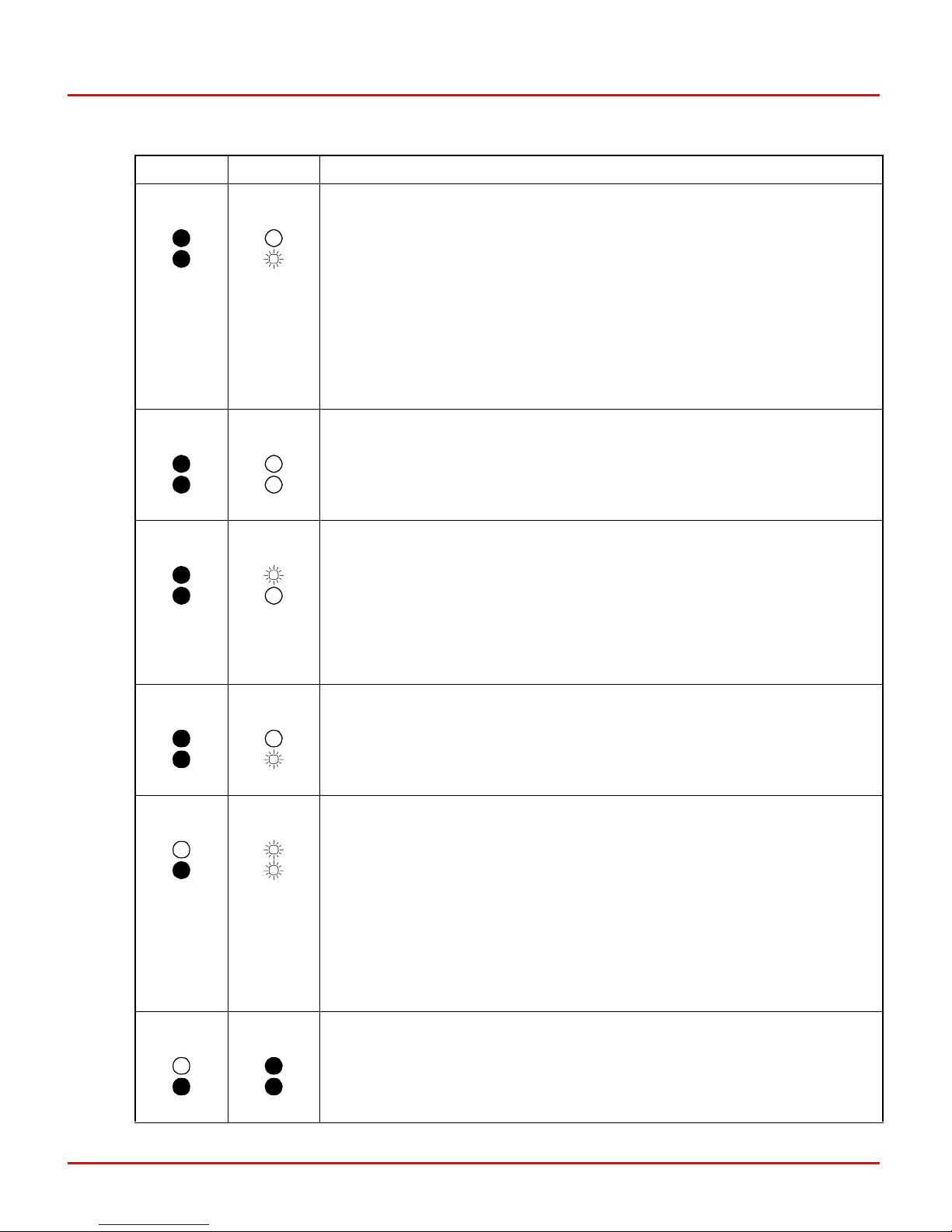
Operation
Table A-2. Backup Cycle
Primary Backup Procedure
n
01xx0x0x
n
01xx0x0x
n
01xx0x0x
10xx1x0x
00xx1x0x
10xx1x0x
n+1
n+1
n+1
(continued )
5. When the checkpoint data for the old configuration is received from the
primary module, the reconfigured backup module can assume the role of
the primary module if a failure is detected in the old configuration (Step 8).
However, the primary module still indicates that no backup is available
when the configuration is different.
Additional configuration changes can be made by entering configure
mode (Step 2). If no changes have been made, a backup module reset
returns the backup to the state of Step 1. If changes have been made, the
backup must be put into configure mode and initialized to get to the state
of Step 1.
6. After the changes have been made, tell the reconfigured backup module to assume the role of the primary module by pressing and releasing
the stop/release button on the backup module 2 times. The first time stops
the module; the second time resets the module. The backup module
comes up in execute mode with the configuration marked as valid.
7. Backup cycle step transitions 5 to 6 to 7 to 8 occur automatically after
the Step 5 backup module reset. The time it takes to complete these transitions depends on BRC configuration. The status indicated in cycles 5, 6
and 7 may not be seen depending on the actual step transition times. The
important status to wait on is indicated by Step 8.
After the checkpoint data is updated, the backup module is ready to take
over the duties of the primary module.
n
01xx0x0x
n+1
01xx0x0xn01xx1x0x
n+1
10xx0x0xn00xx0x0x
n+1
11xx1x0x
8. The backup module requests the primary module to shut down and
assume the role of a hot backup (n+1). The backup module waits to act as
the primary module (n). A hot backup retains the old configuration and
control data and is ready to assume control if an error is detected in the
new configuration.
9. The primary module has removed the bus clock (BUSCLK) and acts as
a hot backup (n+1). The reconfigured backup module is now serving as
the primary module (n).
Before proceeding to the following commands, insure that LED/module
status is as shown in Step 8. To return to Step 4, reset the backup module
(n). This allows correcting a bad configuration.
The primary module (n+1) must be reset at this point for the online configuration cycle to complete. Resetting the primary module (n+1), currently
acting as the hot backup, tells it to get a copy of the new configuration.
10. After the backup module copies the new configuration into the primary
module, the cycle is complete. The backup module is now serving as the
primary module (n) while the primary handles the backup role (n+1). The
LED combination and module status is the opposite of Step 1, indicating
the role reversal.
WBPEEUI230017B1 A - 5
Page 93

Operation
CFG THEN EXT
I/O INTE RFACE
10
PRIMARY
EXT
CONFIGURATION
IS COPIED TO
THE BACKUP
9
PRIMARY
EXT
I/O IN T ERFAC E
1
BACKUP
EXT
RESET
(NO CH A N GE )
IN IT IALIZ E
CFG
RESET (CONFIGURATION NOT COPIED)
I/O IN T ER FAC E
BACKUP
EEROM
BACKUP
CFG
I/O IN T ER FAC E
ERR
CFG
2
3
EXT
I/O IN T ERFAC E
EXT
PRIMARY
CFG
3A
ERR
I/O INTE RFACE
BACKUP
EXT
CHECKPOINT DATA
IS CO MPLE TE
BACKUP
EXT
RESET
(CHANGES MADE)
4
5
8
BACKUP
EXT
Figure A-1. Backup Cycle
Primary Cycle
REQUEST
SHUTDOWN OF
PRIMARY
LEGEND:
EXT = EXECUTE MO DE
CFG = CON FIGURATION MODE
ERR = ERROR M ODE
I/O IN T ER FAC E
BACKUP
= LOSS OF BOTH HNET CH ANNELS
OR EXPANDER BUS CLOCK
7
EXT
CHECKPOINT
DATA IS
COMPLETE
STEP
ROLE
MODE
6
BACKUP
EXT
T017 39A
Refer to Table A-3 for the primary cycle procedure. The step
numbers in this cycle correspond to the states of Figure B-2.
This information is provided for status purposes. Follow the
backup cycle procedures to perform online configuration.
A - 6 WBPEEUI230017B1
Page 94

Table A-3. Primary Cycle
Primary Backup Procedure
Operation
n
01xx0x0x
n+1
01xx0x0xn11xx1x0x
n+1
01xx0x0xn01xx1x0x
n+1
00xx0x0xn00xx1x0x
n+1
10xx0x0xn00xx0x0x
n+1
10xx1x0x
1. The primary module is actively controlling the process. This represents the same juncture as Step 4 of the backup cycle.
2. When the shutdown request is received from the backup module
(Step 7 of the backup cycle), the primary module stops executing and
removes the bus clock (BUSCLK).
3. The primary module is now acting as the hot backup (n+1). All old configuration and block output information remains intact from when it is shut
down in Step 2. If the new configuration is not operating as expected, the
primary module, currently acting as the hot backup (n+1), can take control using the old configuration and block output information (returns to
Step 1).
4. Resetting the primary module (n+1), currently acting as the hot
backup, directs it to get a copy of the new configuration (Step 8 of the
backup cycle).
5. When the new configuration has been copied, the backup module has
completed its cycle and is now serving as the primary module.
n+1
10xx0x0xn00xx0x0x
6. After the checkpoint data is complete, the primary module is now serving as the backup module and is ready to take over the control process
with the updated configuration. The primary cycle is complete. This represents the same juncture as Step 10 of the backup cycle.
WBPEEUI230017B1 A - 7
Page 95

Operation
I/O IN T ERFACE
6
BACKUP
EXT
1
PRIMARY
EXT
IS C O M P LE T E
5
BACKUP
EXT
LEGEND:
EXT = EXECUTE MODE
I/O IN T ERFAC E = L OSS O F BOTH HNET C HAN N E LS
O R EXPAND E R BUS C LO CK
SHU TDOWN
REQUESTED
I/O INTE R FAC E
COPY THE
PRIMARY’S
CONFIGURATION
2
PRIMARY
EXT
4
BACKUP
EXT
SHUTDOWN
COMPLETE
3
HOT
BACKUP
EXT
RESETCHECKPOINT DATA
STEP
ROLE
MODE
T02466A
Figure A-2. Primary Cycle
A - 8 WBPEEUI230017B1
Page 96

NTMP01 Termination Unit
Description
The Harmony bridge controller (BRC) and processor bus
adapter (PBA) combination uses an NTMP01 termination unit
to connect two auxiliary serial I/O ports and IISAC01 Analog
Control Stations. Jumpers on the NTMP01 termination unit
configure the two RS-232-C ports for data terminal equipment
(DTE) or data communication equipment (DCE). One of the
RS-232-C ports can be configured as an RS-485 port. Refer to
the NTMP01 instruction for complete information on
applications.
Figures B-1 through B-4 show the jumper configurations for
jumpers J1 and J2. Figure B-5 shows the jumper configurations for jumpers J3 through J10. Figure B-6 shows the
NTMP01 connector assignments and jumper locations.
Figure B-7 shows how to connect redundant BRC modules and
PBA boards.
Jumpers J11 and J12 are storage posts for extra jumpers.
Jumper J13 is normally set with pins one and two connected.
This connects the cable shielding pin of connector P7 to chassis ground. Jumper J18 configures the terminal serial port for
RS-485 operation when pins two and three are connected and
connector P7 is used instead of connector P5.
Appendix B
WBPEEUI230017B1 B - 1
Page 97

Description
J1 AND J2
TXD-A
RXD-A
RTS-A
CTS-A
1
11
3
4
2
5
6
7
8
9
10
12
Figure B-1. DTE Jumper Configuration (NTMP01)
J1 AND J2
TXD-A
RXD-A
1
3
4
2
RXD
TXD
RTS
CTS
RXD
TXD
DB25-3
DB25-2
DB25-4
DB25-5
DB25-3
DB25-2
5
6
RTS-A
11
CTS-A
7
8
9
10
12
Figure B-2. DCE Jumper Configuration (NTMP01)
RTS
CTS
DB25-4
DB25-5
T01356A
B - 2 WBPEEUI230017B1
Page 98

Description
TXD-A
RXD-A
RTS-A
CTS-A
1
11
J1 AND J2
3
4
5
6
7
8
9
10
2
12
RXD
TXD
RTS
CTS
Figure B-3. Nonhandshake Jumper Configuration (NTMP01)
J1 AND J2
TXD-A
DB25-3
DB25-2
DB25-4
DB25-5
T01357A
RXD
DB25-3
1342
5
RTS -A RTS
CTS-A
7
911 10 12
Figure B-4. Loopback Jumper Configuration (NTMP01)
6
8
TXDRXD-A
CTS
DB25-2
DB25-4
DB25-5
T01358A
WBPEEUI230017B1 B - 3
Page 99

Description
+12 V
J6 AND J8
1
J5 AND J9
1
J7 AND J10
1
J4 AND J3
1
NOTE:
JUMPERS J3, J8, J9 AND J10 RELATE TO THE P6
CONNECTOR. JUMPERS J4, J5, J6 AND J7 RELATE
TO THE P5 CONNECTOR.
Figure B-5. Jumpers J3 through J10 Configuration (NTMP01)
2
2
2
2
DSR
DCD
DTR
PROT-GND
GND
DB25-6
DB25-8
DB25-20
DB25-1
DB25-7
T01359A
B - 4 WBPEEUI230017B1
Page 100
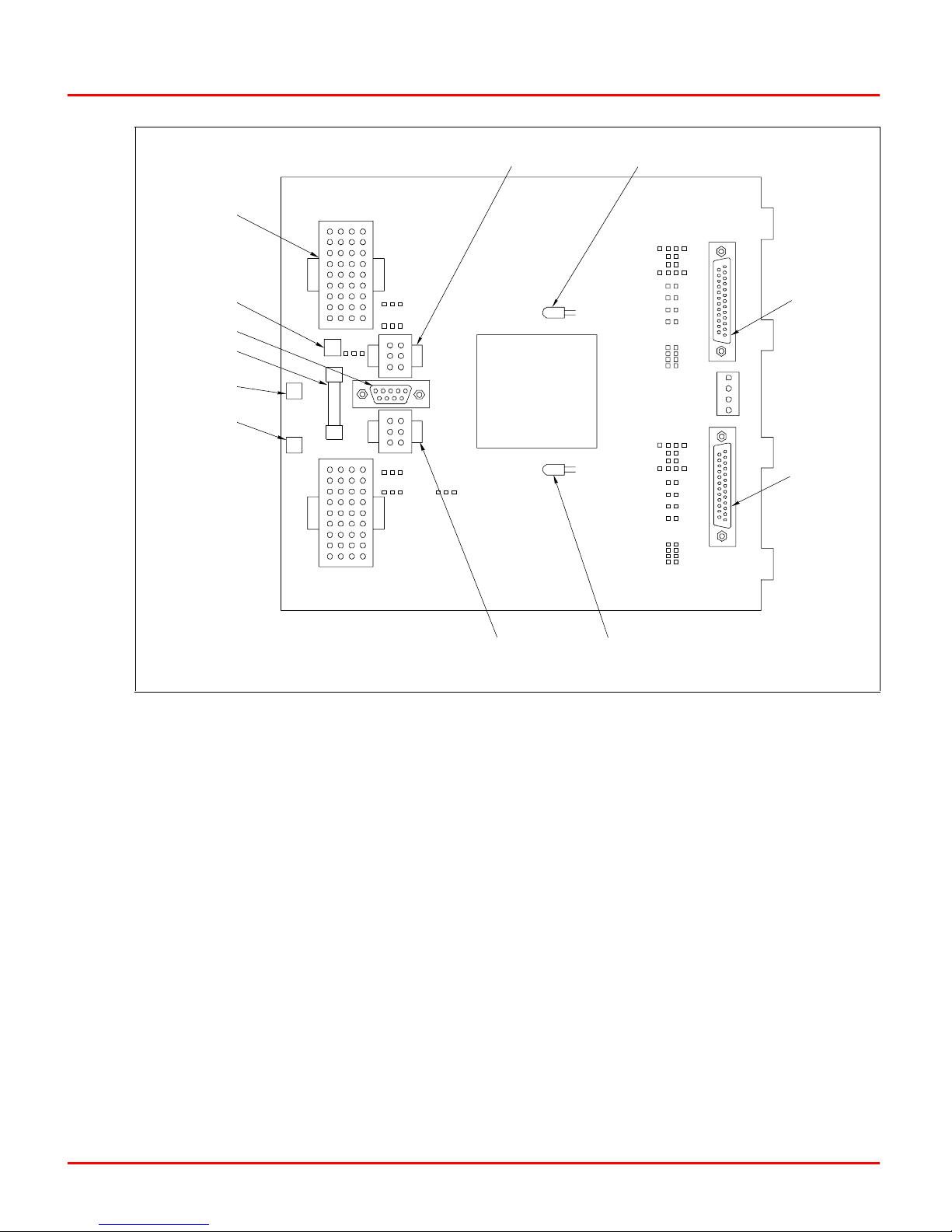
Description
BRC
+24 V
RS-485 PORT
FUSE F1
CHASSIS
GROUND
COM
NTMP01
E2
E1
E3
P2
P1
J16
J17
J14
J15
P4
P3
P7
J18
STATION
COM. B
CR1
CR2
BRC
ACTIVE LED
J2
J4
J5
J6
J7
J12
SPARE
J1
J3
J9
J8
J10
J11
SPARE
P5
TERM INAL
PORT
P8
PRINTER
PORT
P6
Figure B-6. NTMP01 Board Layout
STATION
COM. A
BRC
ACTIVE LED
T01361A
WBPEEUI230017B1 B - 5
 Loading...